1
Mechanical Installation
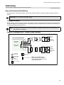
Installing the Adder Modules
FA-300 Series Fire Alarm panels come pre-assembled with all components and boards except for Adder Modules.
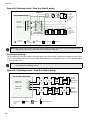
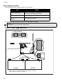
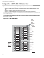
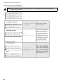
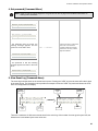
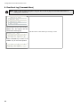
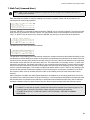
Module installation locations are shown below. Refer to Figure 3 on the next page for Jumper or DIP Switch settings
and see Wiring Tables and Information for wiring specifications.
DET 1
+
DET 2
+
-
DET 3
-
COMMON ALARM
DET 4
IAC1
(ZONE 1)
AC ON
X
CLASS-A converter
board for detection
circuits ICAC-306 (6
circuits )
+
JW3
+
Figure 2: Installation of Adder Modules
COMMON SUPV
DET 6
+
-
SIG 1
IAC6
(ZONE 1)
NAC1
(ZONE 1)
LAMP
TEST
NAC2
(ZONE 2)
BUZZER
SILENCE
NAC3
(ZONE 3)
FIRE DRILL
NAC4
(ZONE 4)
+
SIG 3
+
-
SIG 4
AUX
+
-
4-WIRE SPLY
JW2
TO RM-306 RELAY MODULE
+
TROU BLE
RELAY
JW1
TO PR-300 MO DULE
-
SUPERVISORY
RELAY
-
AUXILIARY
DISCONNECT
SIG 2
SIGNAL
SILENCE
-
JW6
+
JW5
CLASS-A converter
board for indicating
circuits OCAC-302
(2 circuits )
+
IAC5
(ZONE 5)
SYSTEM
RESET
AL ARM RELAY
AUX. RELAY
RS-4 85
+
S
NC
IAC4
(ZONE 4)
CPU FAIL
WALK TEST
POWER SUPPLY
C
NO
NC
C
NO
NC
C
NO
NC
C
NO
JW7
GROUND FAULT
-
IAC3
(ZONE 3)
REMOTE TROUBLE
?
JW4
+
BATTERY TROUBLE
DET 5
IAC2
(ZONE 2)
COMMON TROUBLE
M
Transformer
RTI PORT UNFLTD SPLY
POWER
SIGNAL
TRB TRL COM- COM+
P6
P6
P5
BATTERY
8
SEC TX
AC wiring terminal
P2
P4
Relay Module RM-306
P3
+
BATTERY
P1
Reverse polarity and city
tie module PR-300.
Mounted on hex spacer
with two screws provided
BATTERY