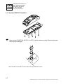
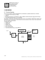
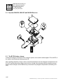
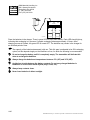
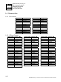
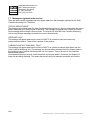
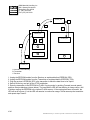
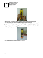
1
English
22.2.2007
RACON SERIES II RADIO CONTROL
SERVICE MANUAL
R&M Materials Handling, Inc.
4501 Gateway Boulevard
Springfield, Ohio 45502
P.: (937) 328-5100
FAX: (937) 325-5319
Read the instructions supplied with the product before installation and commissioning.
Keep the instructions in a safe place for future reference.
Table of content
1 MAJOR UPDATE HISTORY (ONLY IN
ENGLISH)............................................................ 3
2 SAFETY PRECAUTIONS ............................... 4
3 DESCRIPTION................................................ 5
3.1 General ....................................................... 5
3.2 System Specifications................................. 5
4 TRANSMITTER............................................... 7
4.1 Transmitter summary.................................. 7
4.2 Exploded RAD-TS Transmitter ................... 8
4.3 Exploded RAD-TF Transmitter ................... 8
4.4 Exploded RAD-TH Transmitter ................... 9
5 RECEIVER .................................................... 11
5.1 Receiver Summary ................................... 11
5.2 Exploded RAD-RS, RAD-RF and RAD-RH
Receiver............................................................. 12
5.3 The BC70K battery charger ...................... 12
5.4 RADS11 Receiver Connections................ 14
5.5 RADF13 Receiver Connections................ 15
5.6 RADH11 Receiver Connections ............... 16
6 FREQUENCY MANAGEMENT..................... 17
6.1 System description ................................... 17
6.2 Definitions ................................................. 17
6.3 Frequency settings ................................... 17
6.3.1
6.3.2
6.3.3
6.4
6.4.1
6.4.2
7 ACCESS TO THE HOIST CONDITION
MONITORING UNIT.......................................... 21
7.1 General Description of Service Mode ...... 21
7.2 Entering the Service mode....................... 21
7.3 Keys for moving within the Menus. .......... 22
7.4 Switching from Tared Load to Actual Load.
22
7.5 Resetting the Tared Load......................... 22
7.6 Exiting Service mode. .............................. 22
7.7 Messages originated in the receiver. ....... 23
8 EEPROM ...................................................... 24
8.1 Description ............................................... 24
8.2 Replacement EEPROM from Transmitter to
Transmitter ........................................................ 25
8.3 Copying EEPROM from Receiver to
Transmitter ........................................................ 26
9 TROUBLESHOOTING ................................. 29
9.1 Drawings .................................................. 29
9.1.1
9.1.2
9.2
9.3
9.3.1
9.4
Frequency lists.......................................... 20
9.4.1
9.4.2
9.4.3
9.4.4
EU countries ..................................................20
USA and Canada ...........................................20
9.5.1
Entering in frequency programming mode ....17
Frequency programming mode......................18
Exiting the frequency programming mode.....19
9.5
9.6
9.6.1
Transmitter board...........................................29
Receiver board...............................................30
LED indications ........................................ 31
General System Check ............................ 31
Chart S0.........................................................31
System totally downs ............................... 32
Chart S1.........................................................32
Chart T1 .........................................................33
Chart T2 .........................................................34
Chart T2 .........................................................35
Failure of one of the functions.................. 36
Chart S2.........................................................36
Intermittent failures................................... 37
Chart S3.........................................................37
2/37
R&M Materials Handling, Inc. reserves the right to alter or amend the above information without notice.
R&M Materials Handling, Inc.
4501 Gateway Boulevard
Springfield, Ohio 45502
P.: (937) 328-5100
FAX: (937) 325-5319
1 MAJOR UPDATE HISTORY (ONLY IN ENGLISH)
Section
Hole manual
Description, Installation
Description
RADH11 added
BC60K battery charger changed to BC70K
Date
Handled by
22.2.2007 KHHHLE
22.2.2007 KHHHLE
3/37
R&M Materials Handling, Inc. reserves the right to alter or amend the above information without notice.
R&M Materials Handling, Inc.
4501 Gateway Boulevard
Springfield, Ohio 45502
P.: (937) 328-5100
FAX: (937) 325-5319
2 SAFETY PRECAUTIONS
These instructions must be read carefully prior to any intervention in the system.
This Service Manual is intended for authorized personal, instructed in radio remote control
repairing.
Strictly follow to the instructions contained in this manual
Ensure that all site and prevailing safety regulations are fully respected.
When carrying out repairs, only use spare parts supplied by the manufacturer.
Disconnect the receiver cable if soldering/welding work is going to be carried out on the
crane.
Never make any changes to the set, which have not been studied and approved by the
manufacturer.
4/37
R&M Materials Handling, Inc. reserves the right to alter or amend the above information without notice.
R&M Materials Handling, Inc.
4501 Gateway Boulevard
Springfield, Ohio 45502
P.: (937) 328-5100
FAX: (937) 325-5319
3 DESCRIPTION
3.1
General
The RADS11, RADF13 and RADH11 push-button transmitter type, radio remote control systems, are
designed for the remote control of hoists and cranes, and are particularly suitable for applications when
the operator needs to be able to choose the best location from which to carry out an operation.
RADS11 system, colloquially denominated system SINGLE, is made of:
• RAD-TS transmitter
• RAD-RS receiver
• Battery charger BC70K with two NiMH batteries.
RADF13 system, colloquially denominated system FULL, is made of:
• RAD-TF transmitter
• RAD-RF receiver
• Battery charger BC70K with two NiMH batteries.
RADH11 system, colloquially denominated system SINGLE, is made of:
• RAD-TH transmitter
• RAD-RH receiver
• Battery charger BC70K with two NiMH batteries.
3.2
System Specifications
RADS11 / RADF13 / RADH11 Systems
In EU countries
Frequency band
869.7 to 870MHz
Baud rate
7200 bps
Channel separation
12.5 KHz
Channel Occupation
7.2 KHz
Modulation
FM (GMSK)
Response Time
100 ms
Temperature range
-20ºC to +65ºC
The RAD-TS, RAD-TF and RAD-TH transmitters
Transmission power
<5 mW
Protection
IP65
The RAD-RS, RAD-RF and RAD-RH receivers
Power supply
48 Vac, 115 Vac, 230Vac
± 10%, 50/60 Hz
Consumption
30 W
Relays
230 Vac/8 A
Protection
IP55
Communication
Protection against electric shock
The BC70K battery charger
Power supply (± 10%)
The BT06K batteries
Voltage
In North America
902 to 928MHz
25 KHz
-4F to 150F
NEMA 4
48 Vac, 115 Vac
± 10%, 50/60 Hz
NEMA 12
CL20mA (RAD-RF only)
Class II according EN50178 (1997)
230 Vac 50/60Hz
115Vac, 50/60 Hz
4.8 V
5/37
R&M Materials Handling, Inc. reserves the right to alter or amend the above information without notice.
R&M Materials Handling, Inc.
4501 Gateway Boulevard
Springfield, Ohio 45502
P.: (937) 328-5100
FAX: (937) 325-5319
Capacity
Charging temperature
Operating Time
700 mAh, NiMH
5ºC to 35ºC
41F to 95F
12h at 50% RAD-TS and RAD-TH model.
8h at 50% RAD-TF model.
6/37
R&M Materials Handling, Inc. reserves the right to alter or amend the above information without notice.
R&M Materials Handling, Inc.
4501 Gateway Boulevard
Springfield, Ohio 45502
P.: (937) 328-5100
FAX: (937) 325-5319
4 TRANSMITTER
4.1
Transmitter summary
Transmitters RAD-TS and RAD-TH contains the following elements:
• Power ON key-switch, Start Pushbutton, Stop pushbutton and 4 or 6 pieces 2-steps Pushbuttons.
• 4.8V 700 mAh battery.
• Microprocessor driven logic, circuit LE60KM.
• Removable EEPROM memory module EP60K.
• Synthesised radio transmitter T800
• Antenna.
Transmitter RAD-TF also includes:
• Hoist Selector switch and LCD display.
• Expansion unit, circuit LE60KX with LCD and two selector switches.
• Synthesised radio transceiver TR800 instead of transmitter T800.
EEPROM EP60K
Antenna
Radio:
1 Power Key
TR800 RADF13
2 Stop switches
Logic Unit
12 Pushbuttons micro
switches
LE60KM
T800 RADS11 and RADH11
LCD
Expansion:
LE60KX in RADF13
Battery
Two selection microswitches
7/37
R&M Materials Handling, Inc. reserves the right to alter or amend the above information without notice.
R&M Materials Handling, Inc.
4501 Gateway Boulevard
Springfield, Ohio 45502
P.: (937) 328-5100
FAX: (937) 325-5319
4.2
Exploded RAD-TS Transmitter
c_radts_se
Make sure the POWER ON SWITCH is in OFF (0) position when mounting. Otherwise the power
switch could be damaged.
4.3
Exploded RAD-TF Transmitter
Make sure the POWER ON SWITCH is in OFF (0) position when mounting. Otherwise the power
switch could be damaged.
8/37
R&M Materials Handling, Inc. reserves the right to alter or amend the above information without notice.
R&M Materials Handling, Inc.
4501 Gateway Boulevard
Springfield, Ohio 45502
P.: (937) 328-5100
FAX: (937) 325-5319
4.4
Exploded RAD-TH Transmitter
c_radh11_se
Make sure the POWER ON SWITCH is in OFF (0) position when mounting. Otherwise the power
switch could be damaged.
RAD-TS, RAD-TF and RAD-TH bottom side. Extracting EEPROM module.
9/37
R&M Materials Handling, Inc. reserves the right to alter or amend the above information without notice.
R&M Materials Handling, Inc.
4501 Gateway Boulevard
Springfield, Ohio 45502
P.: (937) 328-5100
FAX: (937) 325-5319
Explosion of mechanisms in RAD-TF upper cover
10/37
R&M Materials Handling, Inc. reserves the right to alter or amend the above information without notice.
R&M Materials Handling, Inc.
4501 Gateway Boulevard
Springfield, Ohio 45502
P.: (937) 328-5100
FAX: (937) 325-5319
5 RECEIVER
5.1
Receiver Summary
The receivers RAD-RS, RAD-RF and RAD-RH, are contained in a plastic material box, it includes:
• Synthesised radio transceiver TR800
• Antenna
• Microprocessor driven logic R6012KF, which in addition contains the power supply and the relays.
• Removable EEPROM memory module EP60K.
The supply, is alternating current with connections for 230, 115 and 48 VAC. RAD-RF also contains a bidirectional current loop serial port, which allows the communication with the external Crane Supervision
Unit, not included in this manual.
It includes the relays:
• START relay
• HORN relay
• SAFETY relay
• Two STOP relays
• Nine operating relays
• Two Hoist selection relays (Only RADF13)
EEPROM EP60K
CL20mA
Antenna
Radio
TR800
R6012KF
Logic Unit
Crane
Supervision
Unit
Output
Relays
AC Supply
11/37
R&M Materials Handling, Inc. reserves the right to alter or amend the above information without notice.
R&M Materials Handling, Inc.
4501 Gateway Boulevard
Springfield, Ohio 45502
P.: (937) 328-5100
FAX: (937) 325-5319
5.2
Exploded RAD-RS, RAD-RF and RAD-RH Receiver
5.3
The BC70K battery charger
Connect the charger to the power source using the power source and the cable supplied. The red LED, in
the middle, should light up indicating power ON.
When installing the battery charger, bear in mind that the batteries must be charged at temperatures over
5ºC (41F) and that the power supply must be left on all night. Also remember that the charger must not
be left in direct sunlight, as the batteries may not become fully charged at temperatures exceeding 35ºC
(95F).
12/37
R&M Materials Handling, Inc. reserves the right to alter or amend the above information without notice.
R&M Materials Handling, Inc.
4501 Gateway Boulevard
Springfield, Ohio 45502
P.: (937) 328-5100
FAX: (937) 325-5319
BC70K
c_bc70k1a
Place the batteries in the charger. There is green LED on top of each battery. Each LED should light up,
indicating that recharging is in process. Complete recharging takes approximately 12 hours. After
charging process is finished, the green LED is turned OFF. The batteries may remain in the charger for
an unlimited period of time.
The capacity of the batteries decrease(s) with use. Their life span is estimated to be 500 recharging
cycles, but this depends largely on the conditions of use, for which the following is recommended:
Do not recharge the battery until it is completely empty. The transmitter will indicate this
when to recharge the batteries.
Always charge the batteries at temperatures between 5ºC (41F) and 35ºC (95F).
Avoid short-circuits between the battery contacts. Do not carry charged batteries in
toolboxes or next to other metal objects (keys, coins, etc.).
Always keep contacts clean.
Never leave batteries in direct sunlight.
13/37
R&M Materials Handling, Inc. reserves the right to alter or amend the above information without notice.
R&M Materials Handling, Inc.
4501 Gateway Boulevard
Springfield, Ohio 45502
P.: (937) 328-5100
FAX: (937) 325-5319
5.4
RADS11 Receiver Connections
c_rcel1e
S. Stop
K1. Safety
K2. Start
B. Bridge
H. Hoisting
T. Trolley
14/37
R&M Materials Handling, Inc. reserves the right to alter or amend the above information without notice.
R&M Materials Handling, Inc.
4501 Gateway Boulevard
Springfield, Ohio 45502
P.: (937) 328-5100
FAX: (937) 325-5319
Function
Phase
Protective earth
Neutral
48VAC
115VAC
230VAC
COM Start-horn
Start
Horn
Safety
Bridge forward
Bridge backward
Bridge fast
Hoisting up
Hoisting down
Hoisting fast
Trolley right
Trolley left
Trolley fast
5.5
PCB Relay
K2
K12
K1
K11
K10
K9
K8
K7
K6
K5
K4
K3
PCB Terminal
RL0.1
RL0.2
RL0.3
RL0.4
RL0.5
RL2.3
RL2.4
RL2.7
RL2.9
RL3.2
RL3.3
RL3.4
RL3.6
RL3.7
RL3.8
RL3.10
RL3.11
RL3.12
Wire
1
PE
Pin connector
1
PE
2
2
4
3
12
5
6
7
8
9
10
11
13
14
15
4
3
12
5
6
7
8
9
10
11
13
14
15
1
9
8
16
c_rad_se1
RADF13 Receiver Connections
c_rcel2a
C. Current Loop
S. Stop
K1. Safety
K2. Start
B. Bridge
H. Hoisting
T. Trolley
15/37
R&M Materials Handling, Inc. reserves the right to alter or amend the above information without notice.
R&M Materials Handling, Inc.
4501 Gateway Boulevard
Springfield, Ohio 45502
P.: (937) 328-5100
FAX: (937) 325-5319
Function
Phase
Protective earth
Neutral
48VAC
115VAC
230VAC
Selection-1
Selection-2
COM. Start-horn
Start
Horn
Safety
Bridge forward
Bridge backward
Bridge fast
Hoisting up
Hoisting down
Hoisting fast
Trolley right
Trolley left
Trolley fast
Current loop
Current loop
5.6
PCB Relay
-
PCB Terminal
RL0.1
RL0.2
RL0.3
Wire
1
PE
Pin connector
1
PE
-
RL0.4
2
2
K14
K13
K2
K12
K1
K11
K10
K9
K8
K7
K6
K5
K4
K3
-
RL0.5
RL1.13
RL1.16
RL2.3
RL2.4
RL2.7
RL2.9
RL3.2
RL3.3
RL3.4
RL3.6
RL3.7
RL3.8
RL3.10
RL3.11
RL3.12
RL4.2
RL4.3
16
17
4
3
12
5
6
7
8
9
10
11
13
14
15
18
19
16
17
4
3
12
5
6
7
8
9
10
11
13
14
15
18
19
1
13
12
24
c_rad_se_2
RADH11 Receiver Connections
PE
9
1
2
RADH11
K3
K4
K5
K6
K7
K8
K9
K10
K11
AC
K12
K2
N230V
N115V
N48V
K1
1
DC
3
11
5
4
13
2
6
3
7
4
8
6
9
7
8
1.Stop
2.Control voltage
3.Start horn
4.Up
5.Down
6.Fast speed
7.Right
8.Left
9.Fast speed
16/37
R&M Materials Handling, Inc. reserves the right to alter or amend the above information without notice.
R&M Materials Handling, Inc.
4501 Gateway Boulevard
Springfield, Ohio 45502
P.: (937) 328-5100
FAX: (937) 325-5319
6 FREQUENCY MANAGEMENT
6.1
System description
RADS11, RADF13 and RADH11 remote controls are equipped with microprocessor controlled synthesised
frequency radio modules in both transmitter and receiver. This allows a simple frequency change in the transmitter,
as well as an automatic search by the receiver for the new frequency.
6.2
Definitions
Channel:
Allowed
channels:
Operating
channel:
6.3
Is the reference number of a frequency. See “Frequency lists”.
A list of authorised channels (max 70). This is defined in the factory and cannot be
changed. The Frequency List could be different from one country to another
according to frequency regulations.
Radio channel that is selected
Frequency settings
The system comes from the factory with the channel programmed in the EEPROM module.
When needed, the Operating Channel can be modified to another frequency channel within the allowed
frequency list, which is included in EEPROM module.
6.3.1 Entering in frequency programming mode
The Operating Channel selection can be carried out through commands, which in the
operation mode correspond to orders. Therefore it is of prime importance to follow the
sequence described in order to avoid movements of the machine.
To enter into programming mode follow the sequence:
1. Put a charged battery in the transmitter.
2. Move close to the receiver.
3. Turn on the key-switch.
4. Push down STOP pushbutton (See picture below).
5. Pull up STOP pushbutton (See picture below).
17/37
R&M Materials Handling, Inc. reserves the right to alter or amend the above information without notice.
R&M Materials Handling, Inc.
4501 Gateway Boulevard
Springfield, Ohio 45502
P.: (937) 328-5100
FAX: (937) 325-5319
6. Press Down Pushbutton to the second step.
7. Same time press START
will flash in red.
during 2 seconds (See picture below). During this sequence the LED
8. During next 4 seconds orange pulse in the LED will indicate that Programming mode is entered.
9. Immediately after this, the LED will indicate the Operating Channel selected at this time, though
sequence of green and red pulses, in the following way:
a. Tens, by green pulses
b. Units, by red pulses
10. As an example, the channel 21 will be indicated by 2 pulses in green, followed by 1 pulse in red.
11. After this, the LED will turn orange and the transmitter will be ready for the introduction of new
Operating Channel number (see next paragraph). Otherwise you can leave the programming mode by
pressing Stop button.
6.3.2 Frequency programming mode
1. Once Operating Channel in service is indicated, you can select a new frequency from the list of
Allowed Channels contained in “Frequency lists” paragraph, by pressing the DOWN button (tens), and
the UP button (units). The LED through an orange flash indicates each pulse. (See picture below).
18/37
R&M Materials Handling, Inc. reserves the right to alter or amend the above information without notice.
R&M Materials Handling, Inc.
4501 Gateway Boulevard
Springfield, Ohio 45502
P.: (937) 328-5100
FAX: (937) 325-5319
2. The LED, for checking, as explained in the previous point, indicates a short while after the last pulse,
the new Operating Channel. Some orange pulses by the LED indicate that the new Operating Channel is
sent to the receiver. When this transmission has finished, the LED remains in orange.
3. If the programming of the new Operating Channel has not been correct, try the process again.
4. If the programming of the new Operating Channel has been correct, press STOP. Restarting again, it
will work on the new Operating Channel.
5. If an attempt is made to program a channel outside the Allowed Channel list, the LED will show the
error by lighting up in red.
Once the new channel has been selected, the new frequency will be transmitted to the receiver using
frames with no orders in the old frequency. If the channel change has been performed when the receiver
is switched off, or the receiver has not been able to hear the transmitter, the receiver will SCAN the new
frequency selected, and once scanned it will store this new channel in the EEPROM memory.
The receiver will modify its Operating Channel if it receives frames that contain the new frequency
channel.
In Full systems the LCD Display will show the selected channel (picture below).
6.3.3 Exiting the frequency programming mode
You can exit the programming mode by pressing the STOP button. The new channel will be then stored
in EEPROM.
19/37
R&M Materials Handling, Inc. reserves the right to alter or amend the above information without notice.
R&M Materials Handling, Inc.
4501 Gateway Boulevard
Springfield, Ohio 45502
P.: (937) 328-5100
FAX: (937) 325-5319
6.4
Frequency lists
6.4.1 EU countries
Channel number
1
2
3
4
5
6
7
8
9
10
11
12
Frequency, MHz
869,70625
869,71875
869,73125
869,74375
869,75625
869,76875
869,78125
869,79375
869,80625
869,81875
869,83125
869,84375
Channel number
13
14
15
16
17
18
19
20
21
22
23
24
Frequency, MHz
869,85625
869,86875
869,88125
869,89375
869,90625
869,91875
869,93125
869,94375
869,95625
869,96875
869,98125
869,99375
6.4.2 USA and Canada
Channel number
1
2
3
4
5
6
7
8
9
10
11
12
13
14
15
16
17
18
19
20
21
22
23
24
Frequency, MHz
914,15000
914,17500
914,20000
914,22500
914,25000
914,27500
914,30000
914,32500
914,35000
914,37500
914,40000
914,42500
914,45000
914,47500
914,50000
914,52500
914,55000
914,57500
914,60000
914,62500
914,65000
914,67500
914,70000
914,72500
Channel number
25
26
27
28
29
30
31
32
33
34
35
36
37
38
39
40
41
42
43
44
45
46
47
Frequency, MHz
914,75000
914,77500
914,80000
914,82500
914,85000
914,87500
914,90000
914,92500
914,95000
914,97500
915,00000
915,02500
915,05000
915,07500
915,10000
915,12500
915,15000
915,17500
915,20000
915,22500
915,25000
915,27500
915,30000
Channel number
48
49
50
51
52
53
54
55
56
57
58
59
60
61
62
63
64
65
66
67
68
69
70
Frequency, MHz
915,32500
915,35000
915,37500
915,40000
915,42500
915,45000
915,47500
915,50000
915,52500
915,55000
915,57500
915,60000
915,62500
915,65000
915,67500
915,70000
915,72500
915,75000
915,77500
915,80000
915,82500
915,85000
915,87500
20/37
R&M Materials Handling, Inc. reserves the right to alter or amend the above information without notice.
R&M Materials Handling, Inc.
4501 Gateway Boulevard
Springfield, Ohio 45502
P.: (937) 328-5100
FAX: (937) 325-5319
7 ACCESS TO THE HOIST CONDITION MONITORING UNIT
7.1
General Description of Service Mode
For RADF13 systems, there is a special “Service Mode” of operation for maintenance and set up of the
Hoist Condition Monitoring Unit via radio.
This unit is connected to the receiver RAD-RF by a serial data communication CL20mA.
When in Service mode, the transmitter RAD-TF is able to act as a data console for the Hoist Condition
Monitoring Unit, sending commands and receiving information, using the radio link and the appropriate
software in the transmitter RAD-TF and in the receiver RAD-RF.
During the Service Mode of operation, due to the amount of data being sent in the reverse link, the
amount of frames per second in reverse mode is increased such that the feedback in the display is fast
enough. The movements of the crane in this mode of operation are inhibited, this is, there are no
movement orders being sent by the transmitter or acknowledged by the receiver. The Stop relays are
activated.
It could be too slow to enter in service mode by the receiver if the transmitter and the receiver are
in different channels. Whenever possible, avoid the scanning of radio channels.
7.2
Entering the Service mode.
To access the Hoist Condition Monitoring Unit mode follow the sequence:
1.
2.
3.
4.
Install a charged battery in the transmitter.
Move close to the receiver.
Turn on the key-switch.
Push down STOP pushbutton (If it was in UP
position.)
5. Pull up STOP pushbutton.
6. Press Pushbutton UP in second speed, and then,
START. The system enters in Service Mode.
c_lcdse1a
While the system is in service mode the “envelope” icon in the display will be switched ON.
21/37
R&M Materials Handling, Inc. reserves the right to alter or amend the above information without notice.
R&M Materials Handling, Inc.
4501 Gateway Boulevard
Springfield, Ohio 45502
P.: (937) 328-5100
FAX: (937) 325-5319
7.3
Keys for moving within the Menus.
The keys for moving within the menu are the following:
c_pbkb1a
1. Button that simulates the Down Key (Down button)
2. Button that simulates the Up Key (Up button)
3. Button that simulates the Esc Key (Left button)
4. Button that simulates the Enter Key (Right button)
7.4
Switching from Tared Load to Actual Load.
c_lcdtr1a
The actual load is shown in the display unit as the Tared Load, but an “A” is shown below the “t” in the
bottom right hand side of the display unit. In order to switch from Tared Load to actual load, this is
performed by pressing UP and/or DOWN. Pressing ENTER, the password is requested.
7.5
Resetting the Tared Load.
Pressing the ESC button for several seconds performs the reset of the Tared Load.
7.6
Exiting Service mode.
There are two ways of exiting this mode.
Pressing the STOP button
(The transmitter will be switched OFF and the receiver will switch to standby mode). If the system is
switched ON again and the system was switched OFF in a menu within the service mode, when receiving
the new frames in normal operation, first of all the following message may appear: “EXITING SERVICE
MODE”. The receiver will send as many Escape messages as needed to return to the load message.
Pressing the START button for 3 seconds
The transmitter will switch from Service Mode to Standard mode of operation while the receiver will go to
Standard mode passing through the Standby status. The STOP relays are deactivated and activated
again. If you exit service mode within a menu in the Hoist Condition Monitoring Unit, the system will exit
to the Load status. This may take several seconds where the message “EXITING SERVICE MODE” will
be ON.
22/37
R&M Materials Handling, Inc. reserves the right to alter or amend the above information without notice.
R&M Materials Handling, Inc.
4501 Gateway Boulevard
Springfield, Ohio 45502
P.: (937) 328-5100
FAX: (937) 325-5319
7.7
Messages originated in the receiver.
There are three possible messages that may appear apart from the messages originated by the Hoist
Condition Monitoring Unit. These are:
“EXITING SERVICE MODE”
This message is originated when the Hoist Condition Monitoring Unit is in Service mode within the menus
and the transmitter is in Normal mode of operation. This message will appear prior to show the Load or
Fault messages while exiting the Service mode. The receiver will send the Hoist Condition Monitoring
Unit as many Escape messages as needed to return to Normal mode.
“RECEIVER FAULT”
This message will appear whenever the receiver RADF13 is not able to open the current loop
communications channel. There will be a problem in the receiver.
“CURRENT LOOP NOT AVAILABLE / FAULT”
This message will appear whenever the receiver RADF13 is not able to read any data frame from the
Hoist Condition Monitoring Unit. This message can be seen when switching the unit to display mode or
by unplugging Hoist Condition Monitoring Unit from the receiver. There is an error in the connection
between both systems.
If the transmitter does not receive a valid frame from the receiver within 2.5 seconds, the display will
erase the data being displayed. This means that there is faulty link between transmitter and receiver.
23/37
R&M Materials Handling, Inc. reserves the right to alter or amend the above information without notice.
R&M Materials Handling, Inc.
4501 Gateway Boulevard
Springfield, Ohio 45502
P.: (937) 328-5100
FAX: (937) 325-5319
8 EEPROM
8.1
Description
The information in the EEPROM is:
• ID Code
• Allowed Frequency List and Scanning parameters
• Output configuration
• Out of power off time
• Masks
The radio remote control units RADS11, RADF13 and RADH11 have identical EEPROM’s, in the
transmitter and in the receiver, and in both they are removable
In the transmitter, the EEPROM removing is done from outside of the transmitter, as follows:
1. Remove, from the back of the transmitter the two EEPROM module screws
2. Lift up the EEPROM module using to small screwdrivers
24/37
R&M Materials Handling, Inc. reserves the right to alter or amend the above information without notice.
R&M Materials Handling, Inc.
4501 Gateway Boulevard
Springfield, Ohio 45502
P.: (937) 328-5100
FAX: (937) 325-5319
In the receiver, the process is:
1. Remove the 4 screws from the receiver’s cover
2. Take off the receiver’s cover.
3. Lift up the EEPROM module
8.2
Replacement EEPROM from Transmitter to Transmitter
The replacement of the EEPROM from a existing OLD transmitter which is controlling a crane to another
NEW transmitter, is done as follows:
1. Take the two transmitters and switch them off from the key-switch and the STOP pushbutton
25/37
R&M Materials Handling, Inc. reserves the right to alter or amend the above information without notice.
R&M Materials Handling, Inc.
4501 Gateway Boulevard
Springfield, Ohio 45502
P.: (937) 328-5100
FAX: (937) 325-5319
EEPROM_old
2
3
EEPROM_old
EEPROM_new
OLD TRANSMITTER
3
2
NEW TRANSMITTER
EEPROM_new
2. Remove the screws and lift up the OLD’s EEPROM module as seen before.
3. Plug it in to the NEW transmitter.
4. Close the EEPROM module cover with the two screws.
5. Switch ON the key and pull up the STOP pushbutton.
6. Press START
8.3
.
Copying EEPROM from Receiver to Transmitter
The copying of the receiver’s EEPROM into the transmitter’s EEPROM involve two general processes:
A. The first step consist of copying the receiver’s EEPROM data to the transmitter internal FLASH
memory.
B. The second step consists of copying data from the internal FLASH memory to a new EEPROM
module.
To copy an EEPROM module from one receiver to one transmitter, follow the next steps:
26/37
R&M Materials Handling, Inc. reserves the right to alter or amend the above information without notice.
R&M Materials Handling, Inc.
4501 Gateway Boulevard
Springfield, Ohio 45502
P.: (937) 328-5100
FAX: (937) 325-5319
EEPROM_REC
1
3
6
9
EEPROM_TRA
EEPROM_REC
5
7
8
A
B
2
C
EEPROM_TRA
A. Internal FLASH Memory
B. Transmitter
C. Receiver
1. Unplug the EEPROM module from the Receiver as explained before (EEPROM_REC).
2. Unplug the EEPROM module from the Transmitter as explained before (EEPROM_TRA).
3. Plug the receiver’s EEPROM_REC in the transmitter in which the data have to be copied.
4. Switch ON the key and pull up the STOP pushbutton.
5. Enter the transmitter in the EEPROM to FLASH Copying mode, by pushing Forward (second speed)
and then Start pushbuttons (picture below). The transmitter’s LED will start blinking in orange colour, until
it finishes copying the EEPROM to the internal FLASH memory. If the copying has been successful, the
LED will turns to green. If not the LED will remains in continuous orange. In that case stop the transmitter
and repeat steps 4 and 5.
27/37
R&M Materials Handling, Inc. reserves the right to alter or amend the above information without notice.
R&M Materials Handling, Inc.
4501 Gateway Boulevard
Springfield, Ohio 45502
P.: (937) 328-5100
FAX: (937) 325-5319
6. Maintaining the Transmitter ON, unplug the receiver’s EEPROM_REC from the Transmitter.
7. Plug the transmitter’s EEPROM_TRA module and close the cover with two bolts.
8. Enter the transmitter in the FLASH to EEPROM Copying mode by Pushing Forward button (second
speed), until it starts blinking in orange colour (picture below). If the copying has been successful, the
LED will turns to green colour and the transmitter will switch OFF automatically. Push STOP to exit the
copying mode. In case of an error, the LED will blink in red colour and the transmitter will switch OFF
automatically. If this happen, push STOP and proceed repeating procedure 4.
9. Plug the receiver’s EEPROM_REC module in the receiver.
28/37
R&M Materials Handling, Inc. reserves the right to alter or amend the above information without notice.
R&M Materials Handling, Inc.
4501 Gateway Boulevard
Springfield, Ohio 45502
P.: (937) 328-5100
FAX: (937) 325-5319
9 TROUBLESHOOTING
9.1
Drawings
9.1.1 Transmitter board
1
2
3
4
1. Start switch
2. Up
3. Key switch
4. Stop switches
29/37
R&M Materials Handling, Inc. reserves the right to alter or amend the above information without notice.
R&M Materials Handling, Inc.
4501 Gateway Boulevard
Springfield, Ohio 45502
P.: (937) 328-5100
FAX: (937) 325-5319
9.1.2 Receiver board
1
2
1
3
4
5
6
7
K16
K14
K13
K2
K15
K12
K1
K11
K10
K9
K5
K4
K3
K8
K7
K6
8
K14
+ / AC
N230 / AC
PE
N115 / AC
K13
STOP
K2
K12
K1
K11 K10 K9
K8
K7
K6
K5
K4
K3
- / DC
N48 / AC
1. Up
2. Radio
3. Signal
4. Power
5. Hard
6. ID
7. Data
8. Fuse
30/37
R&M Materials Handling, Inc. reserves the right to alter or amend the above information without notice.
R&M Materials Handling, Inc.
4501 Gateway Boulevard
Springfield, Ohio 45502
P.: (937) 328-5100
FAX: (937) 325-5319
9.2
LED indications
Once the receiver has been powered up, it enters into the SCANNING mode while the own transmitter is
off.
The following receiver green LEDs should now light up:
SIGNAL:
POWER:
HARDOK:
ID:
DATA:
OFF if all radio channels in the band are free.Flashing ON if the receiver is finding channels with RF signals.
ON, indicating that the power supply is correct.
ON, indicating that the board is OK.
OFF
OFF if none of the radio channels contains signals belonging to a RADF13, RADS11 or RADH11 radio remote control system in
the area. Flashing ON if some exists.
On receiving a signal from the transmitter, the receiver will enter into the WORKING mode.
The following receiver LEDs should now light up:
SIGNAL:
POWER:
HARDOK:
ID:
DATA:
9.3
Flashing ON, indicating that it is receiving an RF signal at the working frequency.
ON, indicating that the power supply is correct.
ON, indicating that the board is OK.
Flashing ON each time a good frame is received with ID correct. This means that the receiver has recognised the
transmitter’s identification code
Flashing ON each time a good frame is received not necessary containing the right ID.
General System Check
9.3.1 Chart S0
System check
System Check Init
The system starts?
No
Chart S1
Yes
Chart S2
Yes
Chart S3
Yes
One of the commands doesn’t work?
No
Sometimes, main contactor falls down?
End
31/37
R&M Materials Handling, Inc. reserves the right to alter or amend the above information without notice.
R&M Materials Handling, Inc.
4501 Gateway Boulevard
Springfield, Ohio 45502
P.: (937) 328-5100
FAX: (937) 325-5319
9.4
System totally downs
9.4.1 Chart S1
System doesn’t start
Chart S1
Put a charged battery on the transmitter, turn key ON,
push and pull STOP button.
Does LED give a yellow-green pulse?
No
Go to Chart T1
No
Go to Chart T2
No
Go to Chart R1
No
Replace fuse
End
No
Verify connection cable from
receiver to the crane
End
Yes
Press Start pushbutton.
Does the LED light up green?
Yes
Check LEDs in the receiver.
And all them OFF?
Yes
Check the fuse
Is it OK?
Yes
Check the Power Supply on RLO:
230 Vac between P/AC and N230/AC
115 Vac between P/AC and N115/AC
48 Vac between P/AC and N48/AC
Is it OK?
Yes
Replace Receiver Board
End
32/37
R&M Materials Handling, Inc. reserves the right to alter or amend the above information without notice.
R&M Materials Handling, Inc.
4501 Gateway Boulevard
Springfield, Ohio 45502
P.: (937) 328-5100
FAX: (937) 325-5319
9.4.2 Chart T1
When trying to start the transmitter, LED doesn’t give the Stop-checking signal.
From Chart S1
Open the transmitter,
activate key switch, and
without releasing it, push
and release STOP
switches simultaneously.
Replace the key lock
and close the
transmitter. T ray as
above.
Does LED give a yellowgreen pulse?
Yes
Go to Chart S1
Yes
No
Does LED give a yellowgreen pulse?
Open the transmitter and
replace Stop button.
No
Check input voltage on
pins + and - on
transmitter board.
Is it > 4.8V?
Yes
Replace the
transmitter board.
No
End
Clean battery contacts
and connection to the
board.
End
33/37
R&M Materials Handling, Inc. reserves the right to alter or amend the above information without notice.
R&M Materials Handling, Inc.
4501 Gateway Boulevard
Springfield, Ohio 45502
P.: (937) 328-5100
FAX: (937) 325-5319
9.4.3 Chart T2
Transmitter doesn’t start
From Chart S1
Press Start pushbutton
Does the LED keep OFF?
Yes
No
End
No
Start Function is inoperative. Open the transmitter,
activate key switch, and without releasing it, push and
release STOP switches simultaneously and push
Start switch.
Does the LED flash twice
red?
Yes
Does the LED keep
OFF?
No
Replace START
pushbutton
Yes
An order is activated. Open the transmitter,
activate key switch, and without releasing
it, push and release STOP switches
simultaneously and push Start switch
Replace the
transmitter board
End
End
There is a pushbutton
damaged; check them
and replace the broken
one.
End
No
Does the LED flash twice
red?
Yes
A command switch is
damaged. Replace the
transmitter board.
End
34/37
R&M Materials Handling, Inc. reserves the right to alter or amend the above information without notice.
R&M Materials Handling, Inc.
4501 Gateway Boulevard
Springfield, Ohio 45502
P.: (937) 328-5100
FAX: (937) 325-5319
9.4.4 Chart T2
Receiver doesn’t start, even having good power supply
From Chart S1
The transmitter is OFF
and receiver’s LED
POWER is ON
Is LED HARDOK ON?
No
Replace receiver board
End
Yes
Replace receiver board
End
Yes
EEPROM error. Copy EEPROM
form transmitter
End
Yes
HARDOK flashes slowly?
No
HARDOK flashes fast?
No
ID is OFF and DATA is
flashing?
Yes
The receiver can recognise that there are other systems
RADS11, RADF13 or RADH11 operating in the area
No
Start transmitter
SIGNAL flashing and ID
and DATA OFF?
Yes
Channel selected is fully busy.
Change the frequency
Yes
The receiver receives the signal from the
transmitter, but it cannot recognise ID code.
The channel is too busy. Check that there
are no more than 3 RADS11, 2 RADF13 or 3
RADH11 systems operating on the same
channel.
Change the frequency
No
SIGNAL and DATA
flashing quickly and ID
flashing very slowly?
No
SIGNAL, DATA and ID
flashing. System OK.
This situation persists in every channel
End
Yes
The receiver does not receive
signal from the transmitter
No
System OK
Replace radio transmitter
End
End
35/37
R&M Materials Handling, Inc. reserves the right to alter or amend the above information without notice.
R&M Materials Handling, Inc.
4501 Gateway Boulevard
Springfield, Ohio 45502
P.: (937) 328-5100
FAX: (937) 325-5319
9.5
Failure of one of the functions
9.5.1 Chart S2
System works except one of the commands.
Chart S2
Open the receiver
When pushing the failing command, the
corresponding relay activates?
Yes
System is working properly
Yes
Replace the pushbutton
Check output terminals and
connection from receiver to the
crane.
No
Open the transmitter and start it. Push the
switch of the failing command.
Does the relay activate?
No
Replace the transmitter logic board.
End
36/37
R&M Materials Handling, Inc. reserves the right to alter or amend the above information without notice.
R&M Materials Handling, Inc.
4501 Gateway Boulevard
Springfield, Ohio 45502
P.: (937) 328-5100
FAX: (937) 325-5319
9.6
Intermittent failures
9.6.1 Chart S3
Sometimes the main contactor falls down.
Chart S3
The transmitter led flashes?
Yes
Replace the battery
Yes
This may be due to drops in power
supply to the receiver when
performing the command
Check and correct it.
Yes
Some messages are being lost.
Check the channel and verify that
there are no more than 3 RADS11,
2 RADF13 or 3 RADH11 systems
operating in the area.
No
Drops of the system only occur
when carrying out certain
commands, usually lifting
No
Being the transmitter ON,
sometimes the ID led goes out
No
End
37/37
R&M Materials Handling, Inc. reserves the right to alter or amend the above information without notice.