1
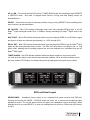
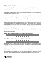
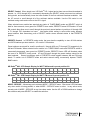
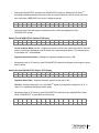
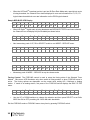
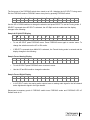
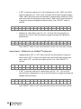
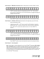
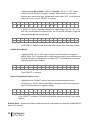
Multi-Tuner Monitor M3 User Manual Welcome" Thanks for purchasing the DaySequerra M3 HD RadioTM Multi-Tuner. We design and build all of our DaySequerra products to be completely reliable and easy to use, so you can concentrate on producing great sounding broadcasts, not struggling with complicated equipment or difficult to use product manuals. While the M3 has been designed to be straightforward to use, we do suggest that you spend a few minutes familiarizing yourself with the features and operational functions that are contained in this manual. DaySequerra has been building broadcast quality products since 1989. The technology developed for the M3, and all of our products, has evolved through a process of user feedback, extensive listening, field-testing and careful refinement. In the event that you encounter any technical or operational difficulties with this or any DaySequerra product, please feel free to contact us at 856-719-9900. Our office hours are from 9 to 5 ET, Monday through Friday. Or you can email your questions to: [email protected]. Also, please remember to visit our website www.daysequerra.com for warranty registration and the latest DaySequerra product information. We have worked hard to ensure that your DaySequerra M3 will reliably serve as a useful link between your source material and your broadcasts. We sincerely hope our products help you achieve a new level of excellence in your work! " " " David"V."Day" and#the"DaySequerra"Team Day Sequerra | 154 Cooper Rd. #902 | W. Berlin, NJ 08091 | Voice 856-719-9900 | [email protected] | www.daysequerra.com 2" M3#User#Manual# Table"of"Contents" Important Safety Information 4 Service Information 4 Introduction 4 M3 Key Features 5 M3 Technical Specifications 5 Unpacking and Installing 6 Front Panel Controls and Indicators 6 Rear Panel Controls and Connectors 9 M3 Operating Description 10 Sample VFD Displays 12 Performance Loss Monitor 18 User Settings 23 One Year Warranty 24 " " " All rights reserved DaySequerra Corp, Copyright 2011. All logos and trademark used herein are the property of their respective owners. Specifications subject to change. M3.0 Revision B. M3#User#Manual# 3" Important"Safety"Information" • • • • • • • • • • Indoor use only. Not for use in wet or damp environments. Maximum Relative Humidity: <80% Class I Equipment (grounded type) Electrical rating: 100-120/220-240V~50-60Hz 18W Fuse Rating: 2A 250V 20MM AC Mains supply voltage fluctuations are not to exceed +10% of the nominal voltage Operations temperature range -40°C to 70°C Maximum altitude: 3000m (9843ft) Equipment suitable for continuous operation Weight: 8.2kg (18lbs) equipment only; 10.9kg (24lbs) shipping Important Note: Please connect your M3 to an uninterruptible power supply (UPS) to provide other protection against power surges and brownouts. Service"Information The DaySequerra M3 contains no user serviceable components inside the unit. Please contact DaySequerra for repair and upgrade information. In the event that your unit needs to be returned to the factory, contact us for a return authorization number. The tuner ID and firmware version is momentarily displayed at tuner start-up for your convenience. Please visit www.daysequerra.com and register your new M3 so we can keep you informed of the latest hardware and software updates. Introduction The DaySequerra M3 HD RadioTM Multi-Tuner is the first broadcast quality monitor available with three AM/FM tuners each complete with multicast capability. The M3 has been designed as the benchmark in sensitivity (< 15.0dBf in FM) and reliability, and at the same time delivers the highest quality, accurate monitoring of existing analog and HD RadioTM AM and FM broadcast signals (THD+N <.005% with stereo separation >90dB for HD RadioTM FM signals). Each of the three independent tuners in the DaySequerra M3 features an ultra low noise RF front-end with built-in preselector and double-balanced mixer, low-jitter DAC and Class-A biased audio outputs provide the highest fidelity reception and demodulation of HD RadioTM programs, including display of program applicable data (PAD) for MPS and multicast signals, including Apple “Buy Button” UFID. Its robust, modular architecture ensures that the M3 will never become obsolete. The rugged M3 chassis houses dedicated hardware RF, audio and power supply modules that, along with firmware updates via flash programmable memory, completely anticipates the growth of new HD RadioTM services and programming. This design approach along with our product update program ensures that a broadcaster’s investment in a DaySequerra product will continue to pay off well into the future. Please read this manual thoroughly before operating your M3. 4" M3#User#Manual# M3"Key"Features THREE SEPARATE AM, FM AND HD RADIO™ TUNERS - dedicated vacuum florescent displays SEPARATE AM AND FM ANTENNA INPUTS – Industry standard 75-ohm “F” connectors DEDICATED HD LOCKED, MULTICAST AVAILABLE, DELAY SET AND TUNER ALARM STEREO ANALOG OUTPUTS – Balanced (+4dBm) for 100% analog modulation AES3 DIGITAL AUDIO OUTPUTS – full-time for all broadcast audio; 110-ohm transformer isolated IEC320 POWER INLET – 120/240VAC via internal solder jumpers; integrated fuse holder SYNTHESIZED, PUSHBUTTON TUNING – AM and FM bands including multicast channels PRESETS – 40 preset stations per tuner HD LOCKED – HD RadioTM audio present, indicates digital carrier SN > 58dB/Hz DELAY BIT – Indicates active analog diversity delay for HD RadioTM broadcasts HEADPHONE OUTPUT – high output, Class A with system processor controlled gain DATA DISPLAY – RDS/RBDS, SIS and PSD data including Apple “Buy Button” UFID data ALARM OUTPUTS – Six rear panel mounted assignable alarm relay contact closures for each tuner POWER LOSS - unit returns to its previous state after momentary power loss M3"Technical"Specifications RF TUNING RANGE AM – 520kHz to 1720kHz in 10kHz increments FM – 87.9MHz to 108.1MHz in 200kHz increments! RF USEABLE SENSITIVITY AM – 30dBf for –20dB SNR @ 30% modulation FM – 15dBf for –30dB SNR @ 100% modulation IF REJECTION AM – greater than 100dB for –20dB SNR FM – greater than 100dB for –30dB SNR ! AF BANDWIDTH AM – + 1dB 40Hz to 15kHz FM – + 1dB 20Hz to 20kHz ! AF THD+N < 0.005% (digital audio) ! > 90dB (digital audio) STEREO CHANNEL SEPARATION ! HD RadioTM HYBRID ACQUISITION HD RadioTM BLEND LEVEL ACCURACY ! HD RadioTM PAD DATA DISPLAY < 4.5 seconds < 0.5dB! Station long and short name, program type, song title, artist, album, genre and comment fields limited to a total of 1018 bytes per message per iBiquity specifications; Apple “Buy Button” UFID M3#User#Manual# 5" Unpacking"and"Installing"the"M3 Immediately upon receiving your M3, please make a careful inspection for any shipping damage. If damage is found or suspected, please notify the carrier at once and then contact your dealer.! ! The DaySequerra M3 is shipped in one carton, which contains: the M3 unit, an AC power cable and this User Manual. We strongly encourage you to save the shipping carton and shipping materials supplied with your M3. They are specially designed to properly protect your M3, and in the event that you need to return it for service, only these OEM shipping materials can ensure its safe return to our factory. We provide a limited 1-year warranty on all of our products, but if you don’t register your unit, it’s hard for us to help you if and when help becomes necessary. So please take a few minutes to complete the warranty registration form on our web site, www.daysequerra.com. Thank you! Rack Mount Installation. The M3 chassis has four rack mounting holes in its chassis and has been designed to fit in a 19” standard 2RU space. Plastic ‘finishing’ washers are recommended to protect the painted finish around the mounting holes. Power Connection. The AC power cable supplied with M3 must be connected from the M3’s IEC320 power entry module to an AC mains outlet with a functional earth ground connection. The M3 has been set at the factory to operate at 120VAC unless otherwise specified on the shipping carton. Please connect your M3 to an uninterruptible power supply (UPS) to protect against power surges and brownouts. Audio Output Connections. Balanced analog audio outputs are on male XLR connectors on the M3 rear panel with pin 1 GND, pin 2 HIGH (non-inverting) and pin 3 LOW (inverting). The M3 digital audio output is transformer isolated in AES consumer format on a male XLR connector on the rear panel with pin 1 XFMR, pin 2 XFMR and pin 3 GND. Front"Panel"Controls"and"Indicators The M3 front panel consists of three independent HD RadioTM tuner areas, with each area containing the following ‘dedicated’ controls and displays: VFD, 4 indicator LED’s and 3 control pushbuttons. The front panel also contains two ‘shared’ switch panels, each consisting of 5 indicator LED’s and 5 control pushbuttons for directing commands to one of the M3’s three individual tuners based on the Tuner 1, 2, 3 switch selection. The functions of ‘dedicated’ and ‘shared’ controls and displays are described below. Dedicated Controls and Displays The following controls and displays are ‘dedicated’ to their respective tuner as defined on the M3 front panel. Vacuum florescent display (VFD) – Multi-function display that indicates current tuner band, frequency, mode, HD RadioTM SIS and PAD data, and RDS/RBDS data from analog FM broadcasts. Also used to display Mode Service, Forcing and Data Display menus. 6" M3#User#Manual# UP and DN – For manual AM and FM tuning in TUNER BAND mode and scrolling through PRESETS in PRESETS mode. Also used to navigate Mode Service, Forcing and Data Display menus, as described below. SELECT – Multi-function switch for selecting multicast tuning, storing PRESETS and controlling other tuner functions, as described herein. HD LOCKED – Blue LED indicator illuminates when tuner has acquired OFDM portion of an HD RadioTM signal and digital carrier SN is > 58dB/Hz, thereby permitting HD RadioTM digital audio to be valid. MULTICAST – Blue LED indicator illuminates when tuner has acquired OFDM of an HD RadioTM signal and there is at least one multicast signal present, i.e., HD-2 through HD-8. DELAY SET – Blue LED indicator illuminates when tuner has acquired OFDM of an HD RadioTM MPS signal and the analog diversity delay is active. The LED is off when there is no delay bit set, i.e. “ball game mode” meaning that the analog program has not been delayed to be coincident with the HD RadioTM MPS signal. TUNER ALARM – Red LED indicator identifies a detected alarm condition in any tuner module. It is solid when any alarm on the selected tuner has been enabled. When an alarm condition occurs, the tuner module’s LED flashes, the beeper beeps and the appropriate rear panel contact closes. M3 Front Panel Layout "" HEADPHONES. Headphone stereo output is via a recessed front panel mounted mini-TRS jack. Pressing and holding the MODE – SERVICE button will allow you to access the headphone output adjustment screen. The up and down buttons will adjust your headphone output accordingly. When desirable level is set, press SELECT to save your settings and exit the menu. Default set at the factory is 50mV. M3#User#Manual# 7" Shared Controls and Displays The following controls and displays are ‘shared’ among the three tuner module based on the Tuner 1, 2, 3 switch selection. TUNER 1, 2, 3 – Selects the tuner module to receive front panel switch activity via the system processor and bus. ALARM SETUP - A momentary push of this switch enables the alarm setup menu in the selected tuner module’s VFD. Hold this switch for 5 seconds to arm the alarms as configured in the alarm setup menu. CLEAR ALARMS - A momentary push of this switch clears all active alarms for the selected tuner module. The Alarm LED then goes back to solid, the beeper stops and the rear panel contact opens. Hold this switch for 5 seconds to disarm the alarms as configured in the alarm setup menu. TUNER BAND – Selects manual AM and FM tuning for the selected tuner module; tune using the dedicated UP and DN controls. Blue arrow LED illuminates when mode is active. PRESETS – Each tuner module has capability to recall 20 stored AM stations – for a total of 120 stations. PRESETS control selects PRESETS module; scroll through stored stations using the dedicated UP and DN illuminates when tuner is in PRESETS mode. When in PRESETS mode, PRESETS switch toggles between AM and FM stored presets. stations and 20 stored FM mode for the selected tuner controls. Blue arrow LED second momentary push of MODE - SERVICE – Momentary push activates MODE – SERVICE menu. Blue arrow LED illuminates only when switch is being pushed, or when MODE – SERVICE menu is active. In any active mode, second momentary push of MODE – SERVICE at any time clears mode. The MODE – SERVICE menu options are MODE, SERVICE and DIAGNOSTICS. FORCING – The FORCING control is used to setup the forcing state of the selected tuner module. Blue arrow LED illuminates only when switch is being pushed, or when FORCING menu is active. The FORCING menu contains three options: Forced Analog, Forced Digital and A-D Split; options are dependent on the type of broadcast being received, i.e., HD-1, multicast HD-2 through HD-8, or analog, as described below. In any active mode, second momentary push of FORCING control at any time clears mode. DATA - DISPLAY and DATA - DISPLAY Menu – Selects decoded RDS/RBDS from an analog FM broadcast and PSD messages from an HD RadioTM broadcast for display on the second line of the VFD. Momentary push DATA - DISPLAY switch scrolls display through each RDS/RBDS and HD RadioTM PSD message data field, as described below. 8" M3#User#Manual# Press and hold DATA - DISPLAY switch for 5 seconds to activate DATA - DISPLAY menu. The firmware version, e.g., “v4.0.9 A3.2.1” is displayed for 5 seconds before displaying the first menu option. The menu’s first selection enables or disables “Scrolling Data” mode where tuner displays each RDS/RBDS and HD RadioTM PSD message data field for approximately 5 seconds before scrolling to the next field. UP or DN switches toggle the setting; pressing “SELECT” saves the setting and increments the menu to the next field. The second menu field enables or disables “Audio Muting.” Next press of “SELECT” saves the setting and exits the menu. Blue arrow LED illuminates only when switch is being pushed, or when DATA - DISPLAY menu is active. Default is AUTO mode with station short name to be displayed in second line of VFD when tuned to an HD RadioTM station. Rear Panel Controls and Connectors The rear panel consists of three HD RadioTM tuner module areas, with each area containing the following for each HD Radio™ tuner module: separate AM and FM antenna inputs, balanced analog stereo audio outputs at +4dBV on XLR connectors, transformer-isolated digital audio output on XLR connector—44.1kHz, 16-bit that provides full-time digital audio output for all broadcasts (5.1 surround sound capable), and a DB15 connector with access to six assignable alarm relay contact closures. The rear panel also contains a master AC power switch, an IEC320 power inlet with integrated fuse holder, and an RJ-45 connector or ‘network port’ that will initially be used for re-programming the system processor. A 120/240VAC input voltage selector is located on the bottom of the unit directly underneath the power inlet. M3 Rear Panel Layout M3#User#Manual# 9" M3 Operating Description Power-up and Standby. The power switch is located on the rear panel of the M3; when switched on, the tuner displays the hardware and software version of the M3 to be displayed for 3 seconds on Tuner 1’s VFD. If rear panel AC switch is turned off or if the power is momentarily interrupted, all tuner modules and M3 control/status returns to its previous state. Front Panel Locked. With any of the tuner modules in any mode, if the Tuner 1 switch is depressed for 5 seconds, entire M3 goes into Front Panel Locked mode, i.e., all front panel controls are inhibited except for Tuner 1 switch; all VFD indications, analog and digital audio outputs and PLM alarm monitoring continue. Blue arrow LED adjacent to Tuner 1 switch flashes indicating Front Panel Locked mode. Momentary push of any front panel control causes Tuner 1 VFD to display FRONT PANEL LOCKED for 10 seconds then returning to its normal display for tuned station. Depressing the Tuner 1 switch for 5 seconds while M3 is in Front Panel Locked mode re-enbles all front panel controls and indicators, and returns M3 and all tuner modules to normal operation. Tuner 1 VFD displays “Exiting Front Panel Locked Mode” message during M3 state transition. TUNER BAND Control. TUNER BAND control toggles between manual AM and FM tuning for the selected tuner module based on the Tuner 1, 2, 3 switch selection. TUNER BAND arrow LED illuminates when mode is active. HD RadioTM AM – VFD Sample Display for WATT-AM in TUNER BAND mode A M 5 3 0 H D A U T O W A T T - 1 A M HD RadioTM FM – VFD Sample Display for WATT-FM in TUNER BAND mode F M 1 0 8 . 3 H D A U T O W A T T - 1 F M UP. Momentary push of UP control on each tuner module tunes frequency up one increment in TUNER BAND mode, when held for three seconds, it tunes faster. UP selects next higher stored preset station in PRESETS mode (no faster mode, one push per preset). Inter-station audio muting is active while tuning. Selects next item in other menus and is used for other functions as described herein. DN. Momentary push of DN control on each tuner module tunes frequency down one increment in TUNER BAND mode, when held for three seconds, it tunes faster. DN selects next lower stored preset station in PRESETS mode (no faster mode, one push per preset). Inter-station audio muting is active while tuning. Selects next item in other menus and is used for other functions as described herein. 10" M3#User#Manual# SELECT Control. When tuned to an HD RadioTM HD-1 signal and at least one multicast broadcast is present, i.e., HD-2 through HD-8, momentarily depressing the SELECT switch puts tuner into multicast tuning mode, and automatically tunes the tuner module to the first multicast broadcast available. Use the UP control to scroll through all of the multicast stations available. Use the DN control to exit multicast tuning mode and re-tune to the HD-1 signal. When selected tuner module has acquired any station in TUNER BAND mode and SELECT switch is held for three seconds, tuner goes into PRESETS store mode; PRESETS arrow LED flashes. UP and DN controls then allow user to scroll through the previously stored stations in positions A1 through A20 or F1 through F20, dependant on band. Inter-station audio muting is active while tuning between preset stations. Next momentary push of SELECT switch stores selected station in that PRESETS position. PRESETS Control. In PRESETS tuning mode, the tuner has the capability to store 20 AM stations and 20 FM stations per tuner module – for a total of 120 stations. Preset stations are stored for recall in positions A1 through A20 and F1 through F20 respectively for AM and FM bands. When selected tuner module is in TUNER BAND mode and PRESETS switch is momentarily depressed, tuner goes into PRESETS mode; PRESETS Arrow LED will illuminate when the tuner is in PRESETS tuning mode. UP and DN scroll through the preset stations stored for the band selected. Second momentary push of PRESETS switch toggles between AM and FM tuner bands. To switch out of PRESETS mode and select manual tuning, momentarily depress TUNER BAND switch. HD RadioTM AM - VFD Sample Display for WATT-AM stored in preset position A9 A 9 5 3 0 H D 1 A U T O W A T T A M HD RadioTM FM - VFD Sample Display for WATT-FM stored in preset position F2 F 2 1 0 8 . 3 H D A U T O W A T T - M 1 F MODE - SERVICE – Momentary push activates MODE – SERVICE menu. Blue arrow LED illuminates only when switch is being pushed, or when MODE – SERVICE menu is active. In any active mode, second push of MODE – SERVICE at any time clears mode. Use the UP or DOWN switches to change the selection and press SELECT to enable the selection. M3#User#Manual# 11" The MODE – SERVICE menu options are MODE, SERVICE and DIAGNOSTICS outlined as follows: M O D E < • M S O E D R E V I C E > Selecting MODE activates the MODE option to display the HD RadioTM broadcast’s Service Mode and MPA Codec Mode. Service Mode - Displays the current Service Mode being broadcast. Valid Service Modes are MP1 or MP5 or MP6 for FM and MA1 or MA3 for AM. MPA Codec Mode - Displays the MPA Codec mode if digital audio was acquired. Valid MPA Codec Mode values are 0-3. Sample Broadcast MODE VFD Display S E R V I C E M P A C O D • O D M E O D M E P 1 2 Use UP, DOWN or SELECT to exit MODE display and return to MODE – SERVICE menu; second push of MODE – SERVICE at any time clears mode. M O D < • E M C E S E S R E V R I V C I E C E > Selecting SERVICE activates the SERVICE option to display the HD RadioTM broadcaster’s Country Code and FCC Facility ID Code. Country Code - The broadcaster’s Country Code is displayed. Valid Country Codes are 2-digit numerical values. FCC Facility ID Code - The broadcaster’s FCC Facility ID Code is displayed. Valid FCC Facility ID Codes are 2-digit numerical values. Sample Broadcast SERVICE VFD Display C O U N T R Y F C C I D • C O O D D E E 1 2 0 2 Use UP, DOWN or SELECT to exit SERVICE display and return to MODE – SERVICE menu; second push of MODE – SERVICE at any time clears mode. D 12" C I M A M3#User#Manual# O G D N E O S S T E I R C V S I > C N E E X T • Selecting DIAGNOSTICS activates the DIAGNOSTICS option to display the HD RadioTM broadcast parameters described below as well as initiate collection of bit-error rate and blockerror rate when a BER-BLER test vector is being broadcast. M < • O D D I E A G S N E O R S V T I I C C E S > Carrier-to-noise ratio and signal-to-interference ratio values are displayed on first DIAGNOSTICS screen. Sample First DIAGNOSTICS Option VFD Display C A R R N O I S S I G N A L I N E T 8 7 9 6 D D B B Carrier-to-Noise Ratio (Cd/N0) - Displays the carrier-to-noise ratio, where Cd refers to the total power in both digital sidebands, and N0 refers to the noise spectral density. This measurement is calculated in a 1 Hz bandwidth. Signal-to-Interference Ratio - Displays the signal-to-interference ratio in dB. • Momentary push of UP scrolls to next DIAGNOSTICS screen that displays audio signal-to-noise and QI values. Sample Second DIAGNOSTICS Option VFD Display S I G N O I S E Q I V A L U E 7 1 6 5 D B Signal-to-Noise Ratio - Displays the audio signal-to-noise ratio in dB. QI Value - Displays the quality of the HD RadioTM digital audio signal in a range from 0-15. A value of 15 represents the highest audio quality. • Momentary push of UP scrolls to next DIAGNOSTICS screen that can initiate Bit Error Rate Mode. Push SELECT to enter Bit Error Rate Mode. B < E R - B E L N E T R E T R E S T S > M3#User#Manual# 13" • When the HD RadioTM broadcast exciter is put into Bit Error Rate Mode and a special test vector is being broadcast, the Channel Error window displays bit error rate information for P1, P2, P3 logical channels and block error rate information on the PIDS logical channel. Sample BER-BLER VFD Display B I T E B L O C K • I L T O O R R R O 3 7 R E E - 5 8 C E K R R E O R R R O N N R A A Next momentary push of UP, DN or SELECT scrolls to root MODE – SERVICE menu. M O D E M S O E D R E V E S E S R E V R I V C I E C E G N S O E S R T V I I C C S < M O D < M D < • R E When HD RadioTM digital audio is being broadcast and BER-BLER TESTS have been selected, the Channel Error will display NA (Not Available) as shown below. B B • R O I D A I C E > E > E > Momentary push of MODE – SERVICE at any time clears mode. Forcing Control. The FORCING control is used to setup the forcing state of the Selected Tuner Module. Blue arrow LED illuminates only when switch is being pushed, or when FORCING menu is active. The forcing options are dependent on the current tuner setting HD-1, Multicast or Analog station. If tuned to an analog station, first press of the FORCING switch displays the IBOC FILTER menu. O • N I < B O C F I L T E R O F Use the UP or DOWN switches to change the selection and then press SELECT to set 5kHz IBOC filter ON or OFF permitting full 10kHz AM audio bandwidth. Exit the FORCING mode or FORCING menu at any time by pressing FORCING switch. 14" F M3#User#Manual# The first press of the FORCING switch when tuned to an HD-1 displays the A-D SPLIT Forcing menu. Exit the FORCING mode or FORCING menu at any time by pressing FORCING switch. F < O R A C D I N S G P L M I E T N U > Use the UP or DOWN switches to change the selection and press SELECT to set the Forcing mode. If SELECT is pressed when AD SPLIT is selected, the A-D Split mode is enabled and the display changes to the following: Sample A-D Split VFD Display F M 1 A D S P 0 L 8 I . T 3 W A H T D T - 1 F M • To exit AD SPLIT press FORCING menu. Press FORCING menu again to reenter menu. To change the selections use the UP or DN scrolls. • If SELECT is pressed when ANALOG is selected, the Forced Analog mode is entered and the display changes to the following: Sample Forced Analog Display F M 1 A N A L O 0 G 8 . 3 W A • To exit AD SPLIT press FORCING menu to return to menu. • Use the UP and DN scrolls to change the selection. Sample Forced Digital Display F M 1 D I G I T • 0 A 8 L . 3 W A S T T T - F M H T D T - 1 F M In A-D SPLIT mode, the analog audio outputs have an analog audio signal in the left channel and a digital audio signal in the right channel. Subsequent momentary push of FORCING switch turns FORCING mode and FORCING LED off. Default mode is off. M3#User#Manual# 15" DATA - DISPLAY Menu – Press the DATA - DISPLAY switch in for 5 seconds to activate the DATA DISPLAY menu. The firmware version, e.g., “V3.2.0 A3.5.0” is displayed for 5 seconds before displaying the first menu option. Blue arrow LED illuminates only when switch is being pushed, or when DATA - DISPLAY menu is active. Exit the DATA - DISPLAY menu at any time by pressing DATA DISPLAY switch. If SELECT is momentarily pressed during the firmware version display menu scrolls to DATA - DISPLAY menu’s first selection. Sample Firmware Version Display D A Y V 3 . 2 . S 0 E Q U E A R 3 R . A 5 . 0 The DATA - DISPLAY menu’s first selection enables or disables “Scroll All Data” mode when tuner displays each RBDS or HD RadioTM PAD message data field for approximately 5 seconds before scrolling to the next field. UP or DN switches toggle the setting; pressing “SELECT” saves the setting and increments the menu to the next field. S C R O L < L O A N L L D A T A > The M3’s audio output can be set to automatically mute for received signals with RF signal strength less than 45dBf. The second DATA - DISPLAY menu field enables or disables this “Audio Muting” feature. UP or DN switches toggle the setting; pressing “SELECT” saves the setting and increments the menu to the next field. A U D < I O O M N U T I N G > Subsequent momentary push of DATA - DISPLAY switch turns DATA - DISPLAY menu and DATA DISPLAY LED off. Default mode is off. DATA – DISPLAY. DATA - DISPLAY control selects how decoded RDS/RBDS from an analog FM broadcast and PAD messages from an HD RadioTM broadcast will be displayed on the second line of the VFD. Blue arrow LED illuminates only when switch is being pushed, when DATA - DISPLAY menu is active, or when DATA - DISPLAY mode is active. Exit the DATA - DISPLAY mode at any time by pressing DATA - DISPLAY switch. When tuned to an HD RadioTM station, default DATA - DISPLAY setting is off with station short name to be displayed in second line of VFD. Each subsequent momentary push of SELECT switch scrolls through each PAD field in the following sequence: • • • • 16" Station long name Station program type Song title Artist M3#User#Manual# • • • • • • Album Genre URL ID Comment Commercial Sample PAD Song Title Field Display F M 9 5 W H Y C A N . ‘ 7 T T H H D I S 1 B Subsequent momentary push of DATA - DISPLAY switch turns DATA - DISPLAY mode and DATA DISPLAY LED off. VFD display second line scrolls if PAD field is longer than 16 characters. If there is no data for the selected field, VFD displays “NO” plus the data category, e.g., “NO ALBUM DATA.” If “Scroll All Data” mode is enabled in DATA - DISPLAY menu, as described above, tuner displays each HD RadioTM PAD message data field for approximately 5 seconds before scrolling to the next PAD data field. The PAD UFID (unique file identifier) contains a hierarchal encoding of “Buy Button” or song purchase information. Each UFID frame consists of two components: an owner identifier in the form of a URL (uniform resources locator) and an ID (purchase identifier). The URL will be displayed as an internet URL, e.g., www.itunes.com. The ID component contains the purchase identifier according to the specific encoding format defined for that owner. Station long name, station short name and program type are processed as an ID3 tag. HD RadioTM PSD message, i.e., song title, artist, album, genre, comment, commercial and UFID “Buy Button” fields are limited to 127 bytes each for a total of 1018 bytes per message per iBiquity specifications. For more information on ID3 tags and PSD messages, please visit www.ibiquity.com and www.id3.org. When an HD RadioTM FM broadcast is forced to analog using the Forced Analog option in the FORCING menu, the default DATA - DISPLAY setting is off with the RBDS program information field, most often the station short name, to be displayed in second line of VFD. Each subsequent momentary push of SELECT switch scrolls through each RBDS field in the following sequence: • • • Program Type (PT) Program Identification (PI) Radio Text (RT) Subsequent momentary push of DATA - DISPLAY switch turns DATA - DISPLAY mode and DATA DISPLAY LED off. VFD display second line scrolls if RBDS field is longer than 16 characters. If there is no data for the selected field, VFD displays “NO” plus the data category, e.g., “NO RT DATA.” If “Scroll All Data” mode is enabled in DATA - DISPLAY menu, as described above, tuner displays each RBDS data field for approximately 5 seconds before scrolling to the next RBDS data field. M3#User#Manual# 17" Performance Loss Monitor Performance Loss Monitor (PLM) Connections – The PLM provides Normally Open opto-isolated alarm outputs on a rear panel mounted DB15 connector to report selected alarm conditions, including loss of RF carrier, program audio, OFDM lock and PAD data on each Tuner Module. The following lists the DB15 pin-outs. Relay contacts are rated at 10mA @ 24VDC. Alarm on Loss of + Contact - Contact RF Carrier 1 2 Audio 3 4 OFDM Lock 5 6 RBDS 7 8 PAD Data 9 10 MC-Avail or Delay 11 12 Alarm Configuration Menu – After selecting the desired tuner, press the ALARM SETUP switch to activate the Alarm Configuration Menu. VFD displays ALARM CONFIG with “ENABLE” and “SETUP” options. Select desired option using UP and DN switches to toggle the setting. Select “ENABLE” to arm all alarms as previously configured and exit Alarm Configuration Menu; select “SETUP” to continue with alarm configuration menu. Press “SELECT” to increment the menu to the next alarm function. Exit the Alarm Configuration Menu at any time by pressing ALARM SETUP switch. E N A A L B A L R E M < C O N > F S I E G T U P All Alarms • Select “ON” to activate all alarms at the minimum threshold with the minimum alarm delay. Select “OFF” to set all alarms to off; select “SETUP” option to continue with alarm configuration menu. Use UP and DN switches to toggle the setting. • Push “SELECT” switch to increment the menu to the next alarm function. A O 18" L N M3#User#Manual# L O F F A > L S A E R T M U S P < Alarm Output 1 – RF Carrier Loss (alarm based on analog RF signal strength) • R F > S • R Highlight desired “SET” or “OFF” option using UP and DN switches to toggle the setting. Select “SET” to set this tuner alarm and continue with alarm configuration menu; select “OFF” to set this tuner alarm function to off. Push “SELECT” to continue. F L R < R I E R L O O F S F S C W A R > R M I E E D R < L H E I V G E H L Push “SELECT” switch to increment the menu to the next alarm function. Submenu for “Alarm Delay” with “30”, “60”, “120” and “240” second options is displayed next. Use UP and DN switches to toggle the setting and highlight the desired option. A 0 3 A T If “SET” is selected, submenu for “Level” threshold with “LOW”, “MED” and “HIGH” options is displayed next. “LOW” option sets RF carrier loss threshold for approximately 10µV (25dBf); “MED” option sets RF carrier loss threshold for approximately 100µV (45dBf); and “HIGH” option sets RF carrier loss threshold for approximately 3KµV (75dBf). Use UP and DN switches to toggle the setting and highlight the desired option. O • C E L > A 6 R 0 M < 1 2 D 0 E L 2 A 4 Y 0 S Push “SELECT” switch to increment the menu to the next alarm function. Alarm Output 2 – Audio Loss (Silence Detect) • Highlight desired “SET” or “OFF” option using UP and DN switches to toggle the setting. Select “SET” to set this tuner alarm and continue with alarm configuration menu; select “OFF” to set this tuner alarm function to off. Push “SELECT” to continue. > A S U E D T I < O L O S O S F F M3#User#Manual# 19" • If “SET” is selected, submenu for “Level” threshold with “LOW”, “MED” and “HIGH” options is displayed next. “LOW” option sets audio loss threshold for approximately -60dB; “MED” option sets audio loss threshold for approximately -40dB; and “HIGH” option sets audio loss threshold for approximately -20dB. Use UP and DN switches to toggle the setting and highlight the desired option. Push “SELECT” switch to continue. A O L • D I > O M E D L < E V H E I L G H Submenu for “Alarm Delay” with “30”, “60”, “120” and “240” second options is displayed next. Use UP and DN switches to toggle the setting and highlight the desired option. A 0 3 U W L > A 6 R 0 M < 1 2 D 0 E L 2 A 4 Y 0 S Push “SELECT” switch to save and increment the menu to the next alarm function. Alarm Output 3 – OFDM Lock Loss (HD RadioTM modem lock) • O > F S • 3 Highlight desired “SET” or “OFF” option using UP and DN switches to toggle the setting. Select “SET” to set this tuner alarm and continue with alarm configuration menu; select “OFF” to set this tuner alarm function to off. Push “SELECT” to continue. D E M T L O C K L O < O F S F S If “SET” is selected, submenu for “Alarm Delay” with “30”, “60”, “120” and “240” second options is displayed next. Use UP and DN switches to toggle the setting and highlight the desired option. A 0 L > A 6 R 0 M < 1 2 D 0 E L 2 A 4 Y 0 S Push “SELECT” switch to save and increment the menu to the next alarm function. 20" M3#User#Manual# Alarm Output 4 – RBDS Data Loss alarm based on data present (not valid) in Radio Text field. R > B S • S T D A T A L O < O F S F S If “SET” is selected, submenu for “Alarm Delay” with “30”, “60”, “120” and “240” second options is displayed next. Use UP and DN switches to toggle the setting and highlight the desired option. A 0 3 D E L > A 6 R 0 M < 1 2 D 0 E L 2 A 4 Y 0 S Push “SELECT” switch to save and increment the menu to the next alarm function. Alarm Output 5 – HD RadioTM PAD Loss (alarm based on data appearing song title field only, does not mean data is valid) • P S > • 3 Highlight desired “SET” or “OFF” option using UP and DN switches to toggle the setting. Select “SET” to set this tuner alarm and continue with alarm configuration menu; select “OFF” to set this tuner alarm function to off. Push “SELECT” to continue. A E D T D A T A L O < O F S F S If “SET” is selected, submenu for “Alarm Delay” with “30”, “60”, “120” and “240” second options is displayed next. Use UP and DN switches to toggle the setting and highlight the desired option. A 0 L > A 6 R 0 M < 1 2 D 0 E L 2 A 4 Y 0 S Push “SELECT” switch to save and increment the menu to the next alarm function. Alarm Output 6 – User Assignable Note – Alarm Output 6 can be configured for one of two HD RadioTM parameters, MC Available Loss or Delay Bit Loss. MC Available Loss triggers whenever the multicast available bit is no longer active, meaning that there was at least one multicast program being broadcast. If two multicast programs are being broadcast and one is interrupted, the MC Available Loss alarm will not activate because of the remaining multicast program. MC Available Loss is an option only for an HD RadioTM FM broadcast. M3#User#Manual# 21" • > A M Highlight desired MC Available - “MC-AV”, Delay Bit – “DLAY” or “OFF” option using UP and DN switches to toggle the setting. Select desired function to be alarmed and continue with alarm configuration menu; select “OFF” to set this tuner alarm function to off. Push “SELECT” to continue. L C • R A M V < O D U L T A P Y U T O F 6 F If “MC-AV” or “DLAY” is selected, submenu for “Alarm Delay” with “30”, “60”, “120” and “240” second options is displayed next. Use UP and DN switches to toggle the setting and highlight the desired option. A 0 3 A - L > A 6 R 0 M < 1 2 D 0 E L 2 A 4 Y 0 S Push “SELECT” switch to save and increment the menu to the next alarm function. Audible Alarm Buzzer • O Highlight desired “ON” or “OFF” option using UP and DN switches to toggle the setting. Select “ON” for audible alarm to beep during any active alarm condition and continue with alarm configuration menu; select “OFF” for audible alarm to be silent during any active alarm condition. A < N L A R M B U Z Z E > R O F F Push “SELECT” to continue. Alarm Configuration Enable or Save • E N Highlight desired “ENABLE” option to arm selected alarms and save alarm configuration or “SAVE” option to save alarm configuration without arming alarms. Use UP and DN switches to toggle the setting. A A L B A L R E M < C O N F > I S G A V E Push “SELECT” to continue. The alarm configuration settings are saved in non-volatile memory. Activate Alarm - Activate tuner alarm conditions saved in configuration by holding the ALARM SETUP button for 5 seconds. 22" M3#User#Manual# Front panel of the tuner is locked whenever alarm is armed to prevent false alarm conditions. De-activate Alarm - To de-activate the configured alarm functions, press the CLEAR ALARMS button for 5 seconds. Tuner VFD display returns to normal operation and front panel of the tuner is unlocked. Alarm Notification and Reset - When any alarm is active, audible alarm will sound (modulated beeping, if Alarm Buzzer has been set to “ON”) and second line of VFD will scroll an alarm message indicating “ALARM” and the specific alarm that is active, for example “ALARM – RF CARRIER LOSS, PRESS SELECT TO CLEAR”. Pressing the CLEAR ALARM button will clear all alarms. If during an alarm-active condition the alarm condition is corrected, the tuner will reset to its state before the alarm occurred and the audible alarm will cease. The tuner alarms as configured will remain active until de-activated by the user, as described above. User Settings Holding TUNER BAND switch during power on, will cause the M3 to enter User Settings mode. All of the tuner modules’ audio outputs are muted, all front panel controls and displays are disabled except for Tuner 1’s VFD, UP, DN and SELECT switches. The User Settings menu options include AM and FM tuning step spacing, and 50uSec and 75uSec FM de-emphasis. Use UP and DN switches to toggle the setting; press SELECT to continue. Tuning Step Spacing – The user can select US tuning step spacing – 200kHz FM and 10kHz AM spacing or EU tuning 100kHz FM and 9kHz AM spacing. Use UP and DN switches to toggle the setting; press SELECT to save and continue to next option. F U M S T 2 U 0 N 0 E < R S > P E A U C I 1 N 0 G 0 Use UP and DN switches to toggle the setting; press SELECT to save and continue to next option. A U M S T 1 U 0 N < E R S P > A E C U I N 9 G Use UP and DN switches to toggle the setting; press SELECT to save and continue to next option. Analog FM De-emphasis – The user can select US 75uSec FM de-emphasis or EU 50uSec analog FM de-emphasis. Use UP and DN switches to toggle the setting; press SELECT to save and continue power on sequence. F U M S D 7 E 5 < E M P H A > S E I U S 5 0 M3#User#Manual# 23" DaySequerra – One Year Limited Warranty DaySequerra warrants this product to be free from defects in materials and workmanship to its original owner for one (1) year from the date of purchase. DaySequerra will repair or replace such product or part thereof that upon inspection by DaySequerra, is found to be defective in materials or workmanship subject to conditions contained herein. DaySequerra products are sold worldwide, through a network of authorized DaySequerra dealers and distributors. This Warranty is for the sole benefit of the original purchaser of a DaySequerra product, purchased directly from an authorized DaySequerra dealer or distributor, is restricted to such original purchaser, and shall not be transferred to a subsequent purchaser of the product. Proof of purchase in the form of a bill of sale or receipted invoice substantiating that the product was purchased directly from an authorized DaySequerra dealer or distributor and is within the warranty period must be presented to obtain warranty service. Removal or alteration of the original DaySequerra serial number from a product automatically renders that product warranty null and void. A Return Authorization Number must be obtained from DaySequerra in advance of return. Parts or product for which replacement is made shall become the property of DaySequerra. The customer shall be responsible for all costs of transportation and insurance to and from the DaySequerra factory, and all such costs will be prepaid. DaySequerra shall use reasonable efforts to repair or replace any product covered by this limited warranty within thirty days of receipt. In the event repair or replacement shall require more than thirty days, DaySequerra shall notify the customer accordingly. DaySequerra reserves the right to replace any product that has been discontinued from its product line with a new product of comparable value and function. This warranty shall be void in the event a covered product has been damaged, or failure is caused by or attributable to acts of God, abuse, accident, misuse, improper or abnormal usage, failure to follow instructions, improper installation or maintenance, alteration, or lightning, power fluctuations and other incidental or environmental conditions. Further, product malfunction or deterioration due to normal wear is not covered by this warranty. DAY SEQUERRA DISCLAIMS ANY WARRANTIES, EXPRESSED OR IMPLIED, WHETHER OF MERCHANTABILITY OR FITNESS FOR A PARTICULAR USE, EXCEPT AS EXPRESSLY SET FORTH HEREIN. THE SOLE OBLIGATION OF DAY SEQUERRA UNDER THIS LIMITED WARRANTY SHALL BE TO REPAIR OR REPLACE THE COVERED PRODUCT, IN ACCORDANCE WITH THE TERMS SET FORTH HEREIN. DAY SEQUERRA EXPRESSLY DISCLAIMS ANY LOST PROFITS, GENERAL, SPECIAL, INDIRECT OR CONSEQUENTIAL DAMAGES WHICH MAY RESULT FROM BREACH OF ANY WARRANTY, OR ARISING OUT OF THE USE OR INABILITY TO USE ANY DAY SEQUERRA PRODUCT. Some states do not allow the exclusion or limitation of incidental or consequential damages or limitation on how long an implied warranty lasts, so the above limitations and exclusions may not apply to you. This warranty gives you specific legal rights, and you may also have other rights that vary from state to state. DaySequerra reserves the right to modify or discontinue, without prior notice to you, any model or style product. If warranty problems arise, or if you need assistance in using your product contact: DaySequerra 154 Cooper Road, Building 902 West Berlin, NJ 08091 For more information, please call 856-719-9900, visit www.daysequerra.com or email us at [email protected]. 24" M3#User#Manual# | 154 Cooper Rd. #902 | W. Berlin, NJ 08091 | Voice 856-719-9900 | [email protected]| www.daysequerra.com Day Sequerra