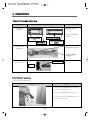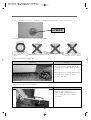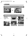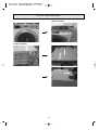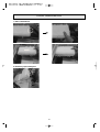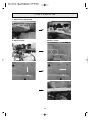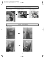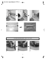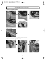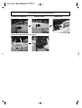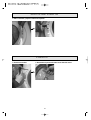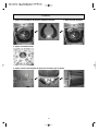
1
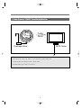
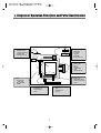
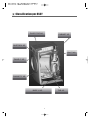
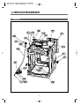
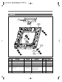
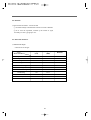
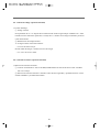
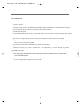
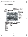
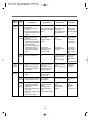
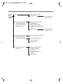
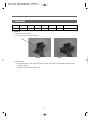
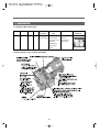
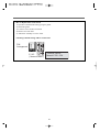
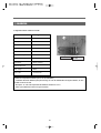
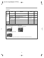
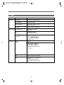
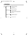
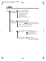
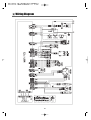
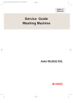
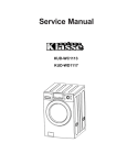
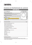
Service Manual
Drum Washing Machine
KUD-WD1133S
DRUM WASHING MACHINE
SERVICE GUIDE
" What is Drum Washing machine.............................................................2
"Product Spec.............................................................................................5
"Diagram of operation Principles and Parts Classification......................6
"Classification per Assy..............................................................................7
"Parts list for each Assy.............................................................................8
"Control Part Function Spec. .....................................................................20
"PCB Pin Arrangement .............................................................................45
"Electronic Parts List Spec. .......................................................................46
"Power Defect.............................................................................................61
"Noise Defect..............................................................................................62
"Wirng Diagram .........................................................................................63
"Installation ................................................................................................64
" What is Drum Washing Machine?
1. Drum Washing Machine
Water consumption is reduced by using the power of the laundry falling (free-fall) created when rotating
the drum resembling a sieve net. With temperature control system, this drum washing machine saves
energy and improves washing performance at the same time.
2. Features of Drum Washing Machine
" Simultaneous supply of cold#hot water
As cold and hot water is supplied at the same time, heating time and energy is saved.
" Top-quality popup dial
The top-quality popup dial is used only during washing process.
" Dust filter
Filter to remove foreign substances, such as naps generated during washing, etc., is installed inside the
drum.
" DD inverter motor
The direct-drive type, of which motor is directly connected to drum without an interim clutch,
significantly reduces noise and vibration.
" Heating device is installed to enable boiling of the laundry.
" Large door creates grand appearance and makes it easy to put in and out the laundry.
" For pump drainage, the powerful pump speeds up drainage process.
2
3. Power System of#KLASSE$Drum Washing Machine
The
Laundry
Turbo
Drum
BLDC Motor
Drainage Motor
#DD Control: Direct drive type of direct connection between drum and motor
#Rotation by powerful high-performance BLDC motor
#Pump drainage type for built-in installation
3
rum Wa
4. Major Functions of Drum Washing Machine
$ Washing
When rotating drum after putting in the laundry and detergent into the drum, the laundry are rotated by
protrusions (lifters) attached inside the drum.
Washing is carried out with bending and impact actions generated by falling of the laundry to the top
part of drum.
% Rinsing
Rinsing cleanly washes out detergent and dirt removed from the laundry after washing cycle.
& Spin-drying
Weak, standard and strong cycles can be selected according to types of fabrics to be washed. Spindrying is carried out by rotation (the centrifugal force) of drum according to the designated speed.
' Drainage
Pump Drainage: Powerful pump for built-in installation and application of filter to remove foreign
substances
4
" Product Spec
Product Spec.
External Measurements (inches)
27"(width) x 31.8"(depth) x 40.1"(height)
Weight
198.4lbm
Rated Supply Power
Rated Consumption Power
120V 60Hz
Washing
200W (1100W during heating)
Washing Method
Drum type
Water Pressure
29kPa ~ 784kPa(0.3kgf/kg~8kgf/kg)
5
" Diagram of Operation Principles and Parts Classification
1. CONTROL PART
• Main PCB
• Front PCB
• Harness
• Noise filter
• Power Cord: 15A
4. WATER SUPPLY PART
• Cold Water: 3 holes
Cold water, pre-washing
• Hot Water: 1 hole
• Water supply box, hose
2. DRIVING PART
• BLDC motor
• Drum
• Bearing
• Spider/ shaft
• Tub
• Weight balancer
3. HEATING PART
• Water Heater: 1000W
• Washing temperature
sensor
5. DOOR
• Door lock S/W
- Lock hinge
• Door AS: Glass
• Gasket
6. DRAINAGE PART
• Drainage pump
• Valve housing
• Hose
7. SUPPORTER
• Base
• Damper AS: 4
• Spring: 2
6
" Classification per ASSY
PLATE TOP AS
CABINET AS
INLETBOX AS
DUCT AS
PANEL F AS
CABINET F AS
BASE U AS
TUB AS
7
" PARTS LIST FOR EACH ASSY
1. CABINET AS
8
No
Part Name
Part Code
Description
Qtt'y
Remarks
C01
CABINET
3610811740
SGCC 0.8t, Painting
1
C02
FRAME LOWER
3612206700
SBHG 1.2T
1
1 Piece SVC
C03
FRAME TOP L
3612206500
SGCC 1.6T
1
part
C04
FRAME TOP R
3612206600
SGCC 1.6T
1
C05
FRAME UPPER
3612208200
SBHG 1.2T
1
C06
STOPPER SPRING
3615202200
POM
2
C07
FIXTURE PLATE
3612008000
POM
8
C08
SCREW TAPPING
7121401211
T2S PAN 4X12 MFZN
8
C09
NOZZLE AIR
3618103110
PP
1
C10
HANDLE CABINET
3612608100
PP
2
C11
COVER BACK AS
3611425530
COVER B + PAD CABINET
1
C12
SENSOR PRESSURE
3614825220
DWD-130RP
1
C13
UNIT DRAIN PUMP AS
36189L5600
PUMP+FILTER
1
3611910200
13KG HANYU FILTER
1
HOSE DRAIN I
3613271300
ST+EL 1,010mm
1
1 Piece SVC
-
ABSORBER HOSE DRAIN
3610115600
T10, 60x130
1
Part
-
CLAMP HOSE
3611203900
SK5 D=26
2
Fix Hose drain I
C15
HOSE WATER REMAIN
3613271410
EPDM, 13kg, UL 3t Round bending
1
C16
CAP WATER REMAIN
3610916800
PP
1
C17
CUFF DRAIN HOSE
3616802600
PP
1
C18
PCB AS
USA WASHER, UL
1
C19
COVER PCB M
3611427700
UL,ABS,VE-0856, MAIN PCB COVER
1
C20
HOSE SIPHON
3613272210
EPDM, 13kg, UL 3t L=270
1
C21
CLAMP HOSE
3611203900
(26
1
-
HARNESS AS
3612796T00
UL, 13kg Wash, Non bubble
1
C13-1 FILTER PUMP
C14
PRPSSWAD24
9
WASHER
rum Wa
2. BASE U AS
B06
B02
B01
B03
B04
B5
No
Part Name
Part Code
Description
Qtt'y
B01
REACTOR
52G043A110
RT-047K,L=150mm
1
B02
BASE U
3610392700
PP
1
B03
SUPPORTER LEG
3615303600
3.0T
4
B04
FIXTURE LEG
3612006400
ABS, DWD-100DR
4
Foot+Special bolt,
B05
FOOT AS
3612100700
Double insert type
4
Hybra-Nylon66
B06
PROTECTOR HEATER
3618304600
10
SECC 0.35T
1
Remarks
3. TUB AS
11
rum Wa
No.
Part Name
Part Code
Qt'y
Specifications
Color
T01
SPECIAL SCREW
3616029400
8
SWCH 8.5x30
NA
T02
BALANCER WEIGHT AS(L)
3616106900
1
13kg Drum
NA
-
BALANCER WEIGHT AS(R)
3616106800
1
13kg Drum
NA
T03
GASKET
3612322000
1
EPDM, 13kg, Wash only
NA
Cost in
USD($)
Remarks
Fix Balance W.to Tub F
Nozzle shower
T04
NOZZLE SHOWER
3618104000
1
PP
NA
T05
CLAMP GASKET AS
T06
TUB FRONT
3611205300
1
Gasket, 13kg Drum
NA
3618828Y00
1
FRPP, 13kg Drum
NA
T07
SPECIAL SCREW(TUB)
3616029800
15
SWCH 6.5x30
NA
T08
LIFTER BODY
361A400700
3
PP, 13kg Drum
Gray
T09
CAP FILTER
3610917310
3
ABS, Non-Nano, 13kg
Gray
-
FILTER
3611908410
3
ABS, Non-Nano, 13kg
Gray
T10
SPRING SUSPENSION
3615114800
2
13KG DRUM
NA
T11
DRUM AS
3617008X00
1
SUS, 13kg
NA
T12
SPIDER AS
361A300600
1
13kg, ALDC+S45C
NA
T13
SPECIAL SCREW(SPIDER)
3616029500
6
STS 430, 8x25
NA
T14
FIXTURE HEATER
3612006700
1
STS 430
NA
T15
DAMPER FRICTION
361A700300
2
AWECO,HP3 60N/
NA
Tub F&R right
T16
DAMPER FRICTION
361A700110
2
70N AKS ST=170-260 DL=197.5
NA
Tub F&R left
T17
DAMPER PIN
361A700200
8
AKS D=14.5
NA
Tub & Base U
T18
HOSE DRAIN
3613269000
1
EPDM,PUMP
NA
T19
CLAMP HOSE
3611203410
2
SK5, D=33
NA
T20
DRAIN HOUSING I
36196TAM00
1
PP, Pump
NA
T21
HOSE AIR TRAP
3613269700
1
EPDM, 13kg Drum
NA
T22
CLAMP HOSE
3611204700
2
SK5, D=26
NA
T23
AIR TRAP
361A500101
1
PP
NA
Fix Tub F & R
STS mesh insert injection
9mm Buffer4.0
T24
HOSE AIR
3613270600
1
ID=3.0, D=8, L=960mm
NA
T25
GASKET TUB
3612321100
1
EPDR FORM, 13kg
NA
T26
TUB REAR
3618828Z00
1
FRPP, 13kg Drum
NA
T27
HOSE AIR
3613266300
1
EPDM,DWD-110RP
NA
T28
CLAMP HOSE
3611203400
2
SK5, MFZN, D=35
NA
T29
UNIT STATOR BLDC
36189L4840
1
30T,36Slot,2Snesor,
NA
T29-1
BLDC HALL IC
3426D01002
1
PCB HOLDER AS
NA
T30
BRACK HOUSING
3610609700
1
SESEN, 2.5T
NA
T31
SPECIAL BOLT AS
3616063400
6
SWCH M8+Silock, 58mm
NA
T32
UNIT ROTOR BLDC
36189L4900
1
Magnet24,Serration,WR1238F001
NA
T33
SPECIAL BOLOT AS
3616029600
1
SWCH,10x30,F/L Bolt,S.P/W
NA
T34
HEATER WASH
3612801740
1
UL.120V1.0KW6.7W/SQ.S
NA
TS.1R3A515003.L/W
12
Fix Stator to Tub R
Fix Rotor to Spider Shaft
4. INLET BOX AS
No
I01
I02
I03
I04
I05
I06
I07
I08
I09
I10
I11
I12
I13
Part Name
AS INLET BOX
INLET BOX
NOZZLE AS
HOSE INLET
CLAMP AS
HOSE WATER SUPPLY
HOSE WATER SUPPLY
HOSE WATER SUPPLY
HOSE WATER SUPPLY
PIPE JOINT(HOSE INLET)
HOSE SHOWER
CLAMP SPRING
VALVE INLET
VALVE INLET
Part Code
3617510700
3617510800
3618104800
3613270300
3611203200
3613270900
3613270900
3613270900
3613270900
3614413300
3613270110
3611203800
3615416701
3615416931
Description
DWD-WD1131
PP
TOP+UNDER )*
EPDM
+60
EPDM, ID9.9 0D14.5 L=410mm
EPDM, ID9.9 0D14.5 L=380mm
EPDM, ID9.9 0D14.5 L=230mm
EPDM, ID9.9 0D14.5 L=530mm
PP
EPDM, ID=8.5 L=550
ID=15.5 T=0.6 B=10
120/60Hz UL BITRON 1WAY
120/60Hz UL BITRON 3WAY
13
Qtt'y
1
1
1
1
2
1
1
2
1
1
1
10
1
1
Remarks
rum Wa
5. CASE DETERGENT AS
A03
A04
A06
A05
A02
A01
No
Part Name
Part Code
Description
Qtt'y
A01
CASE HANDLE
3611145500
ABS
1
A02
CASE DETERGENT
3611145600
PP
1
A03
CAP SOFTENER
3610917800
PP
1
A04
CAP BLEACH
3610917900
PP
1
A05
CASE LIQUID
3611145700
PP
1
A06
CAP LIQUID
3610918000
PP
1
14
Remarks
6. CABINET F AS
F20
F01
F19
F21
F03
F02
F04
F12
F09
F10
F22
F23
F18
F05
F06
F07
F16
F13
F08
F11
F15
F17
F14
15
rum Wa
No
Part Name
Part Code
Description
Qtt'y Remarks
F01
CABINET F
3610811820
SECD 1.0T PUMP
1
F02
SUPPORT HINGE
3615304000
SGCC 1.6T
1
F03
LABEL SAFETY R
3613555800
PVC,130RP'S Cab. F Safety Label
1
F04
LABEL WARNING
3613558500
PVC,130RP'S Cab. F Warning Label
1
LABEL RATING
3613558200
PVC, UL ASKO Rating label
1
F05
FRAME DOOR INNER
3612206800
TB53
1
F06
STOPPER DOOR
3615202300
PP
1
F07
DOOR GLASS
361A110600
GLASS
1
F08
PROTECTOR GLASS
3618304300
ABS(Transparent)
1
F09
HINGE DOOR
3612902900
ALDC
1
F10
CAP HINGE DOOR
3610916500
POM
4
F11
FRAME DOOR OUTER
3612206900
ABS
1
F12
SCREW TAPPING
7115402008
T1S FLT 4x20 SUS430
16
F13
COVER HANDLE
3611426700
ABS
1
F14
HANDLE DOOR
3612609000
ABS
1
F15
HOOK DOOR
3613100800
ZNDC
1
F16
SPRING HOOK
3615113700
SUS ID=4.3, NI=7, D=,0.9
2
F17
PIN HANDLE
3618200100
SUS D=3.0
1
F18
SCREW TAPPING
3616030000
F/L BOLT(SE) 5*12 SUS
4
F19
SWITCH DOOR LOCK
3619046410
DF F11 110 125V 16A PTC-SOLENOID
1
F20
SCREW TAPPING
7122401608
T2S TRS 4X16 SUS 430
2
F21
SCREW TAPPING
3616029950
TTS"S" HEX F/L 4*8
4
F22
CASE PUMP
3611141400
PP
1
F23
COVER PUMP
3611426800
ABS
1
-
16
7. PANEL F AS
No
F01
F02
F03
F04
F05
F06
F07
F08
F09
F10
F11
F12
F13
F14
F15
F16
F17
F18
Part Name
PANEL-F AS
PANEL-F
BUTTON POWER
BUTTON START
SPRING BUTTON
DECO COURSE
WINDOW COURSE
WINDOW DISPLAY
BUTTON FUNCTION
WINDOW FUNCTION
BUTTON OPTION
SCREW TAPPING
BUTTON TIME
PCB -F AS
CUSTOM LED
CASE PCB-F
BUTTON DIAL AS
HOLDER COURSE
HOLDER LED
HOLDER OPTION
Part Code
Description
3614287300 DWD-WD1131
3614287200 ABS + SILK PRINT
3616635900 ABS
3616636000 ABS
3615115700 SUS304
3611685400 ABS
3615504800 ABS(Transparent) (TR558)
3615504900 ABS(Transparent) (UT-0510)
3616636100 ABS
3615505000 ABS
3616636200 TR 558 ABS(Transparent)
7122401411 T2 TRS 4x14 MFZN
3616636300 ABS
PRPAFR9X00 DWD-WD1131
3613052900 ABS
3611145300 ABS(5VB, VE-0856),UL
3616634700 DWD-130RP
3613053000 ABS(5VB, VE-0856),UL
3613053100 ABS(5VB, VE-0856),UL
3613053200 ABS(5VB, VE-0856),UL
17
Qtt'y
1
1
1
1
2
1
1
1
1
1
1
7
1
1
1
1
1
1
1
1
Remarks
rum Wa
8. PLATE T AS
T02
T01
T03
No
Part Name
Part Code
Description
Qtt'y
T01
PLATE TOP
3614533010
SECD 1.2T
1
T02
PLATE SUPPORTER AS
3615304110
ABS + EPDM
2
-
SCREW TAPPING
7122401411
T2S TRS 4x14 MFZN
4
T03
LABEL CAUTION
3613553831
PVC
1
ENERGY GUIDE
3613558310
Energy Label, 13kg Drum
1
-
18
Remarks
rum Wa
9. ACCESSORY
A01
A02
A03
A04
No.
Part Name
Part Code
A01
HOSE DRAIN O AS
3613268500
DWD-800W, L=1,500
1
GUIDE DRAIN HOSE
3612502300
PP
1
HOSE INLET AS
3613271500
REFLEX, PVC 1.3M
1
Cold
HOSE INLET AS
3613271510
REFLEX, PVC 1.3M
1
Hot
A03
UNIT SVC WRENCH
36189L3X00
PO+Coating, 2.3T DWD-110RP
1
A04
MANUAL OWNERS
4589A61600
ASKO Manual
1
A05
CAP HOLDER
3610916400
PP, DWD-10RP
4
A02
Descriptions
A05
19
Qt'y
Remarks
English & French
" Control Part Function Spec
1. SEQUENCE CHART
Normal
Classification
Small
P
r
e
W
a
s
h
W
a
s
h
R
i
n
s
e
S
p
i
n
Sensing
Water Supply
Prewash
Drain
Balancing Spin
Meduim Spin
Sensing
Water Supply
Washing1
(Heating)
Drain
Balancing Spin
Meduim Spin
Water Supply
Rinsing 1
Drain
Balancing Spin
Meduim Spin
Water Supply
Rinsing 2
Drain
Balancing Spin
Meduim Spin
Water Supply
Rinsing 3
Drain
Balancing Spin
Main Spin
Cotton
Sanitary
Processing Time
10sec
2min
10min
8min
1min
2min
3min
20sec
2min
50min
45min
30min 28min
25min
15min
1min
2min
3min
2min
3min
1min
2min
3min
2min
3min
1min
2min
3min
2min
3min
1min
2min
9min
7min
6min
60sec
10sec
1:05
Low
Small
Low
Small
White
53min 57min
37min
32min
20min
16min
17min
Cloths Release
END
Remain Time Display
1:09
53
54
1:30
NOTE
1. Normal : W/C + Wash + Soil Normal + Rinse 2 + Medium Spin
End
Bulky
Low
2. Cotton : W /C + Wash + Soil Normal + Rinse 2 + Ex.High Spin
3. Sanitary : E/C + Wash + Soil Normal + Rinse 2 + Medium Spin
4. Bulky : C/C + Wash + Soil Normal + Rinse 2 + Mediume Spin
5. White : W/C + Wash + Soil Normal + Rinse 2 + Mediume Spin
20
1:34
1:14
1:02
rum Wa
Classification
P
r
e
W
a
s
h
W
a
s
h
R
i
n
s
e
S
p
i
n
Sensing
Water Supply
Pre Wash
Drain
Balancing Spin
Meduim Spin
Sensing
Water Supply
Washing1
(Heating)
Drain
Balancing Spin
Meduim Spin
Water Supply
Rinse 1
Drain
Balancing Spin
Meduim Spin
Water Supply
Rinse 2
Drain
Balancing Spin
Meduim Spin
Water Supply
Rinse 3
Drain
Balancing Spin
Main Spin
Processing Time
10sec
2min
10min
8min
1min
2min
3min
20sec
2min
50min
45min
30min
25min
15min
1min
2min
3min
2min
3min
1min
2min
3min
2min
3min
1min
2min
3min
2min
3min
1min
2min
9min
7min
5min
60sec
10sec
Heavy
Duty
Delicate
Wool
Perm
Press
Speed
Wash
37min
Soak 30min
27min
13min
6min
8min
Cloths Release
END
Remain Time Display
1:44
37
30
1:04
33
NOTE
1. Heavy Duty : W/W + Pre Wash + Wash + Soil Normal + Rinse 3 + High Spin
End
Drum-C
2. Delicate : C/C + Wash + Soil Normal + Rinse 1 + Low Spin
3. Wool : C/C + Wash + Soil Light + Rinse 1 + Low Spin
4. Perm Press : W/C + Wash + Soil Normal + Rinse 2 + Low Spin
5. Speed Wash : C/C + Wash + Soil Light + Rinse 1 + Medium Spin
6. Drum-Cleaning : C/C + Soak + Soil Light + Rinse 2 + Low Spin
21
13min
1:20
2. Composition per Function
2-1. Water Supply
1) Water Temperature Selection
Water supply algorithm differs according to water temperature selected among 5 levels.
In other temperatures, with the exception of cold water, constant temperature control is executed.
Cold water and hot water operation is carried out in turn according to the target temperature.
Water Temp.
Target Temp.
Target 1
Target 2
Extra Hot/Cold
67-
67-
70-
Hot/Cold
41-
40-
42-
Warm/Warm
31-
30-
32-
Warm/Cold
31-
30-
32-
Cold/Cold
-
-
-
2) For Cold/Cold, valve operation does not change according to temperature and only the time unit of cold
on for 7sec and off for 9sec is set to supply cold water per each unit of 16sec.
$ Pre-wash V/V Operation
On for 3sec/ off for 2sec - Twice: Removing residual detergent from water supply box
% During the intial water supply for washing water is received 5mm higher than the set level.
3) How to Insert Bleach
$ During Washing
Operation for 12sec after 3-minute washing in wool, delicate and speed wash courses
Operation for 12sec after 5-minute washing in cotton course
Operation for 12sec after skipping soaking and 4-minute of washing in Drum-cleaning course
Operation for 12sec after soaking and 4- minute of washing in Drum-cleaning course
22
rum Wa
2-2. Drenado
1) Operación de la bomba - ciclo de lavado
$ La bomba trabaja continuamente antes de concluir el drenado
% En el ciclo de exprimido, cauando ya ha sacado el agua,
enciende por 18sec y apaga por 3sec
2-3. Detección del Sensor
1) Sensor de nivel de agua
. Datos de nivel de agua
Classification
Height
Frequency
(mm)
(KHz)
Spec. Small
130
24.62
Spec. Low
130
24.62
Washing Small
130
24.12
Washing Low
130
23.84
Standard Rinsing
160
24.17
Rinsing
160
23.3
Additional Rinsing
175
23.92
Tub Washing
195
23.77
Overflow
260
22.6
Safety
125
24.7
Reset
125
24.68
Water Level
23
Remarks
2) Sensor Temperatura de lavado
$ Resistencia estándar of 4.7/-49°C…
% Datos Sensor de Temperatura
Resistance(0)
Voltage
0
35.97
0.58
10
22.76
0.86
20
14.77
1.21
22
13.57
1.29
24
12.48
1.37
25
11.98
1.41
27
11.04
1.49
29
10.18
1.58
30
9.78
1.62
32
9.04
1.71
34
8.36
1.80
36
7.74
1.89
38
7.17
1.98
40
6.65
2.07
49
4.7
2.50
55
3.85
2.75
60
3.24
2.96
65
2.74
3.16
75
1.99
3.51
Temp. ºC
24
Remarks
rum Wa
2-4. Control de Voltage (operación anormal)
1) Control deVoltage
$ Voltage Normal
El acoplamiento de V. C.C. después de la rectificación de onda es registrado por el IPM de 310 ~ 330V.
Cuando el motor comienza la operación, el voltaje de C.C. cambia con la energia consumida y la fuerza
contra elecrtomotriz.
% Identificacion de Voltage anormal
A. Al llegar la fuerza contra electromotriz
1 En caso de 450V o mayor
B. Falla subita de energía / consumo excesivo de energía
1 En caso de 185V o menor
2-5. Control de Corriente (operación anormal)
1) Detección de Corriente Anormal
$ Corriente Anormal de CC atraves del IPM, medida durante la rotación del motor a alta velocidad
10A~12A o mayor
% Detección de Corriente Anormal.- Guarda el valor mas alto registrados y promedia entre los valores
actuales inmediatos y actualiza dichos datos.
25
2-6. S/W de Puerta
1) Operacion del S/W de Puerta
$ Seguro de puerta
3s. después de la operación del bimetal del S/W de puerta , debe pulsar 20msec el solenoide hasta bloquear la
puerta. El bimetal inicia la operación al presionar el boton de encendido.
% Desbloqueo de Puerta
La placa bimetálica del S/W se apaga y el pulso de 20msec en el solenoide se registra hasta que abra la puerta.
& El motor o cualquier parte comienza la operación solamente cuando la puerta es bloqueada.
' La puerta es cerrada si la temperatura medida poe elsensor es mde 55 ºC o mayor, oel nvel de agua
está por arriba del nivel de seguridad.
2 La puerta se puede abrir inmediatamente cuando el ciclo finaliza.
3 Durante una pausa, la puerta se puede abrir si la temperatura y el nivel de agua lo permiten.
2) Desbloqueo de puerta
$ Para agregar alguna prenda durante el lavado, la puerta puede ser abierta, presionando PAUSA y posteriormente
el boton DESBLOQUEO.
% El sistema de desbloqueo de puerta inicia la secuencia para obtener las condiciones de segurida
de nivel o temperatura que permitan abrir la puerta
26
rum Wa
2-7. Sensor de carga
1) El Sensor de carga determina el nivel de agua
$ Realiza la detección de carga al seleccionar; Normal. Cotton, Sanitary.
% La detección se realiza con la carga seca, antes de iniciar el ciclo de lavado.
& Cuando el motor opera a 75 r.p.m por 10sec, la carga es medida con los datos registrados.
2) Sensor de carga para exprimido/secado
$ La detección se realiza con la carga mojada, en el primer exprimido, al final del
ciclo de lavado
% Al operar el motor a 75 r.p.m por 10sec, determina la carga con los datos de salida del motor.
& Los valores bajos para el desbalanceo y exprimido principal se seleccionan según la carga
en base a los datos de salida del motor
2-8. Child Lock
$ Child lock mode begins by pressing 'Beeper' button during cycle.
% In child lock mode, all buttons, with the exception of power button, are not operated.
& In child lock mode, cycle display window is lit to show that child lock has been applied. Also, the
remaining time is displayed in '18:88' window.
' Lock mode is cleared by pressing 'Beeper' button as was done when starting child lock mode.
27
3. Functions per Cycle
3-1. Washing Cycle
1) Classification of Washing
$ Pre-washing and soaking are carried out before main washing cycle.
% Decided value refers to water level and time decided by load sensing in standard, boiling and thrifty
boiling courses. In other sources, it means the pre-set time according to the designated water level.
& Soaking is the cycle consisted with water supply and washing only. Main washing begins
immediately after this cycle without drainage.
' In pre-washing and soaking cycles, only cold water is used and heating is not administered.
2) Heater Operation
$ Washing heater does not re-operate once turned off after reaching the set temperature.
% Even when target water temperature is not reached, washing cycle is finished when washing time
expires.
3) Re-supply of water
$ Re-supply is carried out in case water level detected per 2 minute after water supply completion is
lower than the set water level.
% Motor is stopped during re-supply.
& During washing, re-supply is carried out up to 10 times. After the 10th time, re-supply is not
administered even if water level drops.
' Re-supply is not carried out if more than half of washing time has passed and heater is turned off.
28
rum Wa
3-2. Rinsing Cycle
1) Water Supply Cycle
$ When selecting 'add water for rinsing', water is supplied to the water level of additional rinsing.
% Only cold water is supplied in rinsing cycle.
& In the last rinsing, fabric softener is inserted by opening both cold water V/V and pre-washing V/V at
the same time.
2) Re-supply of Water
$ Water level is checked 1 minute after starting of rinsing cycle. Then, water is re-supplied up to the
designated water level.
3) Drainage
$ To administer drainage after completing washing at water temperature of 55- or higher, drainage is
carried out after dropping water temperature by supplying cold water to high level.
% When drainage cycle begins, drainage motor is continuously kept on.
4) Interim Spin-drying
$ Interim spin-drying is administered up to the r.p.m designated per each course.
The following cycle begins if R spin-drying is not reached after 20 times of balance spin-drying.
% After completion of washing cycle, load sensing is carried out before the first interim spin-drying to
detect load. Then, the cycle proceeds to main spin-drying by differing standard unbalance values
according to the load.
29
3-3. Spin-drying Cycle
1) Drainage
$ Drainage set time is 1min.
% When drainage is completed, 1 minute is reduced from the overall cycle.
2) Balance Spin
Motor running during balance spin
$ Spreading the laundry : Rotating the same 45rpm with left and right direction altematively.
% Attaching stop : Attaching the laundry to drum inside with constant speed.
& Unbalance checking point : First step, check the U.B at 95 rpm, 160rpm
Second step,check the U.B at 95 rpm, 350rpm
Third step, at 300rpm. if the unbalance data is over the criterion
This process will be rpeated
' Drain step : Drain at water around 160rpm
2 After drain, check the unbalance data again. This is so-called balance spin step.
3) R (Real) Spin-drying
$ 'R spin-drying' refers to the process until completion of spin-drying after B spin-drying.
% The r.p.m reached differs according to the spin-drying cycle selected.
& When acceleration ends during spin-drying, constant-speed operation is carried out at the r.p.m set in
the selected cycle. Breaking is carried out after deceleration to app. 450 r.p.m.
' When stopping cycle by pressing temporary stop button during spin-drying, breaking is carried out to
stop motor.
2 Max. r.p.m operation time according to spin-drying selection
Spin-Drying Classification
Max. r.p.m
Time of Max. r.p.m Maintenance
Low
Medium
High
Extra High
550 r.p.m
790 r.p.m
990 r.p.m
1050 r.p.m
330sec
270sec
40sec
10sec
4) No Drainage
$ Cycle is completed without drainage after rinsing is finished
30
Remarks
rum Wa
3-4. Ending
1) Untwisting
$ This cycle aims to prevent creasing by loosening the laundry attached to the inner wall of drum after
completion of spin-drying. Untwisting is carried out for 30sec.
% Motor is operated according to the water stream of untwisting.
2) Ending
$ After completion of untwisting, buzzer is sounded for 10sec and power is turned off.
% In case additional drying cycle has been set, drying cycle is carried out after untwisting.
& After ending process begins, door lock is cleared.
31
4. Button Functions
4-1. Power
1) This electronic power switch turns on/ off display.
2) Automatic Power Switch Off
$ Power is turned off immediately after completion of entire cycles or the selected cycle.
% Power is automatically turned off in 10 minutes if no button control is made after power on.
3) Initial Display for Power Only
$ All course LED is turned on
% 18:88 LED displays '---'.
4-2. Start/Pause
1) Normal course begins when pressing button after turning on power S/W.
2) Operation begins by pressing button after setting a program course or automatic course of 11 varieties.
3) If button is pressed during operation, blinking of cycle lamp changes to lighting only and operation
stops. When button is pressed again, operation restarts from the point of temporary suspension.
4) If cycle is changed by controlling button or encoder switch in temporary suspension state, the mode is
changed to the initial mode.
5) Lock is cleared if in the corresponding conditions by judging values of washing temperature sensor or
water level during temporary suspension.
32
rum Wa
4-3. Wash/Rinse
1) Range of temp. selection differs according to the course selected. (Refer to washing functions per cycle.)
2) The front part of text displayed indicates water temperature for washing and the back part indicates
water temperature for rinsing.
ex) Warm / Cold
Warm : Water temperature for washing
Cold : Water temperature for rinsing
3) Cold water and hot water supply method differs according to water temperature selection. Heating
temperature also differs.
4) For sanitary course, water temperature is fixed at 'Extra Hot/Cold'. When pressing water temperature
button during temporary suspension, buzzer is sounded and water temperature selection is not made.
5) Even in sanitary course, water temperature selection can be made during rinse spin from 'Warm/Warm' to
'Cold/Cold'.
4-4. Spin Speed
1) When pressing button, LED is repetitively lit in the order of " Medium 4 High 4 Extra High 4
No Spin 4 Low'.
2) If drying cycle is selected, operation is carried out as extra high regardless of spin selection.
3) 18:88 display shows the remaining time.
4) During cycle, selection change is possible after temporary suspension.
33
4-5. Soil Level
1) When pressing button, LED is repetitively lit in the order of " Normal 4 5 4 High 4 Off 4 Light 4
5'
2) Soil level can be selected only when washing cycle is set.
3) Soil level is operated in courses other than 'Drum Cleaning', 'Wool' and 'Speed Wash'.
4) Washing time changes according to the selected soil level.
ex) In case of normal course, water temp. of Warm/Warm and water level of 'low' In the order of Soil
Level 'Light - 5 - Normal - 5 - High', washing time changes in the order of '18min - 23min - 28min
- 31min - 33min'.
5) Selection can be changed during cycle after temporary suspension.
6) Overall cycle time is shown in 18:88 display.
4-6. Beeper
1) Beeper button operates in 5 steps.
Changing in the order of 'HIGH--> 5 --> Low --> 5 --> Beeper Off'.
2) After change, it is saved in EEPRPM.
4-7. Delay Wash
1) Preset time indicates ending time of the entire cycle.
2) When pressing preset button, time changes in the order of 24 34 44 6 4 124 2.
3) After selecting preset time, cycle change is possible before entering preset mode by pressing start/
temporary stop button.
However, cycle cannot be changed after entering preset mode.
34
rum Wa
4) To preset operation, select cycle 4 select preset time 4 press start/ temporary stop button.
5) The selected cycle is displayed for 3 seconds when pressing start/ temporary stop button after entering
preset mode to check the selected cycle.
6) Preset is not possible in wool, delicate and drum cleaning courses.
4-8. Pre-Wash
1) Button is operated only when washing is selected.
2) Pre-wash is not available in wool, speed wash and drum cleaning courses.
3) When pressing button, pre-wash is added and LED is lit. LED is turned off when pressing the button
again.
4) Pre-wash LED is turned off when pre-wash is completed.
4-9. Rinse+Spin
1) Rinse + spin is not available in drum cleaning course.
2) When pressing button, rinsing once + spin medium is selected.
3) Operation does not return to previous cycle even when pressing the button again. The cycle set in the
corresponding course is displayed by rotating course dial. Then, rinse spin LED is turned off.
4) Water temperature can be selected with Temp. button after rinse + spin is set.
Selection can be made from Cold/Cold to Warm/Warm.
5) Even after rinse + spin is selected, water temperature selection cannot be made in wool and drum
cleaning courses.
6) When cycle is completed, LED is turned off.
35
4-10. Extra Rinse
1) Extra rinse is not available in speed wash and drum cleaning courses.
2) When pressing button rinsing cycle is added by once and LED is lit. When pressing button again, rinsing
cycle decreases by once and LED is turned off.
3) Extra rinse LED is turned off when rinsing is completed.
4-11. Extra Wash
1) When pressing button, washing time increases by 8min in heavy duty and sanitary courses.
2) When pressing button, washing time increases by 5min in normal and cotton courses.
3) Extra wash is not available in wool, drum cleaning, delicate and speed wash courses.
4) Extra wash LED is turned off when washing is completed.
4-12. Night Time
1) When pressing button, spin speed is set as low and interim spin-drying changes from 790r.p.m to
550r.p.m.
2) When pressing button again, set values of interim spin-drying and main spin-drying mode courses are
resumed.
3) LED is turned off when the cycle is completed.
36
rum Wa
4-13. Custom Program
1) When pressing custom button for the first time, the memorized program is loaded and shown in display
window.
To identify whether it is a memorized program and if custom button has been pressed, 'CEP' and cycle
time are displayed in turn in '18:88' display window.
Overall time is displayed only when cycle begins with start button.
2) When custom program is temporarily stopped and custom button is pressed again, basic cycle of normal
course is set. Water level and load are set as well.
'18:88' display window shows the overall time.
3) Set values are saved when pressing start button in custom mode.
4) Custom setting is administered in the following order.
- Power on --> custom button on --> course and cycle selection --> start button on ==> saved
4-14. Course Selection Switch
1) Normal course selected by clicking switch once after power is turned on.
2) Per each click after the first, course is selected in the direction of CW or CCW.
3) 18:88 display indicates cycle time of each course.
37
4-15. Option Button
Temp
Spin
Soil
Beeper
Delay
PreWash
Wash
White
Wool
Cold/Cold~
NoSpin ~
Light~
Off~
Hot/Cold
ExtraHigh
Heavy
High
Cold/Cold
NoSpin ~
Light
Low
Delicate
Permpress
Cotton
Normal
Heavy Duty
Bulky/Large
Sanitary
Speedwash
Drum
Cleaning
Off~
Medium
Heavy
High
Cold/Cold~
NoSpin ~
Light~
Off~
Hot/Cold
ExtraHigh
Heavy
High
Cold/Cold~
NoSpin ~
Light~
Off~
Hot/Cold
ExtraHigh
Heavy
High
Cold/Cold~
NoSpin ~
Light~
Off~
Hot/Cold
ExtraHigh
Heavy
High
Cold/Cold~
NoSpin ~
Light~
Off~
Hot/Cold
ExtraHigh
Heavy
High
Cold/Cold~
NoSpin ~
Light~
Off~
Warm/Warm
Medium
Heavy
High
NoSpin ~
Light~
Off~
ExtraHigh
Heavy
High
Cold/Cold~
NoSpin ~
Warm/Warm
Medium
Cold/Cold
NoSpin ~
Low
Rinse
Night Custom
Wash
Rinse
+Spin
Time Program
O
O
O
O
O
O
O
O
O
O
O
O
O
High
Light~
ExtraHot/C
O
Extra
Off~
NoSpin ~
Cold/Cold
O
Extra
Light
O
O
O
O
O
O
O
O
O
O
O
O
O
O
O
O
O
O
O
O
O
O
O
O
O
O
O
O
O
O
O
O
O
O
O
O
O
O
O
O
O
O
O
O
O
O
O
Off~
O
High
Light
Off~
High
38
rum Wa
5. MODO DE PRUEBA MANUAL
- La PCB y otras partes electrónicas pueden probarse sin llenar agua y comprobar su estado.
1) Proceso
: Presione encendido > mantenga presionado "WASH" mientras presiona 3 veces "SPIN" > "XXX" ser á
mostrado encienden LED´s y display> cuando presione "Beeper" 1 vez, sucederá la secuencia siguiente.
- "X X X' : Muestra la versió del programa
Step
Display
Details
1
L_C
Door Lock Close
2
run
001
Running times count
3
E5
0
E5 Error count
4
E6
0
E6 Error count
5
E7
0
E7 Error count
6
E8
0
E8 Error count
7
F
Do not use
8
H
Hot Valve on
9
C
Cold Valve on
10
P
Pre Wash Valve on
11
d
Do not use
12
b
Bleach Valve
13
dr
Drainage pump on
14
L_O
Door Lock Open
2) Mas detalles
- Cuando regresa a señal 'LOCK' , todos los procesos están operando normalmente.
- Para probar el motor BLDC programe exprimido o enjuague.
39
6. Notificación de Anormalidad
6-1. IE (Error de entrada) - Error en llenado
1) Causa
$ En caso de no alcanzar el nivel de agua en 5 minutos durante el llenado.
2) Todos los LED´s se apagan y 'IE' se muestra en el display.
3) La alarma sonará por 10 segundos cada 10 minutos.
4) El error en el display se borra al apagar la lavadora.
6-2. OE (Error de salida) - Error en drenado
1) Causa
$ En caso que el nivel del agua no alcance el punto de reajuste después de 10 min. de inicio del drenado.
2) Todos los LED´s se apagan y 'OE' se muestra en el display.
3) La alarma sonará por 10 segundos cada 10 minutos.
4) El error en el display se borra al apagar la lavadora.
6-3. UE (Error de desbalanceo)
1) Causa
$ En caso de no alcanzar el balenceo en el expimido principal en 20 intentos por balancear la carga.
% En caso que el balanceo falle en exprimido intermedio, 'UE' se muestra mientra se mueva al siguiente
proceso.
2) Todos los LED´s se apagan y 'UE' se muestra en el display.
3) La alarma sonará por 10 segundos cada 10 minutos.
4) El error se borra al abrir la puerta y acomodar la carga, cierre la puerta y continue el ciclo, presione
INICIO, el exprimido inicia nuevamente.
40
rum Wa
6-4. LE (Error de Seguro) - Puerta abierta
1) Causa
$ Cuando al oprimir "INICIO" la puerta está abierta y el SW no es activado.
2) Todos los LED´s se apagan y 'LE' se muestra en el display.
3) La alarma sonará por 10 segundos cada 10 minutos.
4) El error en el display se borra al apagar la lavadora.
6-5. E1 - Error en nivel de agua
1) Causa
$ Si el nivel de agua es menor del nivel de reajuste o desbordamiento, se detecta en el llenado.
2) La valvula de entrada trabaja hasta que el agua alcanza el nivel de reajuste.
3) Todos los LED´s se apagan y 'E1' se muestra en el display.
4) La alarma sonará por 10 segundos cada 10 minutos.
5) El error en el display se borra al apagar la lavadora.
6-6. E2 - Error de Sobrellenado
1) Causa
$ Si el nivel del agua en la tina esté sobre el nivel de desbordamiento debido a la operación continua
de la válvula de agua.
2) La bomba de drenado funcionará hasta que el agua esté debajo del nivel de reajuste.
3) Todos los LED´s se apagan y 'E2' se muestra en el display.
4) La alarma sonará por 10 segundos cada 10 minutos.
5) El error en el display se borra al apagar la lavadora.
41
6-7. E4 - Fuga de agua durante el lavado
1) Causa
$ Si el nivel de agua es menor, re-abastece hasta en 15 ocasiones, antes de terminar el calentamiento
del agua.
2) Todos los LED´s se apagan y 'E4' se muestra en el display.
3) La alarma sonará por 10 segundos cada 10 minutos.
4) El error en el display se borra al apagar la lavadora.
6-8. E9 - Sensor de Presión anormal
1) Causa
$ En caso que la frecuencia del sensor de nivel de agua sea menor a 15KHz o mayor de 30KHz en el ciclo
de lavado debido a falla del sensor.
2) Todos los LED´s se apagan y 'E9' se muestra en el display.
3) La alarma sonará por 10 segundos cada 10 minutos.
4) El error en el display se borra al apagar la lavadora.
42
rum Wa
6-9. Motor-related Error
1) E5 (DC-Error de alto voltaje)
$ Si el VCD en el acoplamiento IPM sube a 450V o mayor.
% El motor se detiene y 'E5' se muestra en el display.
& La alarma sonará por 10 segundos cada 10 minutos.
' El error en el display se borra al apagar la lavadora.
2) E6 (EMG) Error
$ En caso de detectar una corriente de 20A o mayor en el puerto EMG
% El motor se detiene y 'E6' se muestra en el display.
& La alarma sonará por 10 segundos cada 10 minutos.
' El error en el display se borra al apagar la lavadora.
3) E7 (Error de Dirección)
Si la señal en HALL IC es diferente de la señal prevista según la dirección de la rotación.
% El motor se detiene y 'E7' se muestra en el display.
& La alarma sonará por 10 segundos cada 10 minutos.
' El error en el display se borra al apagar la lavadora.
4) E8 (Error al iniciar operacion)
$ Si la senal de entrada del Hall IC es anormal debido a problemas en conector del motor.
% El motor se detiene y 'E8' se muestra en el display.
& La alarma sonará por 10 segundos cada 10 minutos.
' El error en el display se borra al apagar la lavadora.
6-10. Error en Sensor deTemperatura
1) H2 Error en sensor de temperatura de lavado
$ Sensor de temperatura de lavado abierto o en corto.
% La alarma sonará por 10 segundos cada 10 minutos.
& El error en el display se borra al apagar la lavadora.
2) H4 Error de sobrcalentamiento en lavado.
$ Si la temperatura de lavado detectada por el sensor es de95- o mayor.
% La alarma sonará por 10 segundos cada 10 minutos.
& El error en el display se borra al apagar la lavadora.
43
3) H5 Error en la temperatura para ciclos de lana y delicados.
$ Si la temperatura del agua en ciclo de lana o delicados es de 45- o mayor.
% La alarma sonará por 10 segundos cada 10 minutos.
& El error en el display se borra al apagar la lavadora.
4) H6 Error en Calefactor de Lavado.
$ Después de 15 min. inicia la operacion del calefactor.
Si la temperatura es de 42ºC o menor y no aumenta en 2 ºC o más. En caso de que la temperatura sea
de 42 ºC o mayor y no aumenta 1- o mas.
% Si la temperatura baja 2- o mas debido a un reajuste en el nivel de agua, etc. la temperatura
y el tiempo de 15 min. para señalar el error se reajustan.
& La alarma sonará por 10 segundos cada 10 minutos.
' El error en el display se borra al apagar la lavadora.
5) H8 Error de sobrecalentamiento en lavado
$ Si la tempratura del calefactor de lavado se incrementa 5- o mas en un lapso de 30 sec.
sin agua en el tambor.
% La alarma sonará por 10 segundos cada 10 minutos.
& El error en el display se borra al apagar la lavadora.
6) PFE (Error en filtro de bomba)
$ El ciclo se brinca al siguiente paso cuando no alcanza el 70 % de r.p.m. durante el exprimido
intermedio.
% El programa puede balancear la carga en el exprimido cuando alcanza el 70% de las r.p.m de la velocidad
seleccionada durante el exprimido principal.
& 'PFE' error ie causado cuando el tiempo de drenado se incrementa.
' El error en el display se borra al apagar la lavadora.
44
" PCB PIN ARRANGEMENT
45
" Electronic Parts List Spec.
1. VALVE INLET
Classification
3-hole Valve and Hot Water Valve
Code
3-hole: 3615416940, Hot Water: 3615416700
Color
Gray
Coil Resistance
4320 ~ 5280 $
Use
Supplying water for washing/ pre-washing and bleach
Appearance
Bleach Input Valve
Structure
Hot Water Input Valve
Washing Water
Input Valve
Pre-washing
Water
Input Valve
Symptoms of
Breakdown
Water not
supplied
Detailed
Symptoms
Cause
Water supply not Water tap not opened
carried, only noise Coil short
is heard
Excessive foreign
substances in SUS filter
Foreign substances in
valve
Water supply not Connector loosened
carried out without Coil short
noise
Wiring short
Continuous water Defect in water level
Water is
continuously supply in power sensor
'on' state
supplied
Defect in pressure hose
(inside tub) Continuous water Defect in water supply
supply in power valve
'off' state
Defect in water supply
Water leakage
Others
valve assembly, etc.
through sides
Diagnosis of Defect
Check for tap opening.
Check if resistance between water supply valve terminals is
within 4320~5280$.
Remove water supply hose and check for foreign substances in
filter.
Visually check connector connection status.
Check if resistance between water supply valve terminals is
within 4320~5280$.
Wiring short -> Conduction test
Refer to water level sensor defect check method.
Check for blocking of holes in pressure hose.
Check for leakage through the sides of water supply valve.
46
Solution
PCB Error
Mode
Open water tap.
"IE"
"IE"
Clean out foreign substances
from inside the filter.
Replace water supply
valve.
Administer re-insertion.
Replace water supply
valve.
"IE"
Replace water level
sensor.
Replace defect parts.
Replace water supply
valve.
Replace water supply
valve.
"IE"
"IE"
"IE"
"IE"
"E2"
"E2"
-
rum Wa
Water supply not
carried out (IE)
Defect in
Water
Supply
Continuous water
supply (IE)
• Suspension of water supply
• Tap frozen
• Tap closed
• Hot & cold water hose switched for connection
• Low water pressure (0.2kgf/cm or less)
• Blocking of water supply valve filter by foreign substances
• Defect in cold & hot water valve
• Defect in connection of water supply terminal (not connected)
• Defect in pressure switch
• Defect in water supply relay drive circuit
• Defect in PCB
• Water supply relay open
• Defect in water supply valve
• Leakage in air hose (air leakage from pressure switch hose)
• Air trip blocked, damaged
• Defect in pressure switch
• Defect in drainage valve: Continuous water supply
• Blocking by foreign substances in drainage bellows
• Defect in PCB
• Water supply relay short
Immediate water
supply when power
is turned on
• Defect in PCB
Water supply
continued when
power is turned off
• Defect in water supply valve
47
• Water supply relay short
Symptoms of Inspection
Spot
Breakdown
Water
supply not
carried out
Inspection Method
Inspection Result
Problem Identified
1) Suspension of water supply
2) Water tap locked
3) Cold-hot water hose incorrectly
- Cold/ hot water hose switched -Defect in cold/ hot water
connected
-Large amount of rust, sand and hose assembly
4) If no defect is found, dismantle water dust, etc.
-Defect in cleaning of water
supply hose and check water supply
supply filter (blocked)
valve filter.
Water 1) Measure coil resistance in water
supply valve supply valve.
2) Remove top cover and visually
check for separation of water supply
valve terminal connector and wiring
short/ connection status.
3) In case water valve operation sound
is heard, but water supply is not
carried out, check for blocking of
water supply valve or restraint on
plunger.
Pressure 1) Check for ‘E9’ in display window.
Switch
Repair Method
-Assemble cold/ hot
water hose correctly.
-Clean water supply filter.
-Replace water supply
valve.
-Try reconnection or
remove elements of
connection defect.
-5.3kW or higher
-Coil short
-Connector loosened/ not
inserted
-Connection defect
-Electric wire short
-Sound and defect in water
supply due to foreign
substances in bellows
-Electric wire short
-Structural defect in water
supply valve
-Try reconnection or
remove elements of
connection defect.
-Replace water supply
valve.
-E9
-Loosening of pressure S/W
terminal or electric wire
short
-Defect in pressure S/W
-Connect terminal of
pressure S/W.
-Connect terminal of
PCB.
-Replace pressure S/W.
Water
supply not
carried out
PCB
1. Check PCB pin connector insertion
status.
2. Power is supplied to water supply
valve terminal, but water supply is
not administered.
Electric wire easily loosened
when tugged
PCB water supply circuit open,
damaged (water supply relay
operation not carried out)
Pin connector housing not
inserted
Defect in water supply circuit
Completely insert
connector housing.
Replace PCB.
Continuous
water supply
PCB
1. Immediate supply when power is
turned on
PCB water supply circuit or
relay short (continuous
conduction to valve)
Water supply relay short
Replace PCB.
Defect in water supply valve
Replace water supply
valve.
Water 1. Check if water supply is continuously Water supply bellows
supply valve carried out even if power is not on. blocked/ deformed
Drainage 1. Check for normal operation of water -Not closed due to foreign
-Foreign substances in valve -Remove foreign
drive motor
supply valve/ water supply status.
substances.
housing
substances inside drainage
(valve 2. Check if water is drained through
-Remove foreign
-Foreign substances
housing
housing)
drainage hose.
substance.
-Defect in drive motor
-Wire caught by foreign
3. Check for foreign substances inside
-Replace drive motor.
restoration
substances outside drive
valve housing.
motor
4. Check for foreign substances in drive -Forced restoration not possible
motor wire.
5. Forcefully restore SUS wire.
48
rum Wa
%&!Water Level Sensor
1) Spec. of Water Level Sensor
O/F: Forced drainage is
necessary as water
level is high. When
this level is reached,
water supply must be
stopped and drainage
must be forcefully
administered.
RESET :
Low: Small load of laundry, therefore considered to be
water level of 'low'
1. Spin-drying begins
30sec after drainage
level reset is reached.
Medium: Large load of laundry
Medium High: Water level for rinsing
2. Heater operation level
Safety: Door open possible
Door opened only when water level is below
safety level
Model
WD1132
Code
Classification
O/F
Medium High Medium
3614825220
Frequency
22.607
23.107
DN-DD03,
Water level
DL-DW03
(mm)
260915
225915
Low
Safety
Reset
Initial(Defect) Inlet Angle
23.207
24.007
24.407
24.707
25.807
22097
170915
140915
120920
0
908
2) Breakdown Analysis
Symptoms
Detailed Symptoms
Cause
Diagnosis
Solution
PCB Error
Mode
Continuous Water valve normal
water
supply
"E9"
Occurrence in water level
sensor
30kHz or higher
Defect in pressure sensor
hose
Check for holes.
Replace hose.
"E2"
Blocking of pressure sensor
hose
Visual checking
Remove foreign substances.
"E2"
Connector loosened
Visually check connector
connection status.
Administer re-insertion.
"E9"
Wiring short
Wiring short ->
conduction test
49
"E9"
Defect in
Water
Level
Detection
E9
• Defect in pressure sensor
• Defect in PCB
• Defect in water level
detection circuit
• Water supply greater than
the selected water level
• Continuous water supply
in high water level
• Pressure sensor hose bent or
partially blocked
• Defect in pressure sensor
• Air leakage from pressure sensor
hose
• Defect in water level
• Defect in PCB
detection circuit
• Water supply smaller than
the selected water level
• Reset level not detected
• Foreign substance in air trip inlet
• Water level detection too
high or low
• Defect in pressure sensor
(damage in oscillation
condenser)
• Foreign substances in air
trip inlet
• Defect in PCB
• Low frequency of pressure
sensor water level
• Defect in PCB
50
rum Wa
'&!POWER CORD
Classification
Rated
Cord Thickness
Color
Code
Type
Length
Remarks
DEC
250V/15A
1.5sq
Gray
3611340430
LP-31 SJT
2.3m
-
1) Assembly
. 4 embossed parts in cabinet
-> To prevent loosening after assembly
[Before]
[After]
. CONNECTOR
-> #1806 Housing 3P Used: Using both ends only and not the hole in the middle (materials highly
resistant to flame)
-> To prevent fire caused by high current
51
(&! DOOR LOCK S/W
1) Comparison of Door Lock S/W Spec.
TYPE
CODE
MODEL
RATED
LOCK ON
PRINCIPLE
LOCK 'ON'/'OFF'
TIME
LOCK OFF TYPE
DF F01 007 3619046410 WD1132 125V 16A Bimetal operation -ON : Min. of 6sec
1. Forced OFF by
by PTC heating -OFF after Cooling
solenoid
in Air: 40sec ~ 5min 2. Natural OFF by
-Forced OFF:
cool down of
Immediate OFF
(door opening)
bimetal
2) Structure and Spec. of Door Lock S/W: DF SERIES
52
EXTERNAL
APPEARANCE
r
* How to Replace Door Lock Switch
1) Open door and dismantle clamp spring for gasket.
2) Dismantle gasket.
3) Loosen 2 screws for door lock S/W.
4) Remove door lock S/W.
5) Administer assembly in reverse order.
* Checking Solenoid Wiring of Door Lock Switch
PIN
Arrangement
2345
(1 does not exist.)
Terminal 3 and 4:
Normal if 156 ~ 234
53
* DF Door Lock S/W Operation
Cause
Ruido
Tic-tac
Al iniciar operación
y en pausa cuando
el nivel de agua es bajo
se oye un tic-tac
Ruido normal
Sonido ocasionado durante la operacion del solenoide
al deslizarse el disco de la leva para liberar o bloquear
la puerta
LE'
Ruido de tic-tac y el
display muestra 'LE'
Conector zafado
Revise el estado del conector del SW de Inserte conector.
puerta
"LE"
Terminal zafada del
conector
Ver desarme del SW y revisar conexión
de terminales
Inserte terminal
del S/W 4 o 5
"LE"
Puerta no cierra
completamente
- Revise estado de la puerta o
posible obstrucción
Cierre bien
la puerta
"LE"
Daño en gancho de
puerta
-
Cambie gancho
"LE"
Defecto en operación
de leva reten
Constante ruido de 'tic tac' anormal del
bloqueo y desbloqueo de puerta
Cambie S/W.
"LE"
Conector zafado
Compruebe visualmente el estado
del conector del SW
Corrija conexión.
"LE"
Terminal zafada del
conector
Ver desarme del SW y revisar conexión
de terminales
Inserte terminales
del S/W 2 o 3
"LE"
Bobina del solenoide rota
Revise resistencia (ver página anterior)
Cambie S/W.
"LE"
1. 'LE' se muestra
en panel sin ruido de
'tic-tac'
Puerta no
abre.
Diagnostico o Defecto
Solution
Error
Mode
Symptoms Detalle de Sintoma
–
Falla de energía
durante la
operación
Si falla la energía durante la operación el S/W queda bloqueado, la PCB MICOM' no puede
abrir la puerta. debe esperar como max. 5 min.
Sin haber falla de
energía.
Agua en tambor
Others
Door does not open normally in case of loosening of connector/ terminal and breaking of
solenoid coil during operation. Administer measures after test according to the following method.
Revise si el nivel de agua está arriba
del nivel de seguridad
54
Puerta abre
despuées de drenar
–
r
)&!CALEFACTOR
1) Especificaciones calefactor lavado
Classification
Wahing
Maker
IRCA
Voltaje
120V
Potencia
1000W95%
Power
Resistencia
25.47ohm
Current Density
8.9
Fusible de Temp.
184-
Thermister
Heater built-in
Calefactor lavado
Sensor Temp.
Lavado
MaterialSUS430
Max. Temp.
Water
Part Code
3612801740
Fusible de Temperatura de lavado (184 °C No se reestablece)
: Localizado dentro del calefactor para prevenir fuego, en caso de calentamiento sin agua en tambor, en caso
de falla en sendor de nivel.
: Abre aprox. en 1min si la temperatuar del calefactor alcanza los 270 °C
: Indica que el calefactor funcionó sin agua en tambor.
55
r
2) Diagnóstico
Síntoma
de falla
Causa
Diagnóstico
Solución
PCB
Error
Arnés en corto
Revise arnés
Repare arnés
"H6"
Calefactor de lavado
o fusible abierto
Revise la resistencia de 23.5~25.7 ohms en las
terminales del calefactorde lavado
Cambie el calefactor
"H6"
Conector o terminal
zafada
Revise conexiones
Inserte terminal.
"H6"
Sensor de temperatura
del calefactor dañado
Mida la resistancia entre las terminals del sensor:
Cambie el sensor.
"H2"
Calentamiento Sensor de temperatura
del calefactor dañado
excesivo
Mida la resistancia entre las terminals del sensor:
Cambie el sensor.
"H2" or "H4"
En ciclo de
lavado no
funciona
calefactor
Heater Replacement
* How to Replace Washing Heater and Temp. Sensor
1. Dismantling Connector
2. Loosening Earth and Heater Nuts
3. Replacing Heater and Temp. Sensor
4. Administer assembly in reverse order and make sure to fasten heater nuts first before the earth nuts.
56
*&!BLDC Motor
+&! Power Transmission System of BLDC Motor
57
r
,&! Spec.
Classification
1. General
2. Performance
3. Structure
Item
BLDC : DD Motor
Rated Voltage
Vm = 310 [Vdc], Hall IC Voltage 5 [Vdc]
Insulating Structure
Type B, insulator method
External Appearance
Shaft connection and stator connection
structure, Air-gap : 1mm
No. of Poles
24 poles, Core: 36 slots, Layer: [30mm]
Consumption Power
390[W]±10[%], during washing
(picked value)
RPM
During Washing: 45RPM,
During Spin-drying:1300RPM
Output
Characteristics
Torque: 300Kgf.cm (washing: 45rpm)
Current: 1.5A (washing: 45rpm),
2.5A (spin-drying: 800rpm)
AC Input Terminal - Washing: 250Wo,
Spin-drying: 380Wo
Stator
Resistance
ø265x30H
U(blue) - V(purple) : 13.8Ω[at 75°C]
V(purple) - W(pink) : 13.8Ω[at 75°C]
W(pink) - U(blue) : 13.8Ω[at 75°C]
cf) Motor resistance at ambient temp. of
0 ~ 35°C
7.04 ~ 8.1Ω
Rotor
Magnet : 24 segments, bracket, serration
Hall IC
2-sensor Control Type, Top Central Angle:
7.5 degrees
Signal Error Angle (phase difference):
90±5 degrees (based on electric angle)
58
-&! Sistema de drenado
Drainage
Hose
A: Direction of pump
filter cap opening
Wire connection terminal Pump filter
Problemas
en drenado
No
drena (OE)
• Bomba obstruida
• Bomba congelada
• Operación defectuosa de bomba
• Manguera de dreando doblada
• Instalación de drenado bloqueado
• Demasiado alto el desagüe
• Drenaje congelado
• Terminal de bomba zafada
• Bomba con baja eficiencia
• Defecto en PCB
• Relay de bomba dañado
Drenado
normal pero
OE se muestra
en display
• Defecto ein sensor de presión (frequencia de oscilación baja)
• Daño en control
• Defecto en circuito de oscilación
59
" Power Defect
Power
Part
Problema en
cable de entrada
• Interruptor de energía dañado
• Fusible abierto por cortocircuito
• Contacto dañado
• Cable de extención dañado
Problema en
arnés de lavadora
• Cable toma corriente dañado
• Cortocircuito en cableado
• Terminales y/o conectores del regulador aflojados
• Defecto en contacto del conector (switch, reactor)
• Cable abierto
Defecto en partes
eléctricas
• Fusible abierto: En filtro de riudo
• Transformador PCB dañado
Revise Voltaje
• Mida voltaje de entrada
60
" RUIDOS
Ruido
Ruido de
golpeteo en tambor
al iniciar operaciòn
• No se quitaron tornillos de anclaje
• Mal ajuste en patas niveladoras
• Piso desnivelado o poco firme
• Lavadora montada en una base
(madera, metal, etc.)
• Desbalanceo de carga
• Baja carga de ropa (toallas, jeans, etc.)
Vibración y
ruido en exprimido
al alcanzar la
velocidad normal
• No se quitaron tornillos de anclaje
• Mal ajuste en patas niveladoras
• Amortiguador mal
• Baja capacidad del Amortiguador
Otros
• Objetos extranos en el tambor (monedas, pasadores, etc.)
• Baleros dañados (filtración de agua
• Friccion mecánica
debido a fala del sello)
• Desgaste excesivo de baleros
(Entrada de agua o perdida de grasa)
• El tambor de lavadora se carga hacia un lado
• Problemas de aplicación de gasas en resortes
• Ruido en la bomba
durante el drenado
61
• Bomba dañada
• Ruido que genera la bomba por
entrada de aire al funcionar sin agua
" Wiring Diagram
62
" Installation
1) Related Parts and Configuration
Item
Configuration
Remarks
FIXTURE UP
/ DOWN AS
SPECIAL SCREW UP
: L= 109mm
SPECIAL SCREW
UP
FIXTURE DOWN
FIXTURE UP
SPECIAL SCREW DOWN
:L=160mm
SPECIAL SCREW
DOWN
% FIXTURE UP/DOWN
AS& '() *+,-.
UNIT SERVICE
WRENCH
. LEG& /01 2
*+,-.
FIXTURE LEG
LEG ADJUST AS
FOOT
2) Installation Procedures
% Remove fixture up/ down AS.
Removal
Remarks
3 Remove fixture up/down AS by rotating it
in anti-clockwise direction.
3 Store fixture up/down for use later on.
3 To assemble fixture up/down AS, rotate it
in clockwise direction.
63
r
. Insert cap holder (4) into holes created after removing fixture up/down AS as shown in the picture.
CAP HOLDER
4 Install drum washing machine on flat and solid ground.
6 Adjust leveling with led adjust AS.
Adjustment
Remarks
3 Washing machine is moved upwards by
rotating foot of leg adjust AS in clockwise
direction.
3 Washing machine is moved downwards by
rotating foot of leg adjust AS in anticlockwise direction
5 Adjust fixture leg to fasten special bolt.
Adjustment
Remarks
3 Vibration of washing machine is
suppressed by rotating fixture leg in
anti-clockwise direction as it fastens
special bolt.
64
"DESENSAMBLE
DEPÓSITO DE JABÓN
1
2
PANEL FRONTAL
1. Retire 2 tornillos
2. Remueva panel F.
3. Remueva conector.
4. Cuidado de no dañar el
gancho.
65
TAPA SUPERIOR
1. Retire 3 tornillos
2. Retire 4 tornillos
66
CAJA JABONERA
1. Retire 4 abrazaderas.
2. Remueva y separe manguera.
67
VÁLVULAS
1. Retire 4 tornillos.
2. Separe 3 conectores.
3. Retire 3 abrazaderas.
68
PCB PRINCIPAL
1. Separe arnés y tapa de PCB.
2. Separe conector.
3. Retire 1 tornillo.
69
SENSOR NIVEL DE AGUA
1. Retire 1 tornillo. .
2. Separe conector.
TAPA TRASERA
1. Retire 4 tornillos.
70
3. Separe manguera del
sensor de presión.
MOTOR
1. Retire el tornillo que sujeta el rotor.
2. Remueva el motor quitando los 6 tornillos del estator. (Cude de no dañar las bobinas)
CALEFACTOR DE LAVADO
1. Retire la tuerca.
2. Remueva el conector.
3. Remueva calefactor en
dirección de la flecha.
AMORTIGUADORES
1. Presione los bordes delgados del seguro del amortiguador.
71
2. Retire el amortiguador.
3. Quite el seguro del amortiguador de la tina del mismo modo.
DESENSAMBLE DE FILTRO
1. Empuje el filtro en dirección de la flecha y jale hacia arriba.
72
GABINETE FRONTAL
1. Remueva la abrazadera del gasket.
2. Retire 4 tornillos.
3. Levante el frente en dirección de la flecha y jale hacia adelante .
4. Separe el conector del seguro de puerta.
73
BOMBA DE DRENADO
1. Remueva la abrazadera.
2. Rtire 1 tornillo.
4. Retire la bomba en dirección de la flecha.
74
3. Desconecte.
SWITCH DE PUERTA
1. Retire 2 tornillos y separe el switch de la puerta.
PUERTA
1. Remueva 4 tornillos.
2. Desmantele la puerta retirando los tornillos del marco.
75
TINAS
1. Separe los contrapesos de balanceo quitando 8 tornillos.
2. Quite el tornillo del gasket.
3. Separe el ensamble motor.
4. Separe el tubo frontal después de quitar los 16 tronillos que lo sujetan.
76