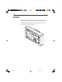
1
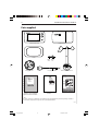
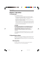
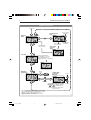
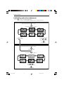
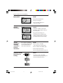
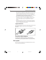
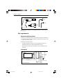
ST40 Wind
Instrument
Owner’s
Handbook
Document number: 81160_3
Date: 1st May 2001
160_3cov.p65
1
01/05/01, 16:14
Copyright © Raymarine Limited 2001
160_3cov.p65
2
01/05/01, 16:14
i
Preface
Important information
WARNING
Although your ST40 instrument is designed to give accurate and
reliable performance, it should serve only as an aid to navigation
and should never lead to the erosion of good seamanship. Always
maintain a permanent watch and be aware of situations as they
develop.
EMC conformance
All Raymarine equipment and accessories are designed to the best
industry standards for use in the leisure marine environment.
The design and manufacture of Raymarine equipment and accessories
conform to the appropriate Electromagnetic Compatibility (EMC)
standards, but correct installation is required to ensure that performance
is not compromised.
Handbook information
To the best of our knowledge, the information in this handbook was
correct when it went to press. However, the Raymarine policy of
continuous product improvement may change product specifications
without notice. Consequently, unavoidable differences may occur
between the product and the handbook from time to time, for which
Raymarine cannot accept liability.
160_3pre.p65
1
01/05/01, 16:14
ii
160_3pre.p65
ST40 Wind Instrument Owner’s Handbook
2
01/05/01, 16:14
iii
Preface
Contents
Important information .......................................................... i
WARNING ......................................................................... i
EMC conformance ............................................................. i
Handbook information ....................................................... i
Preface ..................................................................................... v
Parts supplied ................................................................... vi
Chapter 1: Operation ............................................................. 1
1.1 Introduction ................................................................. 1
1.2 Operating procedures .................................................. 1
Silencing alarms .......................................................... 1
Backlighting and contrast adjustment ......................... 3
1.3 Screen descriptions ..................................................... 4
Apparent and true wind screens .................................. 4
Locked apparent wind screen ...................................... 4
1.4 High wind speed alarm ............................................... 4
Indications ................................................................... 5
True wind ............................................................... 5
Apparent wind ....................................................... 5
Enabling/disabling alarm ............................................. 5
Chapter 2: Maintenance and Fault Finding ........................ 7
2.1 Maintenance ................................................................ 7
Servicing and safety .................................................... 7
Instrument .................................................................... 7
Transducer ................................................................... 8
Cabling ........................................................................ 8
2.2 Fault finding ................................................................ 8
Preliminary procedures ............................................... 8
Fixing faults ................................................................. 8
Assistance .................................................................. 10
160_3pre.p65
3
01/05/01, 16:14
iv
ST40 Wind Instrument Owner’s Handbook
Chapter 3: Installation ......................................................... 11
3.1 Planning your installation ......................................... 11
EMC installation guidelines ...................................... 11
Suppression Ferrites ........................................... 12
Connections to Other Equipment ......................... 12
Tools required ........................................................... 12
Site requirements ....................................................... 13
Rotavecta wind transducer ................................... 13
Instrument ............................................................ 13
3.2 Procedures ................................................................. 14
Fitting Rotavecta transducer ...................................... 14
Running transducer cable .................................... 15
Connections to the instrument ................................... 16
Stand-alone connections ...................................... 17
SeaTalk connections ............................................ 18
Fitting the instrument ................................................. 18
Desktop Mounting Bracket .................................. 20
3.3 Calibration requirement ............................................ 21
Chapter 4: Calibration ......................................................... 23
4.1 Introduction ............................................................... 23
EMC conformance .................................................... 23
4.2 User calibration ......................................................... 23
4.4 Dealer calibration ...................................................... 25
Instrument Specification .................................................... 27
Glossary ................................................................................. 29
Index ...................................................................................... 31
160_3pre.p65
4
01/05/01, 16:14
v
Preface
Preface
Thank you for purchasing a Raymarine product. We are sure your
ST40 instrument will give you many years of trouble-free operation.
This instrument is designed to provide reliable performance, even
under the most demanding conditions.
D48
160_3pre.p65
5
01/05/01, 16:14
08-2
vi
ST40 Wind Instrument Owner’s Handbook
Parts supplied
WIND
ST40
ST40 Wind instrument
Instrument Cover
Gasket
Fixing Thumb
stud
nut
Clamping bracket
1 m (3 ft) power cable
Rotavecta wind transducer
ST40 Wind Instrument - quick reference guide
Normal operation
SWITCH ON
ST40
Wind
Instrument
Owner's
Handbook
Worldwide
Distributors
Locked
apparent
wind
Apparent
wind
Course computer
sets vane lock
Available only if boat
speed information is
present on SeaTalk
Course computer
sets vane lock
True
wind
Auto locked
apparent
wind
Alarm on/off
3 seconds
Only available on master
High
instruments. Times out to the
previous permanent screen wind speed
alarm
after 5 seconds.
Set
alarm
level
Momentary
+
-
With Set alarm level screen displayed,
press the
and
keys simultaneously
to save the alarm level and return to
normal operation.
Adjusting display backlighting/contrast
To enter adjust mode, press
OFF
for 1 second to adjust BACKLIGHTING and a further 1 second to adjust CONTRAST
LEVEL 1
LEVEL 2
To exit adjust mode press
Owner’s Handbook.
Warranty document and fitting
templates included in Handbook
Worldwide Service Centre
Handbook.
LEVEL 3
or
LEVEL 2
LEVEL 1
or wait for 5 second timeout
Quick Reference Guide
Note:
The items shown here are supplied for an ST40 Wind system. If an instrument is purchased separately, a transducer
is not included. If any item is not present, contact your Raymarine Dealer.
D4752-3
160_3pre.p65
6
01/05/01, 16:14
1
Chapter 1: Operation
Chapter 1: Operation
1.1 Introduction
Your ST40 Wind instrument:
• Provides apparent wind speed and direction information. Wind
speed units can be either knots (KTS) or metres per second (M/S), as
set during User calibration (see Chapter 4, Calibration).
• Provides true wind speed and direction information, if boat speed
information is available on SeaTalk.
• Enables a locked apparent wind angle to be defined either manually,
or automatically by a course computer. In this mode, the instrument
shows the deviations from the locked wind angle and the direction to
steer to achieve the locked wind angle.
CAUTION
Your instrument is calibrated to factory (default) settings when
first supplied and must therefore be calibrated before use, to
ensure optimum performance on your vessel. Do NOT use the
instrument until the calibration procedures have been
satisfactorily completed, using the procedures in Chapter 4,
Calibration.
Coloured bezel and Desktop Mounting Bracket options are available
for your ST40 instrument. Contact your Raymarine dealer for further
information.
1.2 Operating procedures
Operating information is presented in flow chart form. The flow charts
show the various operating screens and key presses necessary to carry
out the various instrument functions. Key presses are momentary unless
otherwise stated.
Silencing alarms
To silence an alarm (see the Alarms section, later in this chapter),
momentarily press any one of the instrument keys.
160_3c01.p65
1
01/05/01, 16:14
2
ST40 Wind Instrument Owner’s Handbook
NORMAL OPERATION
Switch on
Locked apparent
wind
Apparent
wind
Increase locked
wind angle
STEER
ST40
ST40
WIND
WIND
Course computer
enters vane lock
Course computer
enters vane lock
Decrease locked
wind angle
Auto locked
apparent
wind
True wind
ST40
WIND
If boat speed information
(from SeaTalk) is not present,
true wind information is not
available and this screen is displayed
CAL
ST40
WIND
High wind
speed alarm
Alarm
on/off
Set high wind
speed alarm
threshold
3 seconds
ST40
WIND
Increase
+
Momentary
ST40
WIND
With Set high wind speed alarm
threshold screen displayed, press the
and
keys simultaneously
to save the alarm level and return to
normal operation.
Note: The High wind speed alarm screen is available
only on master instruments. It is a temporary screen and
will time-out to the previous permanent screen
(Apparent wind or True wind) after 5 seconds.
160_3c01.p65
2
Decrease
D4753-2
01/05/01, 16:15
3
Chapter 1: Operation
Backlighting and contrast adjustment
Hold down
for 1 second to enter Adjust Backlight mode
for 2 seconds to move through Adjust Backlight mode and enter Adjust Contrast mode
ADJUST BACKLIGHTING
During normal operation, press
for 1 second
The current backlighting level is displayed.
Select the required backlighting level then:
to adjust contrast,
press
for 1 second
to return to normal operation,
or
press
or wait for 5 second timeout
Normal operation
ADJUST CONTRAST
During normal operation, press
for 2 seconds
via Adjust Backlighting
The current contrast level is displayed.
Select the required contrast level then
press
or
or wait for 5 second timeout
Normal operation
D4856-1
160_3c01.p65
3
01/05/01, 16:15
4
ST40 Wind Instrument Owner’s Handbook
1.3 Screen descriptions
Apparent and true wind screens
Boat heading
Wind angle
Either A (apparent)
or T (true)
Wind direction with
respect to boat
heading. Either
apparent or true.
Wind speed
Either apparent
or true, as indicated
above.
If apparent wind information is displayed,
press
to apply the current wind
bearing as the locked heading
D4792-2
Locked apparent wind screen
Locked wind
angle
Flashing segment
indicates the
divergence of the
apparent wind from
the locked wind
angle
P = port,
S = starboard.
Relative direction
of the locked wind
angle
STEER
Apparent wind
speed
Direction to steer
indicator to achieve
locked wind angle
Use
or
to change locked wind angle, as required.
Press
to return to the Apparent wind screen
Note:
In auto lock mode, a similar screen is displayed with an A LOCK
annunciator, to indicate that the locked wind angle is controlled
by the course computer and cannot be changed manually.
D4793-2
1.4 High wind speed alarm
The high wind speed alarm threshold is set up at the Set high wind
speed alarm threshold screen and the alarm sounds if the alarm is
switched on and the wind speed exceeds this threshold.
160_3c01.p65
4
01/05/01, 16:15
5
Chapter 1: Operation
Indications
ST40
WIND
D4754-2
True wind
If boat speed information is available at the ST40 Wind instrument
(from a SeaTalk bus), the alarm is triggered if TRUE wind speed
exceeds the threshold.
Apparent wind
If boat speed information is not present, the alarm is triggered if the
APPARENT wind speed exceeds the threshold.
Enabling/disabling alarm
You can enable or disable the high wind speed alarm function (i.e.
switch it on or off ) by selecting the Set high wind speed alarm
threshold screen (see Normal operation) and holding down the
key for 3 seconds (toggle action).
160_3c01.p65
5
01/05/01, 16:15
6
160_3c01.p65
ST40 Wind Instrument Owner’s Handbook
6
01/05/01, 16:15
7
Chapter 2: Maintenance and Fault Finding
Chapter 2: Maintenance and Fault Finding
2.1 Maintenance
Servicing and safety
• Raymarine equipment should be serviced only by authorised
Raymarine service technicians. They will ensure that service
procedures and replacement parts used will not affect performance.
There are no user-serviceable parts in any Raymarine product.
• Some products generate high voltages, so never handle the cables/
connectors when power is being supplied to the equipment.
• When powered up, all electrical equipment produces
electromagnetic fields. These can cause adjacent pieces of electrical
equipment to interact with one another, with a consequent adverse
affect on operation. In order to minimise these effects and enable
you to get the best possible performance from your Raymarine
equipment, guidelines are given in the installation instructions, to
enable you to ensure minimum interaction between different items
of equipment, i.e. ensure optimum Electromagnetic Compatibility
(EMC).
• Always report any EMC-related problem to your nearest Raymarine
dealer. We will use any such information to improve our quality
standards.
• In some installations, it may not be possible to prevent the
equipment from being affected by external influences. In general
this will not damage the equipment but it can lead to spurious
resetting action, or momentarily may result in faulty operation.
• Always switch off the power to Raymarine equipment before
working on it.
When requesting service, please quote equipment Type, Model
Number, Serial Number and, if possible, Software Release Issue. The
Software Release Issue can be ascertained by means of the
Intermediate Calibration facility, see Chapter 4, Calibration.
Instrument
Certain atmospheric conditions may cause a small amount of
condensation to form on the instrument window. This will not harm the
instrument and will clear after the instrument has been switched on for a
short period.
160_3c02.p65
7
01/05/01, 16:15
8
ST40 Wind Instrument Owner’s Handbook
Periodically clean your ST40 instrument with a soft damp cloth. Do
NOT use chemical or abrasive materials to clean the instrument.
Cabling
Examine all cables for chafing or other damage to the outer shield and,
where necessary, replace and re-secure.
2.2 Fault finding
Preliminary procedures
If you appear to have a problem, first check the security of the
connections at the rear of the instrument and reconnect any that are
loose.
Changes in the electronic environment may adversely affect the
operation of your ST40 equipment. Typical examples of such changes
are:
• Electrical equipment has recently been installed or moved aboard
your vessel.
• You are in the vicinity of another vessel or shore station emitting
radio signals.
Fixing faults
All Raymarine products are subjected to comprehensive test and
quality assurance programmes prior to packing and shipping. However,
if a fault occurs, the following guidelines may help to identify and
rectify the problem.
Low battery
Action
Recharge your vessel’s battery as
soon as possible
D4755-2
160_3c02.p65
8
01/05/01, 16:15
9
Chapter 2: Maintenance and Fault Finding
Action
Check fuse/circuit breaker.
Display blank
Check power supply.
ST40
WIND
D4756-2
No wind
information
Action
Check the condition of the wind
transducer cable and the security of
the connections.
ST40
WIND
If apparrent (A) wind speed
information is present but true (T)
wind speed information is not, boat
speed information may be missing.
OR
ST40
SeaTalk
information
not being
transferred
between
instruments
Check SeaTalk cabling and
connector security.
WIND
D4757-2
For example, backlighting
level changes implemented
at one instrument do not
affect other instruments
Action
Check security of SeaTalk
connections between instruments.
Check condition of SeaTalk cables.
Isolate faulty instrument by
disconnecting instruments one by one.
A group of SeaTalk
instruments not
working
Action
ST40
WIND
ST40
WIND
ST40
WIND
Check the security of SeaTalk
connectors between functioning and
non-functioning instruments.
D4758-2
160_3c02.p65
9
01/05/01, 16:15
10
ST40 Wind Instrument Owner’s Handbook
Assistance
If you are unable to rectify any problem, please contact your local
Raymarine Dealer for assistance.
160_3c02.p65
10
01/05/01, 16:15
11
Chapter 3: Installation
Chapter 3: Installation
This chapter describes how to install the ST40 Wind instrument, and
associated Rotavecta wind transducer.
3.1 Planning your installation
Determine the best positions for both transducer and instrument, such
that the EMC installation guidelines and the Site Requirements (below)
are satisfied.
EMC installation guidelines
All Raymarine equipment and accessories are designed to the best
industry standards for use in the leisure marine environment.
Their design and manufacture conform to the appropriate
Electromagnetic Compatibility (EMC) standards, but correct
installation is required to ensure that performance is not compromised.
Although every effort has been taken to ensure that they will perform
under all conditions, it is important to understand what factors could
affect the operation of the product.
The guidelines given here describe the conditions for optimum EMC
performance, but it is recognised that it may not be possible to meet all
of these conditions in all situations. To ensure the best possible
conditions for EMC performance within the constraints imposed by
any location, always ensure the maximum separation possible between
different items of electrical equipment.
For optimum EMC performance, it is recommended that wherever
possible:
• All Raymarine equipment and cables connected to it are:
• At least 1 m (3 feet) from any equipment transmitting or cables
carrying radio signals e.g. VHF radios, cables and antennas. In
the case of SSB radios, the distance should be increased to 2 m
(7 ft).
• More than 2 m (7 ft) from the path of a radar beam. A radar
beam can normally be assumed to spread 20 degrees above and
below the radiating element.
160_3c03 .p65
11
01/05/01, 16:15
12
ST40 Wind Instrument Owner’s Handbook
• The equipment is supplied from a different battery from that used for
engine start. Voltage drops below 10 V in the power supply to our
products, and starter motor transients, can cause the equipment to
reset. This will not damage the equipment, but may cause the loss of
some information and may change the operating mode.
• Raymarine specified cables are used at all times. Cutting and
rejoining these cables can compromise EMC performance and so
must be avoided unless doing so is detailed in the installation
manual.
• If a suppression ferrite is attached to a cable, this ferrite should not
be removed. If the ferrite needs to be removed during installation it
must be reassembled in the same position.
Suppression Ferrites
The following illustration shows typical cable suppression ferrites fitted
to Raymarine equipment. Always use the ferrites supplied by
Raymarine.
D3548-2
Connections to Other Equipment
If your Raymarine equipment is going to be connected to other
equipment using a cable not supplied by Raymarine, a suppression
ferrite MUST always be fitted to the cable close to the Raymarine unit.
Tools required
The tools required for fitting the standard ST40 instrument system are
shown in the following illustration.
160_3c03 .p65
12
01/05/01, 16:15
13
Chapter 3: Installation
4 mm
(5/32 inch)
2.5 mm
(1/10 inch)
57 mm
(2.25 in)
D4643-3
Note: If you intend fitting a nonstandard transducer, extra tools may
be required
Site requirements
Rotavecta wind transducer
The Rotavecta wind transducer can be either mounted on a flat surface
or clamped to a horizontal rail. Suitable rail diameters are from 23 mm
(29/32 inch) to 25 mm (1 inch).
The Rotavecta must be fitted:
• As high as possible and away from any equipment which may
shield the transducer or otherwise disturb the air flow.
• In a position which allows reasonable access for installation and
servicing.
Instrument
55 mm
(2.2 in)
70 mm
(2.8 in)
ST40
30 mm (1.2 in)
minimum cable clearance
126 mm (5.0 in)
Instrument dimensions
160_3c03 .p65
13
21 mm
(0.8 in)
17 mm
(0.67 in)
01/05/01, 16:15
D4644-2
14
ST40 Wind Instrument Owner’s Handbook
CAUTION:
The presence of moisture at the rear of the instrument could cause
damage either by entering the instrument through the breathing
hole or by coming into contact with the electrical connectors.
Each instrument must be positioned where:
• It is easily read by the helmsman or navigator
• It is protected against physical damage
• It is at least 230 mm (9 in) from a compass
• It is at least 500 mm (20 in) from radio receiving equipment
• There is reasonable rear access for installation and servicing
• The rear of the instrument is protected from water.
3.2 Procedures
Adapt these procedures as appropriate, to suit your individual
requirement.
CAUTION:
Where it is necessary to cut holes (e.g. for cable routing and
instrument mounting), ensure that these will not cause a hazard by
weakening critical parts of the vessel’s structure. If in doubt, seek
advice from a reputable boat builder.
Fitting Rotavecta transducer
On flat surface
On rail
Rotavecta mounting options
160_3c03 .p65
14
D4833-1
01/05/01, 16:15
15
Chapter 3: Installation
Clamp screws
Gasket
Rail clamp details
Adaptor
pieces
Grub screw
Clamping methods for
different rail sizes
Rail diameter 23 mm (0.9 inch) or more but
less than 25 mm (1.0 inch), use adaptor pieces
Rail diameter 25 mm (1.0 inch),
do not use adaptor pieces
Using the Rotavecta rail clamp
D4834-1
Running transducer cable
The Rotavecta transducer has a 20 m (65 ft) cable, fitted with spade
terminals at the free end, for connection to the ST40 Wind instrument.
Observing the following guidelines, run the cable to the instrument:
• If the cable has to be fed through the deck, always use a good quality
deck gland.
• Where cables are fed through holes, always use grommets to prevent
chafing.
• Secure long cable runs so they do not present a hazard.
• Wherever possible, route the cable away from fluorescent lights,
engines, radio transmitting equipment, as these may cause
interference.
160_3c03 .p65
15
01/05/01, 16:15
16
ST40 Wind Instrument Owner’s Handbook
Connections to the instrument
You can connect your instrument:
• Directly to the Rotavecta, transducer as a stand-alone master
instrument. When connected in this manner, the instrument must be
connected to a suitable power source using the 1 m (3 ft) power
cable provided.
• As part of a SeaTalk system either as a repeater or, with a wind
transducer also connected as a system master. To connect to
SeaTalk, you will need an additional SeaTalk Interconnection Kit
(Part No. E25028). When connected in this manner, power can be
provided from the SeaTalk bus (e.g. from the autopilot).
You can also connect the instrument to both the Rotavecta transducer
and SeaTalk. When thus connected, the instrument will be the master
wind instrument for the SeaTalk system.
If it is necessary to fit spade connectors to the transducer cable, do so as
shown in the following illustration. Prepare the cable, as at (a), and fit
the spade connectors, as at (b). When fitting each spade connector,
ensure that wire strands do not extend beyond the rear of the spade
connector insulation.
10 mm
50 mm
(a)
4 mm
(b)
3 mm
Preparing wires for connection
160_3c03 .p65
16
D4467-3
01/05/01, 16:15
17
Chapter 3: Installation
Stand-alone connections
CAUTION
Ensure that the power supply for each stand-alone ST40
instrument is protected by a 3 A fuse or circuit breaker.
3 A circuit breaker
Red +ve
Note:
A 3 A fuse can be used in place of
the circuit breaker, if preferred.
Uninsulated wire (screen) -ve
12 V dc supply
(e.g. battery)
Power cable
_
+
Cable from
wind transducer
Red
Blue
Connections to a stand-alone instrument
160_3c03 .p65
17
D4794-2
01/05/01, 16:15
18
ST40 Wind Instrument Owner’s Handbook
SeaTalk connections
CAUTION
When instruments are connected to SeaTalk, ensure that the
power supply for the SeaTalk 12 V line is protected by a 5 A fuse
or circuit breaker.
Note:
A 5 A fuse can be used in place of
the circuit breaker, if preferred.
5 A circuit breaker
Red (+ve)
12 V dc supply
(e.g. course
computer
or battery)
Uninsulated wire
(screen) -ve
Power cable
SeaTalk bus
SeaTalk bus
SeaTalk interface
kit
Typical SeaTalk connections
D4826-2
Fitting the instrument
Fit your ST40 instrument as shown in the following illustrations.
1
Remove template from handbook (immediately after index), apply to required location
and mark cutting centre.
ST4
0 In
stru
me
nt T
em
pla
te
TOP
sha Cut
ded out
are
ao
nly
Cutting centre
Cut
57 out h
diamm (2ole
me .25
ter in
)
D4759-1
160_3c03 .p65
18
01/05/01, 16:15
19
Chapter 3: Installation
2
Cut hole
57 mm (2.25 in) cutter
D4760-1
3
Peel protective sheets from gasket
D4770-1
4
Stick gasket to rear of instrument
D4761-1
160_3c03 .p65
19
01/05/01, 16:16
20
ST40 Wind Instrument Owner’s Handbook
5
Screw stud into instrument
D4819-1
6
Feed cables through clamping bracket,
connect cables then secure instrument with
bracket and thumb nut
D4818-1
Desktop Mounting Bracket
An optional Desktop Mounting Bracket (Part No. E25024) enables you
to mount your ST40 instrument in locations where other forms of
mounting are impractical.
160_3c03 .p65
20
01/05/01, 16:16
21
Chapter 3: Installation
D4646-1
To bracket mount your ST40 instrument, do so in accordance with the
Instruction Sheet, which is included with the Desktop Mounting
Bracket.
3.3 Calibration requirement
Once installation is complete and before you use your instrument, carry
out the calibration procedures detailed in Chapter 4, Calibration.
160_3c03 .p65
21
01/05/01, 16:16
22
160_3c03 .p65
ST40 Wind Instrument Owner’s Handbook
22
01/05/01, 16:16
23
Chapter 4: Calibration
Chapter 4: Calibration
4.1 Introduction
The procedures in this Chapter must be carried out before the
equipment is used operationally, to optimise the performance of the
instrument with the vessel.
Calibration information is presented in flow chart form. The flow charts
show the various calibration screens and key presses necessary to carry
out calibration. All key presses are momentary unless otherwise stated.
EMC conformance
• Always check the installation before going to sea to make sure that it
is not affected by radio transmissions, engine starting etc.
4.2 User calibration
User calibration enables you to:
• Set the wind angle and speed response values. Use higher response
values for rapid updates in reasonable weather conditions (for
example, when you are trying to maintain a locked course). Use
lower response values in squally conditions to damp out unstable
readings.
• Set the required wind speed units, either KTS (knots) or M/S (metres
per second).
• Linearise and align the wind transducer.
Power up the instrument then follow the procedure in the User
calibration flow diagram.
160_3c04.p65
23
01/05/01, 16:16
24
ST40 Wind Instrument Owner’s Handbook
USER CALIBRATION
During normal operation
hold down
and
for approximately 2 seconds
Entry
screen
ST40
WIND
Note:
If there is no key
activity when the
Entry screen is
displayed, calibration
will time out to
normal operation
after 5 seconds,
Align
transducer
CAL
ST40
15 (fast)
Set wind angle
response
Increase value
WIND
Decrease value
CAL
ST40
When linearisation successful
WIND
1 (slow)
(1 second)
15 (fast)
Set wind speed
response CAL
ST40
Linearise
transducer
WIND
CAL
1 (slow)
Set wind speed
units
2 turns
minimum
ST40
CAL
Repeater
ST40
Bypass
linearisation
Start
linearisation
WIND
Master
WIND
M/S
If the wind speed is outside of
the range suitable for transducer
linearisation, the legend
is displayed on the Linearise
transducer screen.
To save your settings and return to normal operation from any screen,
hold down
and
for approximately 2 seconds
D4764-2
160_3c04.p65
24
01/05/01, 16:16
25
Chapter 4: Calibration
4.3 Intermediate calibration
Intermediate calibration enables you to:
• Check the instrument software version.
• Check the instrument status - either master (shown as RPTR NO) or
repeater (shown as RPTR YES). You cannot change this.
Follow the procedure in the Intermediate calibration flow diagram.
INTERMEDIATE CALIBRATION
During normal operation
hold down
and
for approximately 4 seconds
Software
version
ST40
Note:
If there is no key activity when
the Software version screen
is displayed, calibration will
time out to normal operation
after 5 seconds
WIND
Instrument
status
CAL
ST40
WIND
To return to normal operation from either screen,
hold down
and
for approximately 2 seconds
D4765-2
4.4 Dealer calibration
Dealer calibration enables you to set:
• User calibration on/off.
• Boat show mode on/off.
Dealer calibration also gives access to the Factory defaults screen.
This enables you to reapply the factory settings if you want to reset the
instrument to a known operating condition.
Follow the procedure in the Dealer calibration flow diagram.
160_3c04.p65
25
01/05/01, 16:16
26
ST40 Wind Instrument Owner’s Handbook
DEALER CALIBRATION
Hold down
and
for approximately 12 seconds
Entry
screen
Note:
If there is no key activity when the Entry screen
is displayed, calibration will time out to normal
operation after 5 seconds,
WIND
ST40
Calibration
access
CAL
ST40
WIND
If
If
Return to normal
operation with factory
defaults applied
Factory
defaults
Boat show
mode
CAL
CAL
ST40
ST40
WIND
WIND
CAUTION:
Do NOT switch the Boat Show mode on.
This function must only be used for
demonstration purposes.
To save your settings and return to normal operation from any screen,
hold down
and
for approximately 2 seconds
D4766-2
160_3c04.p65
26
01/05/01, 16:16
Instrument Specification
27
Instrument Specification
Supply voltage:
10 V dc to 16 V dc.
Current consumption (12 V supply):
25 mA typical.
60 mA with maximum backlighting.
Operating temperature:
0°C to +70°C.
Interfaces:
SeaTalk.
Overall dimensions:
126 mm x 70 mm x 38 mm
(5.00 inches x 2.80 inches x 1.55 inches).
Boss diameter:
55 mm (2.20 inches).
Wind speed range:
0 to 60 knots.
High true wind speed alarm:
5 knots to 50 knots.
Wind angle
180° port to 180° starboard.
Approvals:
CE - conforms to
89/336/EC(EMC), EN60945.
160_3spe.p65
27
01/05/01, 16:16
28
160_3spe.p65
ST40 Wind Instrument Owner’s Handbook
28
01/05/01, 16:16
Glossary
29
Glossary
EMC
Electromagnetic compatibility.
KTS
Knots.
M
Metres.
M/S
Metres per second.
Response
The rate at which an instrument responds to changes in wind speed and
direction. Values are from 1 (slow response) to 15 (fast response).
SeaTalk
SeaTalk is a proprietary Raymarine system which links different
compatible products, to provide a single, integrated navigational system.
SeaTalk can also communicate with non-SeaTalk equipment using the
internationally- accepted National Marine Electronics Association
(NMEA) protocol. Contact your Raymarine dealer for details.
160_3glo.p65
29
01/05/01, 16:16
30
160_3glo.p65
ST40 Wind Instrument Owner’s Handbook
30
01/05/01, 16:16
31
Index
Index
A
F
Alarm
enable/disable 5
indications 5
range 27
setting level 2
silencing 1
Align transducer 24
Apparent wind speed 2
Apparent/true wind screen
Factory defaults 25
Fault finding 8
assistance 10
blank display 9
low battery 8
no wind information 9
SeaTalk problems 9
4
High wind speed alarm
enable/disable 5
indications 5
setting level 2
B
Backlighting 3
Boat show mode
H
25
4
C
I
Calibration 23–26
Dealer 25–26
Intermediate 25
setting user access 26
User 23–24
Calibration requirement 1, 21
Cleaning the instrument 8
Condensation 7
Connecting the instrument 16–18
Contrast 3
Current consumption 27
Installation 11–21
connecting the instrument 16–18
fitting the instrument 18–21
planning 11–14
Rotavecta wind transducer 14–15
site requirements 13–14
tools required 12–13
Instrument
cleaning 8
condensation 7
connecting 16–18
current consumption 27
dimensions 27
fitting 18–21
site requirements 13–14
status (master or repeater) 25
supply voltage 27
Intermediate calibration 25
D
Dealer calibration 25–26
Desktop Mounting Bracket
Dimensions 27
20–21
E
EMC
conformance i, 23
installation guidelines
160_3ind.p65
11–12
31
01/05/01, 16:16
32
ST40 Wind Instrument Owner’s Handbook
L
Linearising transducer 24
Locked apparent wind screen
Locked wind angle
auto lock 2
manual setting 2
Low battery indication 8
4
Silencing alarm 1
Site requirements 13–14
instrument 13–14
transducer 13
Software version 25
Specifications 27
M
T
Maintenance 7–8
Transducer
aligning 24
fitting 14–15
linearising 24
site requirements 13
True wind speed 2
N
Normal operation
2–3
O
Operating temperature
Operation 1–5
27
User calibration
P
Parts supplied
Voltage
R
27
W
13
S
Servicing and safety 7
Setting
backlighting 3
contrast 3
high wind alarm level 2
wind angle response 24
wind speed response 24
wind speed units 24
160_3ind.p65
23–24
V
vi
Rotavecta
fitting 14–15
site requirements
U
32
Wind angle
appropriate response values
range 27
set response 24
Wind speed
appropriate response values
range 27
set response 24
set units 24
01/05/01, 16:16
23
23
160_3tem.p65
33
01/05/01, 16:16
ST40 Instrument Template
Cut out
shaded area only
TOP
D4800-1
Cut out hole
57 mm (2.25 in)
diameter
160_3tem.p65
34
01/05/01, 16:16
84064_8.fm Page 1 Monday, April 9, 2001 4:42 PM
Limited Warranty Certificate
Raymarine warrants each new Light Marine/Dealer Distributor Product to be of good materials and
workmanship, and will repair or exchange any parts proven to be defective in material and
workmanship under normal use for a period of 2 years/24 months from date of sale to end user, except
as provided below.
Defects will be corrected by Raymarine or an authorized Raymarine dealer. Raymarine will, except
as provided below, accept labor cost for a period of 2 years/24 months from the date of sale to end user.
During this period, except for certain products, travel costs (auto mileage and tolls) up to 100 round
trip highway miles (160 kilometres) and travel time of 2 hours, will be assumed by Raymarine only
on products where proof of installation or commission by authorized service agents, can be shown.
Warranty Limitations
Raymarine Warranty policy does not apply to equipment which has been subjected to accident, abuse
or misuse, shipping damage, alterations, corrosion, incorrect and/or non-authorized service, or
equipment on which the serial number has been altered, mutilated or removed.
Except where Raymarine or its authorized dealer has performed the installation, it assumes no
responsibility for damage incurred during installation.
This Warranty does not cover routine system checkouts or alignment/calibration, unless required by
replacement of part(s) in the area being aligned.
A suitable proof of purchase, showing date, place, and serial number must be made available to
Raymarine or authorized service agent at the time of request for Warranty service.
Consumable items, (such as: Chart paper, lamps, fuses, batteries, styli, stylus/drive belts, radar mixer
crystals/diodes, snap-in impeller carriers, impellers, impeller bearings, and impeller shaft) are
specifically excluded from this Warranty.
Magnetrons, Cathode Ray Tubes (CRT), TFT Liquid Crystal Displays (LCD) and cold cathode
fluorescent lamps (CCFL), hailer horns and transducers are warranted for 1 year/12 months from date
of sale. These items must be returned to a Raymarine facility.
All costs associated with transducer replacement, other than the cost of the transducer itself, are
specifically excluded from this Warranty.
Overtime premium labor portion of services outside of normal working hours is not covered by this
Warranty.
Travel cost allowance on certain products with a suggested retail price below $2500.00 is not
authorized. When/or if repairs are necessary, these products must be forwarded to a Raymarine
facility or an authorized dealer at owner’s expense will be returned via surface carrier at no cost to the
owner.
Travel costs other than auto mileage, tolls and two (2) hours travel time, are specifically excluded on
all products. Travel costs which are excluded from the coverage of this Warranty include but are not
limited to: taxi, launch fees, aircraft rental, subsistence, customs, shipping and communication
charges etc. Travel costs, mileage and time, in excess to that allowed must have prior approval in
writing.
TO THE EXTENT CONSISTENT WITH STATE AND FEDERAL LAW:
(1) THIS WARRANTY IS STRICTLY LIMITED TO THE TERMS INDICATED HEREIN, AND
NO OTHER WARRANTIES OR REMEDIES SHALL BE BINDING ON RAYMARINE
INCLUDING WITHOUT LIMITATION ANY WARRANTIES OF MERCHANTABLE OR
FITNESS FOR A PARTICULAR PURPOSE.
(2) Raymarine shall not be liable for any incidental, consequential or special (including punitive or
multiple) damages.
All Raymarine products sold or provided hereunder are merely aids to navigation. It is the
responsibility of the user to exercise discretion and proper navigational skill independent of any
Raymarine equipment.
Document number: 84064-8
April 2001
84064_8.fm Page 2 Monday, April 9, 2001 4:42 PM
Factory Service Centers
United States of America
UK, Europe, Middle East, Far East
Raymarine Inc
22 Cotton Road, Unit D
Nashua, NH 03063-4219, USA
Raymarine Ltd
Anchorage Park, Portsmouth
PO3 5TD, England
Telephone: +1 603 881 5200
Fax: +1 603 864 4756
www.raymarine.com
Telephone: +44 (0)23 9269 3611
Fax: +44 (0)23 9269 4642
www.raymarine.com
Sales & Order Services
Telephone: +1 800 539 5539 Ext. 2333 or
+1 603 881 5200 Ext. 2333
Customer Support
Telephone: +44 (0)23 9271 4713
Fax: +44 (0)23 9266 1228
Technical Support
Telephone: +1 800 539 5539 Ext. 2444 or
+1 603 881 5200 Ext. 2444
Email: [email protected]
Email: [email protected]
Product Repair Center
Telephone: +1 800 539 5539 Ext. 2118
Stick barcode label here
Purchased from
Purchase date
Dealer address
Installed by
Installation date
Commissioned by
Commissioning date
Owner’s name
Mailing address
This portion should be completed and retained by the owner.