1
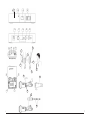
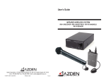
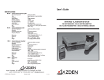
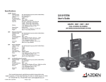
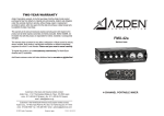
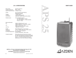
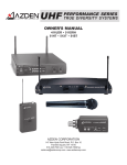
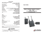
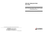
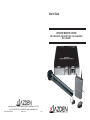
User’s Guide
INFRARED WIRELESS SYSTEM
IRR-10 RECEIVER - IRB-10 BODY-PACK - IRH-10 HANDHELD
IRD-10 SENSOR
Azden Corporation, 147 New Hyde Park Road, Franklin Square, NY 11010
vox - 516.328.7500 • fax - 516.328.7506 • email - [email protected]
© 2000 Azden Corporation
Printed in USA
P1014-01
C
B
G
M
N
A
F
H
D
E
E
3
P
O
1
3
IRB-10 (Top View)
5
2
6
4
R
Q
S
T
U
W
V
X
Y
i
7
TABLE OF CONTENTS
EXPLODED VIEWS .................................................................................................................. i
INTRODUCTION ...................................................................................................................... ii
RECEIVER SETUP .................................................................................................................. 1
Receiver front panel ................................................................................................................. 1
Receiver rear panel .................................................................................................................. 1
Mounting the receiver ............................................................................................................... 1
Powering the receiver ............................................................................................................... 1
THE IRB-10 BODY-PACK ....................................................................................................... 1
Batteries for the IRB-10 ............................................................................................................ 1
Frequency selection ................................................................................................................. 2
Power mode selection .............................................................................................................. 2
Adjusting MIC gain ................................................................................................................... 2
Using the IRB-10 ...................................................................................................................... 2
Attaching and using the lanyard with the IRE-10 emitter .......................................................... 3
THE IRH-10 HANDHELD MIC ................................................................................................. 3
Batteries for the IRH-10 ............................................................................................................ 3
Frequency selection ................................................................................................................. 3
Using the IRH-10 ...................................................................................................................... 4
THE IRD-10 EXTERNAL SENSOR .......................................................................................... 4
Mounting bracket instruction .................................................................................................... 4
TROUBLESHOOTING ............................................................................................................. 5
SPECIFICATIONS ................................................................................................................... 6
TROUBLESHOOTING
The single most important thing to ALWAYS check when trouble arises are the batteries.
Make sure they are fresh and the POWER LED is glowing brightly.
SYMPTOM
No POWER LED
CAUSE
a. Receiver switch Is set to “OFF” - change to “ON”
b. External 12VAC power source is not connected or is malfunctioning
c. Dead or very weak battery in body-pack or handheld
No audio from body-pack
a. Make sure the volume on the receiver is turned up for the
appropriate channel and the body-pack is powered ON
b. If two body-packs are being used, make sure they are set to
different frequency channels
c. If using an external mic, make sure it is plugged in to the
body-pack properly and the internal gain control has been
adjusted.
No audio from handheld mic a. Make sure the volume on the receiver is turned up for the
appropriate channel and the handheld mic is powered ON
b. If two handheld mics are being used, make sure they are set
to different frequency channels
Intermittent audio
a. Make sure there is a clear path between the emitter and the
receiving sensor. Best results are obtained when the receiving sensors are mounted high - above everyone’s head
Limited working range
a. Install extra external sensors
b. If using a body-pack, set the Power Mode to Hi
MICROPHONE SUGGESTIONS
In addition to the IRE-10 emitter’s built-in uni-directional microphone, any one of many fine
external microphones can be used. In the case of head or collar worn mics is that it would be
possible to increase the gain (volume) without adding feedback noise. This is due to the
proximity of the mic element to the speaker’s mouth. Any of the following Azden microphones will produce excellent results.
• EX-503 Omni-directional Lavalier
• EX-505U Uni-directional Lavalier
• HS-12 Uni-directional Headset
• HS-9 Omni-directional Headset
• CM-20 Collar-worn
iii
5
II. Frequency Selection:
The IRB-10 can be set to transmit on either one of two preset frequencies. This is so
that two different speakers can talk at the same time in the same room. While it does
not matter which frequency is chosen for the body-pack, two transmitters cannot share
the same frequency at the same time. To select the desired frequency (channel) slide
the switch (T) as shown on the sticker on the back of the battery door.
II. Power Mode Selection:
The IRB-10 has two Power Modes - Lo and Hi. These modes can be selected via a
switch (Q) inside the battery compartment, and affect two areas related to performance - battery life and area coverage. If the body-pack is switched to the Hi position
(Q - to the right) the range is set to maximum (approximately 1600 square feet) while
the battery life is reduced to approximately 10 hours with Alkaline batteries. If, on the
other hand, the body-pack is switched to Lo the operating range is reduced to approximately 1200 square feet and the battery life increases to approximately 15 hours with
Alkaline batteries. Experimentation is the only way to know which position is best for
your room. We suggest, however, that it always best to use the Lo position if possible
as that provides the most economical use.
III. Adjusting MIC Gain:
The MIC gain (volume) is adjustable to compensate for various microphone element
characteristics. The adjustment (R) is located in the battery compartment and can be
adjusted using the provided tool. While speaking into your microphone, adjust the gain
(more gain-clockwise rotation, less gain-counterclockwise rotation) until the desired
volume level is achieved. Best results are normally achieved when the gain control on
the IRB-10 body-pack and the volume control on the IRR-20 receiver (D or F) are both
at their mid-points.
IV. Using the IRB-10:
After inserting fresh batteries, the IRB-10 can be powered by sliding the ON/OFF
Switch (N) to the ON position. The Power LED (O) will glow when the IRB-10 is powered ON as will the red LED on the front panel of the IRR-20 which corresponds to the
chosen channel. Be sure to slide the Power Switch to OFF when not in use to preserve
battery life. The Power LED on the mic will turn from green to red to indicate “Low
Battery”.
2
The emitter (1) must be plugged into the IRB-10 (P) and either attached to the clothing
with the clip (2) or worn around the neck with the lanyard (7) as described in section V.
The emitter acts as the transmitter and, for best results, should be worn in such a way
as to have a clear path to the receiving sensor(s).
IV. Using the IRB-10 (continued):
While there is a built-in microphone in the emitter, for best results an external microphone should be used. This microphone can be attached to the IRB-10 through the
3.5mm EXT. MIC jack (M). See page 5 for microphone suggestions. The internal microphone is disabled when an external mic is attached.
The IRB-10 can be attached to the belt or other clothing by way of the metal belt clip.
It is suggested that the body-pack be worn in the front portion of the body to avoid the
possibility of damaging it.
V. Attaching and Using the Lanyard with the IRE-10 Emitter:
As described above, the emitter can be attached to clothing using the built-in clip (2).
If that is not convenient, or if the built-in auxiliary mic is being used, it is best to use the
included lanyard. To attach, insert the metal clip (2) through the holes (3) on the lanyard’s
clear plastic slide (5).
To adjust the emitter, hold the end of the lanyard (4) and slide the emitter up or down
to the desired position. When using the built-in auxiliary mic it is best to slide the
emitter up as far as possible so that it is close to the mouth (6).
THE IRH-10 HANDHELD MIC (see illustration on page i)
I. Batteries for the IRH-10:
The IRH-10 uses two “AA” batteries or one AN-2A Ni-Cd for power. Batteries are
placed in the battery compartment after unscrewing and removing the bottom portion
of the mic handle (W). When using the AN-2A battery (U) carefully place a FULLY
CHARGED battery in the compartment in the direction shown in the illustration (- to the
top, + to the bottom). OBSERVE PROPER POLARITY! The IRH-10 can also use
either 2 “AA” size Alkaline, Ni-Cd or Ni-MH batteries. When using this size battery, first
place the two batteries (Y) into the included adapter sleeve (X) and then place in the
compartment as shown. Again, OBSERVE PROPER POLARITY! Be sure to use
FRESH “AA” Alkaline batteries, or, in the case of “AA” rechargeable batteries, be sure
that they are FULLY CHARGED before use. Battery life depends on (1) the type of
battery used, (2) the power mode chosen and other factors.
II. Frequency Selection:
The IRH-10 can be set to transmit on either one of two preset frequencies. This is so
that two different speakers can talk at the same time in the same room. While it does
not matter which frequency is chosen for the handheld mic, two transmitters cannot
share the same frequency at the same time. To select the desired frequency (channel)
slide the switch (V) as shown on the sticker on the side of the battery compartment.
3
THE IRH-10 HANDHELD MIC (continued )
RECEIVER SETUP (see illustration on page i)
I. Using the IRH-10:
After installing fresh batteries and choosing a frequency, simply turn the mic/transmitter on by sliding the ON/OFF switch up. The Power LED above the switch will glow as
will the red LED on the front panel of the IRR-20 which corresponds to the chosen
channel. Be sure to slide the Power Switch to OFF when not in use to preserve battery
life. The Power LED on the mic will turn from green to red to indicate “Low Battery”.
I. Receiver Front Panel:
A. Power Switch - turns the receiver On and Off.
B. Power LED - indicates the power state of the receiver.
C. Receiving Sensor - internal receiving infrared sensor.
D. Volume - adjusts the output volume
Best performance is achieved when the mic is held close to the mouth and one speaks
in a normal tone. The mic is designed to be held in the middle of the handle with the
ON/OFF switch facing you. This allows the emitters at the base and near the mic
element to operate at their peak.
THE IRD-10 EXTERNAL SENSOR
To increase the working range of the system, up to three external sensors can be
added. IRD-10 sensors are powered by the receiver and can be plugged into the “EXT.
SENSOR INPUTS” (H and I) on the rear panel. Plugging into inputs 1 and/or 2 (I) adds
to the built-in front sensor (C) and extends the working range by 33 feet in any direction. Plugging into input 3 (H) automatically disconnects the front panel sensor. This
way, if the front panel sensor is blocked (perhaps in a secured cabinet or closet) it can
be replaced. Follow the illustrations below to install the IRD-10 mounting plate and
sensor.
Bend here
II. Receiver Rear Panel:
E. 2-External Sensor Inputs (RCA connector) - Plugging external sensors in here
extends the receiver’s potential working distance.
F. Output Jack - connects the receiver to a mixer or audio amplifier/speaker combination (1/4 inch connector).
G. Power Input - plug in AC-AC adapter (BC-28i) to power receiver (12VAC-1.6A)
H. Channel indicator and serial number.
III. Mounting the Receiver:
As infrared operates “line-of-sight” and can be interrupted by any solid object, it is
strongly suggested that the receiver (or external sensors) be mounted or placed in a
location that puts the receiving sensors above the audience’s heads or any other obstacles.
IV. Powering the Receiver:
The IRR-10 is powered by a BC-28i AC-AC power supply. Before turning the receiver
ON be sure to plug it into an active 110-120VAC wall socket and into the rear of the
IRR-10 (G). DO NOT USE any power supply except the BC-28i.
THE IRB-10 BODY-PACK (see illustration on page i)
Hold bracket in
place and bend
up to 90o
4
1st
Mounting holes
Slide IRD-10
on bracket
Mount with
2 screws
2nd
3rd
Bend up to
desired angle
4th
I. Batteries for the IRB-10:
The IRB-10 uses two “AA” batteries for power. They are placed in the battery compartment (S). After sliding the battery compartment door off, carefully place FRESH batteries in the compartment in the directions shown on the sticker. OBSERVE PROPER
POLARITY! The IRB-10 can use either Alkaline, Ni-Cd or Ni-MH batteries. In the case
of rechargeable batteries, be sure that they are FULLY CHARGED before use. Battery
life depends on (1) the type of battery used, (2) the power mode chosen and other
factors.
1
SPECIFICATIONS
System overall
Working range.............................................IRB-10 – 1600 ft2 w/built-in sensor
IRH-10 – 2500 ft2 w/built-in sensor
Frequency response ...................................50Hz – 9kHz (±3dB) body pack (mic dependent)
50Hz – 5kHz (±3dB) auxiliary emitter mic
40Hz – 9kHz (±3dB) handheld
Dynamic range............................................>100dB
Operating temperature range .....................32o ~ 113oF (0o ~ 45oC)
Noise reduction ...........................................2:1 log compander
IRR-10 1-channel receiver
Sub-carrier frequencies ..............................2.06MHz or 2.56MHz
Type ............................................................super heterodyne – crystal controlled
Modulation...................................................FM
Signal-to-Noise ...........................................>90dB
Image rejection ...........................................>40dB
Reception sensitivity ...................................>25dBμV
Reception selectivity ...................................±40kHz
Audio output adjustment.............................line:+4dB max
Audio output impedance.............................line:<1k ohms
Power requirement......................................12VAC @ 1.6A
Size .............................................................5.55" W x 5.1" D x 0.95" H (141 x 129.5 x 24mm)
Weight .........................................................11oz (311g)
IRB-10 – 2-channel body pack transmitter
Sub-carrier frequencies ..............................2.06MHz & 2.56MHz switchable
Modulation...................................................FM
Audio distortion ...........................................< 1.0% (±40kHz deviation @ 1kHz)
Mic input impedance...................................2.2k ohms
Mic input jack ..............................................3.5mm
Built-in auxiliary mic ....................................uni-directional electret
Mic gain adjustment....................................Max to –50dB
Battery type.................................................2-“AA” alkaline (2 x 1.5V)
2-“AA” rechargeable Ni-MH or Ni-Cd (2 x 1.2V)
Battery life (100mA drain) ......................> 15 hours w/alkaline batteries – low power mode
(160mA drain) ......................> 10 hours w/alkaline batteries – high power mode
Size .............................................................3.94" H x 2.52" W x 1.06" D (100 x 64 x 27mm)
Weight .........................................................4.65oz (132g) – transmitter (w/alkaline batteries)
1.34oz (38g) – clip-on emitter
INTRODUCTION
Thank you for selecting the Azden “RED” infrared system as your wireless solution. We are
confident that it will perform beyond your expectations. For over 40 years Azden Corporation has been creating technologically advanced products. By taking advantage of the latest
in CAD design and SMT production techniques, Azden’s engineers are able to produce
products that exceed the published specifications and perform well beyond the warranty
period.
Azden “RED” represents a breakthrough in wireless. Instead of the normal radio waves that
other wireless systems use, Azden “RED” uses invisible light beams in the infrared range.
Through the use of infrared you will no longer be plagued by outside interference. “RED’s”
enhanced performance assures you of the finest in audio clarity and reliability. The specially
selected high-frequencies provide you with trouble free performance, even in fluorescently
lit rooms. Like all infrared, Azden “RED” will not operate correctly outside in the sunlight.
In the real world, the ability to use multiple systems in the same location without frequency
interference will prove to be a tremendous benefit to you. Using infrared means that the
audio generated in your room stays in your room. Your discussions cannot be overheard on
other systems in other rooms.
Designed by professionals - for professionals, Azden “RED” will provide you with years of
worry-free, high-quality performance.
IRH-10 – 2-channel handheld transmitter
Sub-carrier frequencies ..............................2.06MHz & 2.56MHz switchable
Modulation...................................................FM
Audio distortion ...........................................< 1.0% (±15kHz deviation @ 1kHz)
Microphone element type ...........................uni-directional dynamic
Battery type.................................................2-“AA” alkaline (2 x 1.5V)
2-“AA” rechargeable Ni-MH or Ni-Cd (2 x 1.2V)
1- Azden AN-2A rechargeable Ni-Cd
Battery life (260mA drain)...........................> 10 hours w/alkaline batteries
Size .............................................................10.04" x 2.28" (255 x 58mm)
Weight .........................................................9.1oz (258g) w/alkaline batteries)
IRD-10 external sensor
Cable length................................................32.8' (10m)
Power ..........................................................powered by receiver
Size .............................................................2" W x 3" W x 1" H (50.8 x 76.2 x 25.4mm)
Weight .........................................................4oz (113.4g)
Mounting
included metal bracket
6
Due to constant improvements, specifiations are subject to change without notice.
ii