1
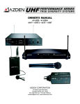
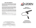
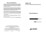
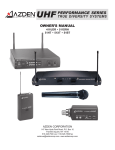
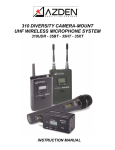
FMX-32
INSTRUCTIONS
Azden Corporation
147 New Hyde Park Road
P.O. Box 10
Franklin Square, NY 11010
vox 516.328.7500 • fax 516.328.7506
[email protected] • www.azdencorp.com
3-CHANNEL PORTABLE MIXER
12
13
FMX-32 SPECIFICATIONS
14
Frequency Response
Main and Unbalanced Output .................... 40-17,000Hz (– 3dB)
Monitor Output ............................................ 50-17,000Hz (– 3dB)
16 15
16
Noise Level
Left & Right Channel .................................. – 114dBu (A weighted, Input Equivalent Level)
17
2
1
T.H.D. ............................................................ >0.05% @ 1KHz (+10dBu output)
8
9
3
10
4
11
5
Balanced Output Level
Electronic Balanced .................................... +0dBu (100K Ω load)
.................................... –6.5dBu (600 Ω load)
6
Unbalanced Output Level
3.5mm Stereo .............................................. – 50dBu (100K Ω load)
7
19
20
18
Monitor Output Level
.25 inch Stereo ............................................ – 4dBu (32 Ω load)
(Recommended Load 16 Ω - 100 Ω)
Maximum Output Level
Balanced Output ......................................... +14dBu (100K Ω load)
......................................... +6.5dBu (600 Ω load)
Unbalanced Output ..................................... –36dBu (100K Ω load)
21
23
22
MIC Input Level
Electronic Balanced .................................... – 50dBu
B
Battery Type/Duration
6-”AA” Alkaline ........................................... approx. 15 hours
Current Drain ............................................... 47mA nominal (Phantom Power OFF)
............................................... 100mA maximum (Phantom Power ON)
A
Phantom Power voltage ............................ 48VDC (+/- 4VDC)
Size ............................................................... 50H x 170W x 110D mm
1.96 x 6.69 x 4.33 inches
Weight without Battery ............................... 27.9 ounces
791 grams
Thank you for purchasing the Azden FMX-32 portable mixer. The FMX-32 has many unique
features, so please read this manual completely before using the mixer. Designed to work
with most microphones that have a low-impedance XLR output, the FMX-32 can be connected to any video camera or audio recorder, which has XLR, or mini-jack mic/line inputs.
LOADING THE BATTERIES: Make sure the mixer is turned OFF. Remove the battery
cover (A) by pressing in the clip, then lift up and remove the cover from the unit. Install 6 new
“AA” ALKALINE batteries into the battery compartment. Be sure to follow the polarity
diagram inside the battery compartment. Do not force the batteries into the compartment.
Replace the battery door (A). New batteries should last up to 15 hours.
MOUNTING OPTIONS:
1) Hook and Loop fastener (supplied): Hook and Loop fastener can be attached to either side
of the mixer and to any adjoining flat surface (camera body, tripod, etc.) The strip with the soft
surface should be attached to the mixer and the strip with the rough surface should be attached
to the adjoining surface.
2) Strap (not supplied): A strap can be looped through the strap cutouts (B) on the sides of the
mixer.
CONTROLS and INPUTS/OUTPUTS
1 through 16
POWER SWITCH (1) and POWER LED (2):
To power the FMX-32 by the internal batteries. Move the POWER switch (1) to INT position.
The POWER ON LED (2) will turn green. When the battery voltage level is low the POWER
ON LED (2) will turn to RED. When the POWER ON LED (2) turns to red replace the
batteries with new “AA” ALKALINE batteries. (See LOADING THE BATTERY above).
When not in use turn the mixer OFF to conserve battery life.
Powering the FMX-32 with an external power supply. (Note: The FMX-32 does not come
with an external power supply. An optional power supply part number BC-26U is available
from the Azden web site www.azdencorp.com.) Move the power switch (1) to EXT position.
The POWER ON LED (2) will turn green. When not in use turn the mixer OFF and disconnect
the power supply from the mixer.
INPUT LEVEL CONTROLS for Channel 1 (3), Channel 2 (4) and Channel 3 (5):
CH1 (3): Controls the input level (volume) of the microphone connected to Input CH 1 (12).
Zero is the lowest (quietest) setting, 10 is the highest (loudest). For the best possible sound and
lowest noise increase the input level control until the input LED lights occasionally.
CH2 (4): Controls the input level (volume) of the microphone connected to Input CH 2 (13).
Zero is the lowest (quietest) setting, 10 is the highest (loudest).For the best possible sound and
lowest noise increase the input level control until the input LED lights occasionally.
CH3 (5): Controls the input level (volume) of the microphone connected to Input CH 3 (14).
Zero is the lowest (quietest) setting, 10 is the highest (loudest).For the best possible sound and
lowest noise increase the input level control until the input LED lights occasionally.
OUTPUT LEVEL LED INDICATORS (7)
For the best sound increase the INPUT LEVEL of CH1, and/or CH2 and/or CH3, so that
the corresponding PEAK LED indicator flashes red occasionally during the loudest parts of
what you are recording. If the indicator does not light it means that the input (volume) level is
too low and the sound may be accompanied by background hiss. If the indicator is lit
continuously it means that the input (volume) level is too high and the sound may be distorted.
Monitor the sound with headphones and adjust the input levels for the best sound.
OUTPUT SELECT Channel 1 (8) , Channel 2 (9) and Channel 3 (10):
By setting the OUTPUT SELECT switch (8) and/or (9) and/or (10) to L the sound of any
microphone plugged into the corresponding INPUT CH1 (12) and/or CH2 (13) and/or CH3 (14)
will be sent to OUTPUT CH L (23). If using the UNBALANCED OUTPUT (19) the sound
of this microphone will be sent to the left channel.
By setting the OUTPUT SELECT switch (8) and/or (9) and/or (10) to R the sound of any
microphone plugged into the corresponding INPUT CH1 (12) and/or CH2 (13) and/or CH3 (14)
will be sent to OUTPUT CH R (22). If using the UNBALANCED OUTPUT (19) the sound
of this microphone will be sent to the right channel.
By setting the OUTPUT SELECT switch (8) and/or (9) and/or (10) to C the sound of any
microphone plugged into the corresponding INPUT CH1 (12) and/or CH2 (13) and/or CH3 (14)
will be sent to OUTPUT CH L (23) and OUTPUT CH R (22). If using the UNBALANCED
OUTPUT (19) the sound of this microphone will be sent to the left and right channels.
MONITOR CONTROL (6) and MONITOR OUTPUT (21)
The MONITOR control (6) adjusts the volume level of headphones connected to the MONITOR output (21). Zero is the lowest (quietest) setting, 10 is the highest (loudest).
MONITOR SELECTOR SWITCH (11)
Normally, set the MONITOR selector (11) to position L/R. In the L/R position you will monitor
the sound of all connected microphones using either stereo or mono headphones. If you only
want to hear the output from CH L, use stereo headphones and set the switch to position L.
Or, if you only want to hear the output from CH R, use stereo headphones and set the switch
to position R.
LIMITER SWITCH (20)
After setting the Input Levels, turn this switch to ON. The limiter circuit reduces possible
overload distortion from very loud sound levels without affecting normal sound levels. If you
prefer the overall sound quality of the mixer without the limiter circuit engaged leave the switch
OFF.
INPUT CH 1 (12) and CH 2 (13) and CH 3 (14)
Connect the output of a microphone or wireless receiver to INPUT CH 1 (12) and/or CH 2 (13)
and/or CH 3 (14). The inputs accept a standard 3-pin male XLR connector equipped cable.
Push the connector into the input jack until it locks. To remove the connector, press the PUSH
tab and pull the connector out. For a more detailed description of how INPUT CH 1 (12)
and INPUT CH 2 (13) and INPUT CH 3 (14) work see OUTPUT SELECT above.
PHANTOM POWER SWITCH CH 1 (15), CH 2 (16) and CH 3 (17)
When using a dynamic microphone in input CH 1 (12) and/or CH 2 (13) and/or CH 3 (14) turn
the corresponding phantom power switch to the OFF position. When using a condenser
microphone that requires external power in input CH 1 (12) and/or CH 2 (13) and/or CH 3 (14)
turn the corresponding phantom power switch to the ON position. WARNING: With the
Phantom Power turned ON the FMX-32 supplies 48 VDC to the microphone. Please
make sure that your microphone is designed to handle 48 VDC or you may damage
it. Check the manual or with the manufacturer of your microphone.
OUTPUT CH L (23) and CH R (22)
Connect a cable from OUTPUT CH L (23) and/or CH R (22) to the microphone or line input
of your video camera or audio recorder. The outputs accept a standard 3-pin female XLR
connector equipped cable. Push the cable connector into the output jack until it locks. To
remove the connector press the release tab on the connector and pull the connector out. For
a more detailed description on how OUTPUT CH L (23) and CH R (22) work see
OUTPUT SELECT above.
UNBALANCED OUTPUT (19)
This output is stereo (dual-channel). It is recommended to use a stereo-to-stereo mini-cable
(not supplied) from the UNBALANCED OUTPUT (19) to the microphone or line input of your
video camera or audio recorder. The UNBALANCE OUTPUT (19) is designed for video
cameras or audio recorders which have mini-jack microphone or line inputs. Because the
FMX-32 has low-impedance XLR inputs and a mini-plug output, users of mini DV cameras
that have mini-plug microphone inputs can now use high-quality microphones with XLR
outputs. For a more detailed description on how the UNBALANCED OUTPUT (19)
works see OUTPUT SELECT above.
DC 12V Input (18)
For external powering of the mixer connect a power supply to this input. Maximum rating
of the power supply should not exceed 12 volts DC, 350mA. Azden recommends using
the BC-26U.