1
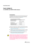
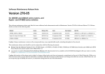
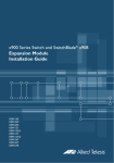
AR450S SECURITY APPLIANCE
QUICK INSTALL GUIDE
Software Release 2.5.2
AR450S Quick Install Guide
Document Number C613-04045-01 REV A.
Copyright © 2003 Allied Telesyn International, Corp.
19800 North Creek Parkway, Suite 200, Bothell, WA 98011, USA.
All rights reserved. No part of this publication may be reproduced without prior written
permission from Allied Telesyn.
Allied Telesyn International, Corp. reserves the right to make changes in specifications
and other information contained in this document without prior written notice. The
information provided herein is subject to change without notice. In no event shall Allied
Telesyn be liable for any incidental, special, indirect, or consequential damages
whatsoever, including but not limited to lost profits, arising out of or related to this
manual or the information contained herein, even if Allied Telesyn has been advised of,
known, or should have known, the possibility of such damages.
All trademarks are the property of their respective owners.
Quick Install Guide
3
Documentation Roadmap
AR450S Router
General Customer Support
AR400 Series Safety and Statutory Information
Visit www.alliedtelesyn.co.nz for
the latest documentation, FAQ,
and support information
AR450S Quick Install Guide
AR400 Series User Guide
AR400 Series Software Reference
AR Router Hardware Reference
Printed
Acrobat PDF
Website
Models Covered By This Guide
This Quick Install Guide includes information on the following model:
■
AR450S
Quick Install Guide updates can be found at
www.alliedtelesyn.co.nz/support/ar400/
Package Contents
The following items are included with each AR450S router. Contact your sales
representative if any items are damaged or missing.
C613-04045-01 REV A
■
One AR450S router.
■
One AC power cord.
■
One power cord retaining clip.
■
One terminal cable for connecting the router to a terminal or PC.
■
Two UTP network cables.
■
One rack-mount kit with brackets and screws.
■
One AR450S Router Quick Install Guide.
■
One Safety and Statutory Information booklet.
■
One AR400 Series Router Documentation and Tools CD-ROM (which
includes the complete AR400 Series Document Set and utilities).
■
One warranty card.
4
AR450S Router
Selecting a Site
The router should be installed on a level surface such as a desktop or bench.
When installing the router, choose a site that:
■
Allows adequate airflow around the router and its vents.
■
Is free of dust and moisture.
■
Will maintain an ambient temperature range of 0 to 40º C (32 to 104º F) and
a humidity range of 5 to 95% non-condensing.
■
Has a reliable and earthed (grounded) power supply circuit, preferably
dedicated and filtered.
■
Does not expose cabling to sources of electrical noise, such as radios,
transmitters, broadband amplifiers, power lines, electric motors, and
fluorescent fixtures.
■
Allows easy access to the router’s power and cable connections.
Installing the Router
This equipment must be earthed.
Follow these steps to install the router:
1.
Read the safety information.
For safety information, see the Safety and Statutory Information booklet. A
copy of this booklet is supplied with each router, and can also be found on
the Documentation and Tools CD-ROM or at
www.alliedtelesyn.co.nz/support/ar400/
2.
Unpack the router.
Verify the package contents. If any items are damaged or missing, contact
your sales representative.
3.
Place the router in its operating location.
See the previous Selecting a Site section for guidelines on choosing a
suitable location.
4.
Check the supply voltage and the router’s rated voltage.
AR450S routers are fitted with a universal mains power supply that will
function over the range 100-240 VAC and 50–60Hz.
The specific power supply requirements for a particular model are clearly
displayed on the rear or underside of the router. If the supply is outside the
accepted range for the router, the router may not operate and damage to the
router may result.
C613-04045-01 REV A
Quick Install Guide
5
5.
Apply power to the router.
Fit the power cord retaining clip to the AC power inlet on the router’s rear
panel.
Connect the provided power cord to the AC power inlet and clip it in
place. Switch the router’s power switch to the ON position. The Power
LED will light continuously and the System LED will flash briefly. The Port
LEDs may also light briefly.
If the LEDs fail to light, the most likely cause is that the router is not
receiving power. Check that
•
The power supply outlet’s switch (if any), and the router’s power
switch, are in the ON position
•
The power cable is securely plugged in
•
The power supply is operational
If the LEDs light incorrectly, refer to the AR Router Hardware Reference for
troubleshooting information.
Figure 1: Front and rear panels of an AR450S, showing the AC power inlet, power switch, console ports and
Ethernet ports, and their associated LEDs.
Configuring the Router
AR450S routers can be configured via the Command Line Interface (CLI) or
Graphical User Interface (GUI).
Using the CLI to configure a router:
1.
Initiate router start-up.
Using the terminal cable supplied, connect a VT100-compatible terminal,
or the COM port of a PC running a terminal emulation program such as
Windows Terminal, to the Console RS-232 (ASYN0) port on the router’s
rear panel.
C613-04045-01 REV A
6
AR450S Router
Set the communication parameters on your terminal or terminal emulation
program to:
•
Baud rate: 9600
•
Data bits: 8
•
Parity: None
•
Stop bits: 1
•
Flow control: Hardware
See the AR Router Hardware Reference for more information on configuring
emulation software.
2.
Log in and set the password.
The log in prompt appears on the terminal or PC. If the log in prompt
doesn’t appear, press [Enter] two or three times.
When the router boots for the first time it automatically creates an account
with manager privileges. The account has the log in name “manager” and
the password is “friend”. Passwords are case sensitive.
At the log in prompt, enter the log in name and password.
Login: manager
Password: friend
The router’s command prompt appears and you can now configure the
router using the command line interface.
Change the password as soon as possible. Leaving the manager account with
the default password is a serious security risk. Make sure you remember the
new password as there is no way to retrieve it if it is lost.
Use the following command to change the account password:
set password
To display a list of help topics, enter:
help
To display help on a specific topic, enter:
help topic
Alternatively, type a question mark (?) at the end of a partially completed
command to see a list of valid options.
See the AR400 Series Router Software Reference for more information on
router start-up and configuration procedures (including a list of message
definitions).
Using the GUI to configure a router:
This section describes how to access the GUI via VLAN1, when the PC and
the router are in the same subnet, in order to configure the router. The
router’s five switch ports all belong to VLAN1 by default.
The GUI requires a PC and web browser. Supported browsers are Internet
Explorer 5.0 and greater, or Netscape 6.2.2 or 6.2.3, with JavaScript enabled.
Internet Explorer can be found on the Documentation and Tools CD-ROM
that is bundled with your router.
C613-04045-01 REV A
Quick Install Guide
7
1.
Connect the PC to a router switch port.
The PC can be connected directly, or through your LAN.
To connect the PC directly to the router, use a straight-through Ethernet
cable to connect an Ethernet card on the PC to any one of the router’s
switch ports. Note the PC’s IP address and mask.
To connect via a LAN, use a straight-through Ethernet cable to connect the
router’s switch port(s) to the device(s) on the LAN. Select the LAN PC
from which you wish to configure the router. The PC should be in the same
subnet as the part of the LAN that contains the router (for example, the PC
could be connected to a hub or Layer 2 switch that is directly connected to
one of the router’s switch ports). Note the PC’s IP address and mask.
Hub or
switch
2.
Access the CLI on the router.
Follow the instructions in the previous Using the CLI to configure a router
section.
3.
Enable IP.
At the CLI, enter the command:
ENABLE IP
C613-04045-01 REV A
8
AR450S Router
4.
Assign an IP address to VLAN1.
Assign the VLAN1 interface an IP address in the subnet that the PC uses,
using the command:
ADD IP INTERFACE=vlan1 IP=ipaddress MASK=mask
5.
Browse to the GUI.
If you access the Internet through a proxy server, set your browser to
bypass the proxy for the IP address you just assigned to the VLAN1
interface.
Point your web browser at the IP address of the VLAN interface.
6.
Log in and set the password.
At the log in prompt, enter the log in name and password. Passwords are
case sensitive.
User Name: manager
Password: friend
The system status page appears and you can now use the GUI to configure
the router.
To ensure configuration settings are saved correctly, use the GUI menus and buttons to
navigate, not your browser’s buttons.
As a security precaution, change the password as soon as possible.
To change the password, select Management > Users from the sidebar
menu. Select the Manager account and click Modify.
7.
To access context-sensitive help in the GUI.
Click on the Help Button [Help]. The Help button is located at the top of
the sidebar menu or on any popup page.
Connecting the Data Cables
Connecting the AR450S to your network:
1.
Connect to the LAN and DMZ.
If you have not already done so, use a straight-through Ethernet patch
cable to connect the device(s) on your private network (LAN) to the
router’s switch port(s). Two straight-through Ethernet patch cables are
supplied with the router. By default, all five switch ports are members of
VLAN1.
If you have a public server, use a straight-through Ethernet patch cable to
connect it to the router’s Ethernet DMZ (ETH1) port. Separating public
servers from your LAN allows the firewall to provide greater protection for
your LAN. If you have multiple public servers, you can connect them to a
hub or Layer 2 switch and connect that device to the router’s DMZ port.
C613-04045-01 REV A
Quick Install Guide
9
2.
Connect to the WAN.
If you intend to use a firewall, configure it before you activate the WAN link.
Once initial configuration is complete, use a straight-through Ethernet
patch cable to connect the router’s Ethernet WAN (ETH0) port to the
Ethernet port of a WAN device (such as a modem).
LEDs and What They Mean
LEDs indicate the router’s operational status and port activity.
AR450S System LEDs
LED
State
Function
Power
Green
The router is receiving power and the power
switch is in the ON position
System
Amber
The router is malfunctioning
Flashing
The fan has failed
Off
Normal operation
Green
The corresponding port is operating at fullduplex
Off
The corresponding port is operating at halfduplex
Green
A link has been established through the
corresponding port
Flashing
Data is being transmitted through the
corresponding port
Off
No link is present through the corresponding
port
Green
The corresponding port is operating at
100Mbps
Off
The corresponding port is operating at 10Mbps
Full Dup
Link/ACT
100M
C613-04045-01 REV A
10
AR450S Router
Troubleshooting Installation
If you have problems installing the router, try one or more of the following:
No LEDs Light
The most likely reason is that the router is not receiving power. Check the
following:
1.
Check the supply outlet’s switch is in the ON position.
2.
Test the mains power outlet to verify it is working.
If the problem persists, contact your authorised Allied Telesyn distributor or
reseller.
LEDs Light Incorrectly
If the System LED stays on, the router software has encountered a fatal
condition. Contact your authorised Allied Telesyn distributor or reseller.
No Response From the Terminal
1.
Is the terminal cable correct for both the terminal and the router? Test the
cable operation by connecting Txd and Rxd (pins 2 and 3) together at the
router end of the cable. Characters typed on the terminal should be echoed
back to the screen.
2.
Are the terminal or terminal emulation software communication
parameters set correctly? Refer to the AR Router Hardware Reference for more
information on setting communications parameters.
3.
Contact your authorised Allied Telesyn distributor or reseller for assistance.
Log in Name or Password Fails
1.
Passwords are case sensitive. Check your spelling and that you are using the
right combination of upper and lowercase characters.
2.
Contact your authorised Allied Telesyn distributor or reseller for assistance.
Documentation and Tools CD-ROM
The Documentation and Tools CD-ROM bundled with each router contains the
complete Document Set for your router. The CD-ROM also includes tools for
managing your router.
The Document Set includes:
■
The AR400 Series Router Safety and Statutory Information booklet, which
provides safety and statutory information.
■
This Quick Install Guide.
■
The AR400 Series User Guide, which provides an introduction to the router
and its operational features and characteristics.
■
The AR Router Hardware Reference, which provides detailed information on
the hardware features of AR routers.
C613-04045-01 REV A
Quick Install Guide
11
■
The AR400 Series Router Software Reference, which provides detailed
information on configuring the router and its software.
■
AT-TFTP Server for Windows, for downloading software releases.
■
Adobe Acrobat Reader, for viewing online documentation.
■
Microsoft Internet Explorer.
These documents can also be downloaded from the AR400 Series Router
Support Site at www.alliedtelesyn.co.nz/support/ar400/.
C613-04045-01 REV A