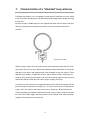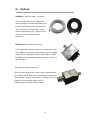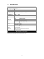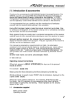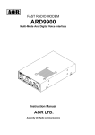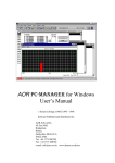
1
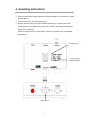
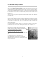
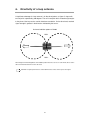
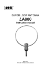
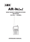
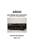
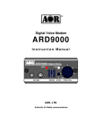
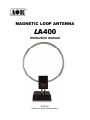
MAGNETIC LOOP ANTENNA
LA400
Instruction manual
AOR Ltd.
Authority On Radio Communications
2
Table of contents
1. Introduction
.........................................
4
2. Included in this package . . . . . . . . . . . . . . . . . . . . . . . . . . . . . . . . .
5
3. Hardware setup . . . . . . . . . . . . . . . . . . . . . . . . . . . . . . . . . . . . . .
6
4. Operating instructions . . . . . . . . . . . . . . . . . . . . . . . . . . . . . . . . . . 7
5. Remote tuning system . . . . . . . . . . . . . . . . . . . . . . . . . . . . . . . . .
9
6. Directivity of a loop antenna . . . . . . . . . . . . . . . . . . . . . . . . . . . . .
10
7. Characteristics of a “shielded” loop antenna . . . . . . . . . . . . . . . .
11
8. Options . . . . . . . . . . . . . . . . . . . . . . . . . . . . . . . . . . . . . . . . . . . . .
12
9. Specifications . . . . . . . . . . . . . . . . . . . . . . . . . . . . . . . . . . . . . . . .
13
3
1. Introduction
Thank you for purchasing the LA400 Magnetic loop antenna.
To get the best possible results from your LA400, we recommend that you read this manual
and familiarize yourself with the antenna.
Since the invention of this revolutionary concept by KOLSTER in 1915, loop antennas,
especially of the active type, have also been widely used by the military in the 70’s, before
becoming very popular among hobby listeners.
In recent years, the increase in man-made local noise (typical city noise) poses a problem
for the reception of distant signals in the long wave, medium wave and shortwave bands.
LA400 is our latest product based on the technology we developed since the original LA320
loop antenna. In addition to its exceptional directivity in order to minimize the effects of local
noise, the revolutionary LA400 offers, with its REMOTE TUNING SYSTEM, the perfect
solution to keep the antenna away from noise sources by setting it up in quiet areas!
While the control (tuning) box stays at hand’s reach, the loop element can be set away by
using simple LAN and BNC coaxial cables.
10kHz to 500MHz, 5 position band switch to peak only on the wanted signal. Small size
30.5cm diameter loop with exceptional 20dB gain
Remote tuning – Unlike previous amplified indoor loop antennas, the band switching and
fine tuning controls are not tied anymore to the loop element. With these controls now on
the control box and by using the LA400-RCK optional extension cables, it is now possible
to tune the antenna while the loop element is setup at the most reception friendly location
possible (window, covered balcony, etc...). Compatible with 3rd party cables. Maximum
length: 20m.
A relay system is used for band switching, providing excellent isolation characteristics.
The relay is efficiently placed inside the loop element, while you can operate it through the
control box via the control cable.
Electronic tuning from 150kHz 〜 30MHz allows very sharp tuning to the desired
frequency. Shift the aligning point slightly to attenuate unwanted signals while amplifying
the wanted signal.
4
2. Included in this package
No.
Description
Qty
①
Loop element
1
②
Control box
1
③
Control cable (LAN type) 30cm
1
④
1m coaxial cable (RG-58U with BNC (F)/BNC (F) connectors)
1
⑤
AC power supply
1
⑥
This printed instruction manual
1
③
①
④
②
5
⑤
3. Hardware setup
Caution!
LA400 is a RECEIVE ONLY antenna. Do not transmit with it or its circuitry will be severely
damaged, maybe even beyond repair.
As explained on the diagram below, attach the loop element to the control box, then connect
the coaxial and control cables. Finally, connect the AC power supply.
To connect LA400 to an antique receiver with 600Ω antenna terminal, use the optional
MC-600 Impedance Matching Transformer.
Loop element
①
To antenna input socket
Control box
of your receiver
②
Coaxial cable
Control cable
6
AC power supply
4. Operating instructions
◎ Connect the AC power supply and push the red power button on the control box. A blue
LED will light up.
◎ Tune your receiver to the desired frequency.
◎ Now you need to select one of the 5 available band ranges, using the band switch
numbered from 1 to 5. Refer to the printed switch number / band range information on
the top of the control box.
Please note that position 5 is non-tunable, as the loop is wired to act as an amplified
whip antenna.
5 selectable bands
10kHz to 150kHz
&
30MHz to 500MHz.
Band switch
7
◎ Peak the received signal by turning the TUNING knob slowly to either the left or the right.
The white dot on the tuning know helps you to see the approximate location of the tuning.
For your reference, when the dot is on top as on the above illustration, the tuning PEAK
is approximately in the middle of the selected band.
For example for band switch position 3 (3MHz to 10MHz), it would be roughly peaked on
6.5MHz.
Tuning is most critical above 3MHz. For best performance of LA400 and optimal
reception conditions, make sure the selected band is appropriate for the received
frequency, and search for the signal peak with the tuning know.
◎ A loop antenna is very directional. Rotate the loop element until your receiver’s signal
strength meter (S-meter) deflects to maximum and the incoming signal sounds clearest.
If your receiver does not have an S-meter, simply adjust for maximum received signal.
Rotate the loop element until the signal is strongest and any interfering signal is nulled.
8
5.Remote tuning system
With its unique REMOTE TUNING SYSTEM, the band switching and fine tuning controls are
not tied anymore to the loop element. With these controls now on the control box and by
using the optional LA400-RCK extension cables, it is now possible to tune the antenna while
the loop element is setup at the most reception friendly location possible (window, covered
balcony, etc...).
You can of course use generic straight LAN and RG-58U 50Ω coaxial cables. Maximum
length: 20m each.
Please note that TUNING knob positions might vary depending on the length of the remote
cables. This is due to slight variations of the voltage supplied to the loop element, depending
on the length of the remote cables. This is not a malfunction and does not diminish the
antenna’s performance.
For optimal reception conditions, always try to setup the loop antenna as far away as
possible from noise sources such as switching power supplies, TVs, computers, etc…
Ideal locations to remotely setup the loop element are
windows, curtain rails and even better, covered balconies, as
long as the loop element does not get wet!
Remember that LA400 is NOT WATERPROOF!
It is highly advised to put the loop antenna back indoors, after
use.
For window mounting, it is a good idea to use a
(non-supplied) plastic suction hook, as illustrated here.
Alternatively you can also use a (non-supplied) nylon cord to
hang it to a curtain rail.
9
6.
Directivity of a loop antenna
A significant advantage of a loop antenna is its directional pattern, a “figure 8” shape with
two null points separated by 180 degrees. The null in reception that is located at right angles
to the plane of the loop can be used for interference reduction. On the other hand, received
signal strength is greatest in the directions indicated by the arrows.
Horizontal radiation pattern of LA400
NULL
NULL
NULL: Angle from which magnitude of the radiation pattern decreases to zero. In other words, these are the
sides from which the antenna receives the least.
Maximum reception performance is achieved when these sides of the loop face the signal.
10
7.
Characteristics of a “shielded” loop antenna
A shielded loop antenna is less susceptible to nearby electrical interference sources, thanks
to the electrostatic shielding of the loop afforded by the grounded metallic conduit enclosing
the wire coils.
By these principles, LA400 responds to the magnetic field rather than the electric field, thus
efficiently isolating the low frequency electrostatic noise from the distant signal to be
received.
Shield circuit of LA400
With this design, all parts of the loop will have the same capacitance to ground. The shield
also protects the loop from the induction field created by nearby disturbances. The induction
field refers to the electric and magnetic fields in the immediate vicinity of an antenna. Those
fields decrease rapidly in strength with distance, and the induction field is usually ignored.
However, wires and other metal objects near the loop can take energy from a passing wave
and produce induction fields that can induce spurious voltages in the loop.
A shield over a loop antenna will not appreciably decrease the amount of magnetic flux that
passes through the loop when a wave goes by - as long as it does not form a complete turn.
A gap is left in the shield so that it does not become a shorted turn. Without the gap, the
shield would reduce the magnetic field linking the loop so that no signal could be received by
the internal wire. With the gap, alternating currents can be induced in the metal shield and
voltages will be induced in the internal wire.
11
8.
Options
LA400-RCK Extension cables (10m each)
This set of cables allows you to separate the
control (tuning) box from the loop element, by up
to 10m. Conveniently place the loop element as
closely as possible to an open space, such as
window, covered balcony, etc...away from local
electrical noise, for a quieter reception
experience.
MC-600 Impedance matching transformer
Passive impedance matching transformer interface which allows
your LA400 to be connected to any antique receiver with a 600Ω
antenna terminal. Supported frequency range: 10kHz to 30MHz.
MC-600 has the same isolation feature than the GT-1 accessory
described below.
GT-1 Galvanic isolation transformer
To be connected between the receiver and the LA400 antenna.
Does greatly reduce local noise by breaking the ground loop
effect between antenna and receiver, especially when the
LA400-RCK 10m separation cables are used.
Supported frequency range: 40kHz to 30MHz
12
9.
Specifications
LA400 Magnetic loop antenna
Frequency range
10kHz 〜 500MHz
Aligned range
150kHz 〜 30MHz
Unaligned range
10kHz 〜 150kHz, 30MHz 〜 500MHz
Gain
20dB min.
Operating temp.
-10℃ 〜 +60℃
Power req.
9〜15V DC, 80mA @ 12VDC
Impedance
50Ω
4 band selectable
Loop
305mm diameter
Sizes (mm)
Loop element
305(W)x367(H)x38(D)
projections incl.
Control box
118(W)x59(H)x112(D)
All assembled
300(W)x425(H)x110(D)
Loop element
220g
Control box
300g
Weight
Control cable (LAN type) 30cm
Supplied
AC power supply
accessories
BNC (F)/BNC (F) RG-58U coaxial cable (1m)
Printed user manual
LA400 is NOT intended for transmit purposes!
Not waterproof, use only indoors.
Product specifications and design subject to change without prior notice.
13
®
AOR Ltd.
2-6-4 Misuji, Taito-ku, 111-0055 Tokyo, Japan
www.aorja.com
Authority On Radio Communications
-
(June 11, 2012)
14