1
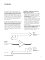
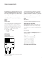
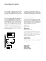
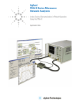
Introduction
The Agilent Technologies 8510C microwave network analyzer is an excellent instrument for measuring the transmission and reflection characteristics of many amplifiers and active devices. Scalar
parameters such as gain, gain flatness, gain compression, reverse isolation, return loss (SWR), and
gain drift versus time can be measured. Additionally,
vector parameters such as deviation from linear
phase, group delay, and complex impedance can
also be measured.
Two new features available with 8510C revision 7.0
firmware, power domain and receiver calibration,
allow for absolute power and nonlinear measurements such as gain compression. Since the 8510 is
a tuned receiver, it provides high dynamic range,
sensitivity and immunity to unwanted spurious
responses. Its accuracy-enhancement capabilities
reduce systematic errors for more precise characterization of the amplifier or active device under
test (AUT).
Agilent 8510C—Capabilities for measuring
amplifiers and active devices
• High output power at the test port (–15 dBm at
50 GHz for the 8517B Opt 007 test set) drives
high-power devices, eliminating the need for
external amplifiers.
• 0.02 dB power resolution provides precise control of the input power to the device.
• Power sweep (8 dB broadband, up to 26 dB narrowband for the 8510C with 8517B Opt 007 test
set, 1 dB broadband, up to 23 dB narrowband
with the 8515A, and 13 dB broadband, up to
23 dB narrowband with the 8514B) allows for
convenient gain compression measurements
(in dBm or mW).
• Power meter calibration improves measurement
accuracy and when combined with receiver calibration provides new capabilities such as
absolute output-power measurements.
• User-defined preset function saves setup time
and protects power-sensitive devices.
S21
Gain
Gain flatness
Gain drift
Deviation from linear phase
Group delay
Gain compression
S11
Input match
Input return loss
Input SWR
Input reflection coefficient
Input impedance
AUT
S22
Reverse isolation
Output match
Output return loss
Output SWR
Output reflection coefficient
Output impedance
S12
Figure 1. Amplifier parameters
3