1
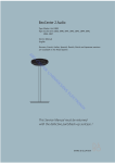
BeoSound 4 Type 2851, 2852, 2853, 2854, 2855, 2857, 2858, 2859, 2860 O AB Service Manual English German, French, Italian, Spanish, Danish, Dutch and Japanese versions are available in the Retail System R TE N E -C H v/ EN S EN KS RI T EK EL IK N RO This Service Manual must be returned with the defective parts/back-up suitcase ! CONTENTS Survey of modules ......................................................................................... 1.1 How to service ............................................................................................... 1.2 PIN-code ........................................................................................................ 1.3 O AB Warnings ....................................................................................................... 1.5 Final check after repair . ................................................................................. 1.6 E -C Fault flow chart ............................................................................................. 2.1 Placement of measuring points ...................................................................... 2.2 N TE Placement of magnet . ................................................................................. 2.11 Service mode ................................................................................................. 3.1 R Service tips .................................................................................................... 4.1 H v/ Repair tips ..................................................................................................... 4.2 EN Replacement of modules ............................................................................... 5.1 Specification guidelines for service use ........................................................... 6.1 RI Wiring diagram . ............................................................................................ 7.1 KS Available parts ............................................................................................... 8.1 S EN T EK EL IK N RO Survey of modules 1. Survey of modules 37 2 6 O AB 10 12 96 61 4 R TE N E -C 8 H v/ 5 85 4 7 Keyboard EN 3 5 9 S EN KS RI 1 11 T EK EL IK N Socket Master Magic Light Turn wheel Main microprocessor Codec Tacho Headphone Display SD/MMC card reader Switch DAB SMPS FM tuner EU/JP CD unit RO PCB1 ........................... PCB2 ........................... PCB3 ........................... PCB4 ........................... PCB5 ........................... PCB6 ........................... PCB7 ........................... PCB8 ........................... PCB9 ........................... PCB10 ......................... PCB11 ......................... PCB12 ......................... 37Module ................... PCB61 ......................... PCB85 ......................... 96Module ................... 1. How to service How to service Converting mains supply voltage The unit has separate type nos. for each market, due to country approvals. The mains voltage is determined by the type nos. of the unit, there are only two internal mains voltage settings (a jumper) on the SMPS, 100/120V and 230/240V AC (P108, when mounted = 100/120V). O AB Front line service R TE N E -C The BeoSound 4 unit has been developed for simple module exchange to follow the on-site service strategy. Module exchange is possible onsite, in the shop or in the service workshop whatever is most convenient in each case. For on-site service a back-up suitcase must be used. Module exchange is the recommended way to perform service, due to the fact that most of the modules are multi-layer based, and most of the circuits are on a single main PCB. An electrical fault symptom can be removed during one visit to the customer’s home, if you bring a BeoSound 4 back-up suitcase with you. Is it a mechanical symptom, the particular part must be brought with you separately. H v/ Service documentation Service documentation for BeoSound 4 will be a Service manual with part no. for the back-up suitcase, electrical and mechanical parts, user’s guides etc. EN S EN KS RI T EK EL IK N RO PIN-code 1. PIN-code The product has a 4 digit PIN-code, of the user´s own choice, which must be entered if the product has been disconnected from the mains for 15-30 min. If the PIN-code is activated, and the product has been without mains for 15-30 min., the user will be asked to enter the 4 digit PIN-code when the product is switched on. O AB Before the product is handed in to service it is a good idea to ask the customer to deactivate the PIN-code. The PIN-code is activated when the product is shipped from Bang & Olufsen. E -C Refer to the user guide for further information. PIN-code active prior to service Service code R TE N If the PIN-code is not deactivated prior to service you must use the Service code to unlock the product. Entering the Service code The service code unlocks the product, but does not affect the pin-code setting gives you 12 hours service time H v/ - - EN RI 1. When the product asks for PIN-CODE press and hold l for 3 seconds. 2. The Master code menu appears. 3. Enter the Service code: 1 1 1 1 1. EN KS Important notice concerning Service time The service time is active as long as the product is connected to the mains, including Standby. S To obtain maximum service time: Only connect the product to the mains while you are performing actual service on the product. T EK EL When the service time is expired, the product can only be unlocked by entering the PIN-code or the Master code. Registration of the modules N - RO - The modules will be registered to the product in the following situations: the product has been connected to the mains for more than 12 hours, including Standby time. the PIN-code is activated or deactivated. IK PIN-code deactivated by customer prior to service With the PIN-code deactivated prior to service you must be aware of the modules will be registered to the product in the following situations: - the product has been connected to the mains for more than 12 hours, including Standby time. - the PIN-code is activated or deactivated. The registration of modules in the product can only be changed at Bang & Olufsen. 1. PIN-code Activate the PIN-code Select the SETUP menu. Press l twice and then STOP to bring up the PINCODE SETUP menu. Enter the 4 digit Pin-code. Re-enter the code to confirm it and press GO. If you want to change or delete the PIN-code, enter the correct PIN-code and press GO. It is now possible to change the PIN-code or delete the PIN-code. O AB Enter the PIN-code E -C If the PIN-code is activated and the product is disconnected from the mains for more than15-30 minutes, a PINCODE menu appears as soon as the product is switched on. Enter the PIN-code, and the product starts again. If the PIN-code has been forgotten the only way to unlock the product again is by entering a 5 digit Master-code. The Master-code is ordered by sending a request via the Retail System. When the product prompts for a PIN-code, press and hold l down to bring up the MASTERCODE menu. Enter the Master-code and press GO. This will deactivate the PIN-code and reactivate the product. R TE N If the PIN-code has been forgotten H v/ EN Product locked by PIN-code The product is locked by PIN-code when: RI - The PIN-code is activated and the mains is disconnected for more than 15- 30 minutes. KS The product is unlocked when the PIN-code is entered. EN S The PIN-code counter is set to 5 attempts within 3 hours. When a wrong PIN-code has been entered 5 times within 3 hours, the product cannot receive any commands for a period of 3 hours. After this period the PIN-code counter is reset. The product must be in standby mode to activate the timer. T EK EL IK N RO Warnings 1. Warnings ESD O AB When electrical replacements or disassembly all taking place, use an ESD-mat. The internal electronics are very sensitive to static electricity. When mains voltage on BeoSound 4 is required, remove the connection from BeoSound 4 to the ESD mat. E -C STATIC ELECTRICITY MAY DESTROY THE PRODUCT Laser exposure R TE N BeoSound 4 contains a laser system and is classified as a class 1 laser product. BeoSound 4 must be opened by qualified personal only. H v/ EN General warnings CLASS 1 LASER PRODUCT EN Cleaning KS RI Wear cotton gloves to avoid fingerprints on the product. The display surface on the product is very sensitive, so handling should be done with great care to avoid damage. When transporting BeoSound 4, it is recommended to use the product cover, part no. 3375490. Be sure that the plugs in each end are connected correctly. S Clean BeoSound 4 surfaces using DuPont Polishing Cloth, part no. 3624018. Finally clean the front glass with DuPont Final Tack Cloth. It prevents electrostatic buildup. Never use alcohol or other solvents to clean any parts of BeoSound 4. T EK EL IK N RO 1. Final check after repair Final check after repair Isolation test O AB Each set must be insulation tested after having been dismantled. Make the test when the set has been reassembled and is ready to be returned to the customer. Flashovers must not occur during the testing procedure! Make the insulation test as follows: Short-circuit the two pins of the mains plug and connect them to one of the terminals of the insulation tester. Connect the other terminal of the insulation tester to the chassis pin of the aerial socket. TE N E -C NOTE! To avoid damaging the set, it is essential that both terminals of the insulation tester have good contact. Slowly turn the voltage control of the insulation tester until a voltage of 2.5 kV and max. 5 mA is obtained. Maintain that voltage for one second, and then slowly turn it down again. Isolation test at the customer R Remove the mains cable from the wall outlet. Place a jumper across the two AC plug prongs. Use a multi-meter, set for measurements in the ohm-area. Place one lead from the multi-meter on the AC plug and place the other lead on ground at the power link plug. The resistance during this measurement must be of 1 mega ohm or more. Resistance measured below 1 mega ohm indicates an abnormal situation and corrective action must be taken. H v/ EN Test of the device S EN KS RI 1. 2. 3. 4. 5. 6. After the insulation test, it is important to do the final test of the device, to make sure there are no other faults. Turn on BeoSound 4 and load a CD. Play the CD. Switch to SD play mode. Switch to FM radio and make a tuning. Switch to DAB radio and make a tuning. Use volume up/down. Make sure that both the remote control and the buttons work perfectly. T EK EL Before finishing the device, make sure that the option setting is correct. IK N RO Fault flow chart 2. Fault flow chart Instructions • • O AB • Instructions before trouble shooting in the fault flow chart: In the following fault flow chart BeoSound 4 is named BS4. Never connect or disconnect a socket, when the power is turned on. Disconnect the mains supply and wait minimum 30 seconds for the electrolytic capacitors to discharge. When measuring voltages BS4 must be in CD mode, When fault finding in CD use Bang & Olufsens test CD 3634031 (SBC444A). R TE N E -C H v/ EN S EN KS RI T EK EL IK N RO 2. Fault flow chart Placement of measuring points 6V - IC1000 pin1 5V_CD - IC1000 pin5 O AB 9V_CD Mains supply - P101 N E -C R TE 5V_SB 12V - IC1 pin8 -12V - IC1 pin4 H v/ EN S EN KS RI T EK EL IK N RO Fault flow chart 2. @uPH8 6V 5V_CD O AB 9V_CD R TE N E -C Mains supply P101 H v/ EN EN KS RI @back of display S 5V_SB T EK EL -12V +12V IK N RO @Headphone jack 2. Fault flow chart No Yes O AB Fault symptom: - Fault in voltages Possible causes: - PCB61, SMPS - Connections Measure connection to Socket, PCB1 OK? Measure 12V, -12V, 6V 5V_SB OK? Measure all connections in BS4 are all right Re-establish connection R TE N E -C Measure mains supply Fuse F101 OK? H v/ EN Change PCB61, SMPS Use menu to change sensitivity of the door censors OK? Lift the front glass a little Push “Load” Front glass opens S EN Possible causes: - Bright light shining on the product - PCB3, Magic KS RI Fault symptom: - Front glass does not close Measure connections or replace PCB3, Magic IK N RO Move BS4 to another place OK? T EK EL BS4 is placed in bright light? Fault flow chart 2. No Yes O AB Fault symptom: - No stand-by light - Unable to use/remote BS4 Possible causes: - PCB61, SMPS - Fuse F101 Replace defect fuse Connections from PCB61 to other boards OK? Re-create connection R TE N E -C Measure mains supply Fuse F101 OK? H v/ Replace PCB61, SMPS EN Possible causes: - PCB9, headphone connector - PCB2, Master EN KS RI Fault symptom: - No sound in headphone Switch to FM Sound in speaker? Plug another headphone Sound in headphone? Connection from PCB2 to PCB9 OK? Change PCB2, Master S Unplug headphone Sound in speaker? T EK EL Re-establish connection Change PCB2, Master IK N RO Change PCB9, Headphone 2. Fault flow chart No Yes Fault symptom: - Unable to remote with turn wheel O AB Both wheels defect Connection to PCB5, PCB3 and keyboard OK? Connection to PCB5, PCB3, PCB6 and keyboard OK? Re-establish connection Possible causes: - Connection not OK - Defect turn wheel - PCB3, Magic open defect Change defect PCB5, Turn wheel R TE N E -C H v/ Keyboard OK? Check option setting Change PCB2, Master Change cable T EK EL Measure connection to PCB61, SMPS RO Fault symptom: - No power - Stand-by led not lit - Unable to remote S EN KS Refer to user guide OK? Check ML cable e.g. try another cable Connect to another product OK? RI Possible causes: - Wrong option setting - ML cable - PCB2, Master EN Fault symptom: - Unable to use MasterLink Change PCB3, Magic Measure mains supply Fuse F101 OK? Change PCB61, SMPS Re-establish connection Change fuse IK N Possible causes: - PCB61, SMPS Fault flow chart 2. No Fault symptom: - Unable to play CD (test CD) - No disc rotation - Playback with SD card OK - Cable connection to CD PCB OK O AB Establish fault symptom with B&O Test CD Fault symptoms established? E -C Possible causes: - Focus problem - PCB76, CD board - PCB96, CD unit Clean lens with isopropyl alcohol and play disk N OK? Yes Establish the fault with customer’s CD Check the disk for visible defects Report fault and send the customer CD to B&O for analyse Measure supply voltages to CD mechanism PCB2, IC1000, pin1 - 6V PCB2, IC1003, pin2 - 12V Change PCB96, CD unit Change PCB2, Master Change PCB61, SMPS R TE Measure supply voltages to CD mechanism PCB2, IC100 pin5 - 5V PCB2, IC1003, pin4 - 9V Measure connections are correctly connected H v/ Establish the fault with customers CD Check the disk for visible defects Report fault and send the customer CD to B&O for analyse Establish fault symptom with B&O Test CD Fault symptoms established? Measure supply voltages to CD mechanism PCB2, IC100 pin5 - 5V PCB2, IC1003, pin4 - 9V Measure connections are correctly connected S Change PCB61, SMPS Change PCB2, Master IK N RO Change PCB96, CD unit Measure supply voltages to CD mechanism PCB2, IC1000, pin1 - 6V PCB2, IC1003, pin2 - 12V T EK EL OK? EN Clean lens with isopropyl alcohol and play disk KS RI Possible causes: - Tracking problem - Dirty lens - PCB76, CD board - PCB96, CD unit EN Fault symptom: - Regular dropouts/mute when playing CD - CD stops playing/rotating - CD search problem 2. Fault flow chart No Yes O AB Fault symptom: - Fault in display - Only a few lines are faulty Measure connections to the display is OK? Re-establish connection Change PCB10, Display OK? Change PCB2, Master Possible causes: - PCB10, display - Connections to display R TE N E -C Change PCB10, Display OK? Change PCB2, Master EN Measure voltages +12V Measure connections to tuner OK T EK EL Possible causes: - PCB85, tuner - PCB61, SMPS Replace PCB61, SMPS S Fault symptom: - Unable to play FM - CD plays OK EN KS RI Possible causes: - PCB10, display - Connections to display H v/ Fault symptom: - Fault in display - Nothing in display - Stand-by led OK - Able to remote - Able to play CD IK N RO Replace PCB85, tuner Fault flow chart 2. No Yes Fault symptom: - Unable to play DAB - CD plays OK - FM plays OK O AB Measure voltages +6V Replace PCB61, SMPS Possible causes: - PCB37, DAB - PCB61, SMPS E -C DAB aerial is mounted R TE N H v/ Measure connections to DAB OK EN RI Replace PCB37, DAB Lift the glass so the keyboard is visible Press the “Load” button The front glass slides up? Measure connection to PCB3, Magic BS4 in service position Measure connection to PCB3, Magic Confirm voltage 5V_SB & 6V Change PCB61, SMPS Change PCB3, Magic OK? Change PCB2, Master S Measure voltages 5V_SB & 6V Change PCB61, SMPS T EK EL Possible causes: - PCB3, Magic door censor - PCB61, SMPS - Motor EN KS Fault symptom: - Unable to open front glass RO Change PCB3, Magic Change PCB2, Master IK N 2.10 Fault flow chart No Yes Connection to PCB8, Tacho OK? Re-establish connection Change PCB8, Tacho OK? Replace PCB2, Master O AB Fault symptom: - The front glass slides to the top without stopping above the keyboard Possible causes: - PCB8, Tacho TE N E -C Replace motor unit H v/ EN Possible causes: - PCB12, Switch - PCB2, Master Check if the magnet on the door mechanism is mounted See figure page 2.11 R Fault symptom: - Unable to load CD - Front glass does not open - Front glass slides down a little and nothing else happens Change PCB2, Master S Door mechanism must be in lower position Measure 3.3V PCB12 P1 pin2 EN KS RI Measure connection to PCB8, Tacho & PCB12, Switch T EK EL Change PCB12, Switch Measure voltages OK? Change PCB61, SMPS Change PCB2, Master Change PCB1, Socket Possible causes: - PCB2, Master - PCB1, Socket IK N RO Fault symptom: - No sound in loudspeaker and/or headphone - Radio/DAB OK - CD OK Fault flow chart 2.11 Placement of magnet R TE N E -C O AB H v/ EN S EN KS RI T EK EL IK N RO 2.12 R TE N E -C O AB H v/ EN S EN KS RI T EK EL IK N RO R TE N e l p E -C O AB d te H v/ EN m o S EN KS RI o N c t 3. Service Mode T EK EL IK N RO Service Mode 3. R TE N E -C O AB e l p H v/ EN S EN o N c t KS RI m o d te T EK EL IK N RO Service tips 4. Service tips Service tool R TE N E -C O AB Along with a Cable kit for ServiceTool (3375397) and a P.I.T. box (3375055) it is possible to flash-update the FEP software. From the service module a special service cable goes to the BeoSound 4 unit. From the service module another service cable goes to a laptop. On the service module, you are able to select which software you want to flashupdate via a switch. You will need to get the ServiceTool program installed on your laptop, this can be downloaded from the Retail System. A fully described instruction is enclosed when the P.I.T. box is ordered (3375055). H v/ EN S EN KS RI T EK EL IK N RO 4. Repair tips Repair tips CD The diodes and the laser are very sensitive to static electricity. Damaging the diodes or laser may reduce their lives dramatically. So be sure, that the workstation is protected against static electricity. O AB The product may not be connected to the mains, when the CD mechanism or 96Module is removed. E -C Normally, the CD will find focus first, and when that has been found, it will start the turntable motor. This means that if the motor cannot start, the reason may be that focus has not been found. R TE N Exchange of the microprocessor and PCB2 When replacing the PCB6 remember to move the EEPROM 6IC6 from the defective PCB6 to the new PCB6, because it contains valuable data (serial no. and PIN code etc). The data is not transferred to the new module until you have been in contact with the PIN-code protection or after 12 hours of connection to the mains. This means that you can try out a new PCB6 without transferring the product’s serial no. etc. H v/ EN Note! When the serial number has been transferred to the microprocessor, it can only be used for this specific product; it must go back to Bang & Olufsen’s module repair department as an exchange module to be erased again. If the product functions are OK, and the PIN-code protection is also OK; there is no need to test the functionality of the PIN-code protection. KS RI S EN Exchange of software EEPROM on PCB6 When exchanging the EEPROM on PCB6, the data from the microprocessor will be written into the EEPROM, when selecting any source e.g. RADIO. It is possible to borrow an EEPROM from another BeoSound 4 to test, if there is suspicion of a fault in the original EEPROM. The EEPROM will always adopt the data from the main microprocessor. T EK EL Replacing of both PCB6 and EEPROM 6IC6 If both PCB6 and the EEPROM 6IC6 need to be replaced it is necessary to have them pre-programmed from Bang & Olufsen with the correct serial no., otherwise they will not work. Please contact Bang & Olufsen. IK N RO Replacement of modules 5. Replacement of modules Replacement of the PCB61 (SMPS) When replacing PCB61 (SMPS), remember to check jumper at 61P108 E -C O AB Mains voltage 115V = jumper at 61P108 must be mounted Mains voltage 220V = jumper at 61P108 must be removed Main R TE N 61P108 H v/ EN Replacement of the Main microcomputer PCB6 (µPH8) When replacing the PCB6 remember to move the EEPROM 6IC6 from the defective PCB6 to the new PCB6, because it contains valuable data (Serial no., PINcode etc.). The data is not transferred to the new module until you have been in contact with the PIN code protection or after 12 hours of connection to the mains. This means that you can try out a new PCB6 without transferring the products serial no. etc. EN KS RI Note! S When the serial number has been transferred to the micro-processor, it can only be used for this specific product; it must go back to Bang & Olufsen’s module repair department as an exchange module to be erased again. If the product functions are OK, and the PIN-code protection is also OK; there is no need to test the functionality of the PIN-code protection. T EK EL N RO Exchange of software EEPROM on PCB6 When exchanging the EEPROM on PCB6, the data from the micro-processor will be written into the EEPROM, when selecting any source e.g. RADIO. It is possible to borrow an EEPROM from another BeoSound 4 to test, if there is suspicion of a fault in the original EEPROM. The EEPROM will always adopt the data from the main micro-processor. IK Replacing of both PCB6 and EEPROM 6IC6 If both PCB6 and the EEPROM 6IC6 need to be replaced it is necessary to have them pre-programmed from Bang & Olufsen with the correct serial no., otherwise they will not work. Please contact Bang & Olufsen. 5. Replacement of modules Disassembly overview PCB Module name Page R TE N E -C O AB 1 Socket 5.5 2 Master 5.6 3 Magic 5.8 4 Light 5.9 5 Turn wheel 5.10 6 Main microprocessor 5.7 7 Codec 5.11 8 Tacho 5.12 9 Headphone 5.13 10 Display 5.14 11 SD/MMC card reader 5.15 12 Switch 5.16 DAB 5.20 61 SMPS 5.17 85 FM tuner 5.18 H v/ 37Module 96Module 5.19 5.21 Clamper cover 5.22 Clamper unit 5.23 Base 5.24 EN CD unit Cabinet RI Door mechanism 5.25 Drivebelt 5.26 KS 5.27 Keyboard 5.28 Motor 5.29 S EN Finger niche T EK EL IK N RO BeoSound 4 in service position 5. - Remove all cables E -C O AB R TE N - Push front glass to top position and remove it H v/ EN 4x TX10 S EN KS RI - Remove screw covers at top - and all screws T EK EL RO - Remove cables IK N Plug with lock! 8P1 and 5P2 8P1 8P3 5P2 5. Remove Chassis + 5.3 BeoSound 4 in Service Position - Remove screws at socket panel 3x TX10 E -C O AB TE N - Remove screws at front 4x R TX10 H v/ EN S 2P1002 2P1009 EN KS RI - Remove cables T EK EL IK N RO - Pull out chassis Replace PCB1, Socket 5. + 5.3 BeoSound 4 in Service Position + 5.4 Remove Chassis - Remove plugs 85P100 O AB 7P101 E -C TE N - Pull off socket cover Snap-locks! R H v/ EN KS RI - Remove plugs 1P7 S EN 1P1 T EK EL 4x TX20 IK GND! N RO - Remove screws 5. Replace PCB2, Master + 5.3 BeoSound 4 in Service Position + 5.4 Remove Chassis - Remove screws and release snaplocks 2x TX10 O AB ➁ - Remove plugs TE N E -C ➀ 76P103 2P1003 R H v/ EN KS RI - Remove electrical chassis from mechanical chassis S EN T EK EL RO - Remove cables PCB2 IK N 2P1004 2P1008 Replace PCB2, Master 5. - Remove screws 6x TX10 E -C O AB N - Remove plugs on the back of PCB2 TE 2P1005 2P1013 2P1010 R 2P1012 2P1011 H v/ EN S EN KS RI - Transfer EEPROM software T EK EL EEPROM IC3 PCB6 IC6 EEPROM IC SOCKET IK N RO Use IC-pliers for replacement (part no. 3629145) 5. Replace PCB3, Magic + 5.3 BeoSound 4 in Service Position + 5.4 Remove Chassis - Remove screws 2x TX7 E -C O AB R TE N - Remove PCB3, Magic H v/ ➀ EN ➁ ➀ KS RI - Remove PCB9, Headphone S EN ➀ ➁ ➀ T EK EL IK N RO Replace PCB4, Light 5. + 5.3 BeoSound 4 in Service Position + 5.27 Remove finger niche - Remove PCB4, Light R TE N E -C O AB H v/ EN S EN KS RI T EK EL IK N RO 5.10 Replace PCB5, Turn wheel and parts (left and right) + 5.3 BeoSound 4 in Service Position - Remove cable O AB 5P1 E -C TE N - Release snaplocks and push out ➀ Snaplock! R H v/ ➁ EN RI 2x TX10 S EN PCB5 KS - Dismantle turn wheel ➀ Wheel T EK EL Base IK N RO Replace PCB7, Codec 5.11 + 5.3 BeoSound 4 in Service Position + 5.4 Remove Chassis - Remove screws and release snaplock 2x TX10 O AB ➁ E -C ➀ R TE N - Remove electrical chassis from mechanical chassis H v/ EN S EN KS RI - Remove plugs 7P100 T EK EL 7P101 RO - Remove screw IK N 1x TX10 5.12 Replace PCB8, Tacho + 5.3 BeoSound 4 in Service Position + 5.4 Remove Chassis + 5.23 Remove Clamper unit - Remove screws and plug 3x TX10 E -C O AB R TE N - Remove screws P1 4x H v/ TX10 EN KS RI - Remove drive belt S EN T EK EL IK N 8P3 RO - Remove plug and gear wheel Replace PCB9, Headphone 5.13 + 5.3 BeoSound 4 in Service Position + 5.4 Remove Chassis ➀ + 5.8 Remove PCB3, Magic - Remove PCB9, Headphone ➁ ➀ R TE N E -C O AB H v/ EN S EN KS RI T EK EL IK N RO 5.14 Replace PCB10, Display + 5.3 BeoSound 4 in Service Position - Remove screws 3x TX10 Plug with lock! CON1 R TE N E -C O AB - Remove cable H v/ CON1 EN S EN KS RI T EK EL IK N RO Replace PCB11, SD/MMC card reader 5.15 + 5.3 BeoSound 4 in Service Position - Remove screws 2x TX6 E -C O AB R TE N - Pull out PCB11, SD/MMC card reader H v/ EN S EN KS RI T EK EL IK N RO 5.16 Replace PCB12, Switch + 5.3 BeoSound 4 in Service Position + 5.4 Remove Chassis - Remove screw R TE N E -C O AB H v/ EN S EN KS RI T EK EL IK N RO Replace PCB61, SMPS 5.17 + 5.3 BeoSound 4 in Service Position + 5.4 Remove Chassis - Remove screws and release snaplock 2x TX10 O AB ➁ E -C ➀ R TE N - Remove electrical chassis from mechanical chassis H v/ EN S EN KS RI - Remove plugs 7P100 T EK EL 7P101 RO - Remove screws IK N 4x TX10 5.18 Replace PCB85, FM tuner + 5.3 BeoSound 4 in Service Position + 5.4 Remove chassis - Remove screws 3x TX10 E -C O AB R TE N - Remove plugs on th back of PCB85 H v/ 85P106 85P103 85P100 EN S EN KS RI T EK EL IK N RO Replace 96Module, CD unit 5.19 + 5.3 BeoSound 4 in Service Position + 5.4 Remove Chassis - Remove screws and release snaplock 2x TX10 O AB ➁ E -C ➀ R TE N - Remove electrical chassis from mechanical chassis H v/ EN S EN KS RI - Remove screws IK N RO - Pull off CD unit T EK EL 4x TX10 5.20 Replace 37Module, DAB + 5.3 BeoSound 4 in Service Position + 5.4 Remove chassis - Remove plugs O AB 37P201 37P101 R TE N E -C - Remove screws 3x H v/ TX10 EN S EN KS RI T EK EL IK N RO Replace Cabinet 5.21 + 5.3 BeoSound 4 in Service Position + 5.4 Remove Chassis + 5.8 Remove PCB3, Magic + 5.24 Remove Base R TE N E -C O AB H v/ EN S EN KS RI T EK EL IK N RO 5.22 Replace clamper cover + 5.3 BeoSound 4 in Service Position + 5.4 Remove Chassis + 5.23 Remove Clamper unit - Release snaplocks R TE N E -C O AB H v/ EN S EN KS RI T EK EL IK N RO Replace Clamper unit 5.23 + 5.3 BeoSound 4 in Service Position + 5.4 Remove Chassis + 5.19 Remove CD unit - Remove screws 4x E -C O AB TX10 R TE N - Lift off clamper Note! Take care that the arm is placed correctly H v/ EN RI ! S EN KS T EK EL IK N RO 5.24 Replace Base + 5.3 BeoSound 4 in Service Position + 5.4 Remove Chassis - Remove screws O AB 4x TX10 R TE N E -C H v/ EN S EN KS RI T EK EL IK N RO Replace door mechanism 5.25 + 5.3 BeoSound 4 in Service Position + 5.4 Remove Chassis + 5.23 Remove Clamper unit + 5.12 Remove Motor unit - Check that the alignment is correct Scratch in the plastic R TE N E -C O AB H v/ EN S EN KS RI T EK EL IK N RO 5.26 Replace drivebelt + 5.3 BeoSound 4 in Service Position + 5.4 Remove Chassis + 5.23 Remove Clamper unit - Remove screws and plug 3x TX10 E -C O AB R TE N - Remove screws P1 4x H v/ TX10 EN S EN KS RI - Remove Drivebelt T EK EL IK N RO Replace Finger niche 5.27 + 5.3 BeoSound 4 in Service Position - Remove screws 4x TX6 E -C O AB R TE N - Remove finger niche Note: lift free of “lock” H v/ ➁ EN ➀ S EN KS RI T EK EL IK N RO 5.28 Replace keyboard + 5.3 BeoSound 4 in Service Position + 5.15 Remove SD/MMC card reader + 5.27 Remove finger niche 5P1 - Remove cables O AB 5P1 R TE N E -C - Remove screws 4x TX6 H v/ EN S EN KS RI - Pull out keyboard T EK EL IK N RO Replace motor 5.29 + 5.3 BeoSound 4 in Service Position + 5.4 Remove Chassis + 5.23 Remove Clamper unit - Remove screws and plug 3x TX10 E -C O AB P1 R TE N - Remove screws 4x H v/ TX10 EN S EN KS RI - Remove drivebelt T EK EL IK N 8P3 RO - Remove screws and plug 3x 5.30 R TE N E -C O AB H v/ EN S EN KS RI T EK EL IK N RO Specification guidelines for service use BeoSound 4 Type 2851 EU 230V Type 2852 GB 230V Type 2853 US120V Type 2854 JP100V Type 2855 AUS 240V Type 2857 TWN120V Type 2858 KOR 230V Type 2859 LAT 230V Type 2860 CHK 230V O AB Specification guidelines for service use With FM and RDS Preamplifier section Intermod. distortion Frequency: AUX in Signal to Noise ratio: AUX, A-weighted, volume 80 Channel separation Channel unbalance ≤0.1%, IHF E -C 20Hz – 20kHz N ≥90dB, typ. 97dB ≥50dB, typ. 63dB ≤±1dB TE R Tuner, FM section FM range – EU/US FM range for type 2854 – Japan Usable sensitivity mono 50dB quieting sensitivity mono Signal-to-noise ratio mono Signal-to-noise ratio stereo Frequency response mono Frequency response Stereo RDS 6. H v/ EN RI 87.5 – 108MHz 76 – 90MHz ≤12dBf ≤20dBf ≥68dB, typ. 70dB ≥62dB, typ. 65dB 30Hz – 15kHz, ±2dB 30Hz – 15kHz, ±2dB PS-Name, RadioText, Clock S EN KS Tuner, DAB section Receiving bands174 – 240MHz (band 3) 1452 – 1492MHz (band L) Sensitivity (BER = 10e-4) -95dBm Adjacent channel rejection (BER =10e-4) 35dB Out of band rejection (BER = 10e-4) 45dB Signal/noise ration (1kHz) ≥95dB Frequency response 15 – 20000Hz ±1dB Decoding Up to 256kbit/s Sampling Half and full rate T EK EL Beo4 recommended CD player Playback CD-DA, CD-R/RW, (Audio format only) ≥90dB / 76dB with volume 80 ≥98dB / 90dB with volume 80 ≥103dB / 97dB with volume 80 Channel separation: 1kHz 20Hz – 20kHz ≥85dB ≥75dB IK Signal/noise ratio: Linear, below 80kHz UNW A-Weighted N Testdisc SBC 444A (part no. 3634064) SBC 429 CD, disc types12cm (5”), 8cm (3”) Frequency response 20Hz – 20kHz ±1dB RO IR operation 6. Specification guidelines for service use Dynamic range (1kHz) Channel unbalance (1kHz) ≥92dB ≤±1dB THD+Noise: 1kHz, 0 dBFS, volume 76 -85dB / -75dB with volume 76 R TE N E -C O AB SD Player/recorder Storage media Secure Digital cards (SD) MultiMediaCard (MMC) Or 100% SD SanDisk compatible Capacity All capacity Audio Codec playback MP3 format: Sampling frequencies: 8, 11.025, 12, 16, 22.05, 24, 32, 44.1 and 48kHz Constant or variable bit rates: 8, 16, 24, 32, 40, 48, 56, 64, 80, 96, 112, 128, 160, 192, 256 and 320Kbps WMA: Sampling frequencies: 8, 11.025, 16, 22.050, 32, 44.1 and 48kHz Bit rates: 64, 80, 96, 128, 160 and 192Kbps Audio codec recording format MP3 format CBR @128kbit/s in stereo 44.1kHz sample frequency ≥16 bit sample resolution H v/ Testdisc: SBC429, Bitrate: 128kbit/sec, Codec: MPEG 1 Layer 3 Frequency response: Recorded from CD, fs = 44.1kHz KS 280 x 310 x 240mm / 11.0 x 12.2 x 9.4 in 4kg Smoke coloured glass Stby. 1W, typical 12W T EK EL Type 2180 Type 2181 S EN Accessories Floorstand Wall brackets ≥76dB ≥90dB ≥97dB RI Dimensions W x H x D Weight Cabinet finish Power consumption EN Signal/noise ratio: LINEAR, below 80kHz UNW A-Weighted 20Hz – 15kHz ±1dB IK N RO Connections Pin 1 Data- -0.25V Master Link x 1 Pin 2 Data+ +0.25V Pin 3 ML sense 0 – 5V Pin 4-8 NC Pin 9 ATI/Tx Pin 10 ATI/Rx Pin 11 Supply voltage -7V > -15V, stby. -3V > -15V Pin 12 Supply voltage 7V >15V, stby. 3V >15V Pin 13 Audio L1V bal., Rin 2.2MW Rout 75W Pin 14 Audio L+ 1V bal., Rin 2.2MW Rout 75W Pin 15 Audio R1V bal., Rin 2.2MW Rout 75W Pin 16 Audio R+ 1V bal., Rin 2.2MW Rout 75W Specification guidelines for service use 6. AUX in L/R AUX out L/R Power Link Front & Rear Pin 1 Pin 2 Pin 3 Pin 4 Pin 5 Pin 6 Pin 7 Pin 8 Headphones x 1 Sound level experienced should be the same using Form 1 headphones and BeoLab 4000 speakers Phono 2V RMS 22 – 47kW Phono 1.3V RMS ±0.2 <1kW PL ON = >2.5V, OFF = <0.5V Signal GND Audio L out 0V to 2V RMS PL speaker ON = >2.5V, OFF = <0.5V Audio R out 0V to 2V RMS Data: High >3.5V. Low <0.8V Data GND Not used TE N E -C O AB Audio Aux Input/Output x 1 Output level, -0dBFS, volume 72, RL 33W Signal/Noise ratio, A-weighted, -0dBFS, vol. 72 75W impedance H v/ DAB aerial x 1 R FM Aerial x 1 Max 1.4VRMS ≥92dB without clipping 75W impedance EN Mains Cable included 187 – 264V, 50 – 60Hz Type: 2851, 2852, 2855, 2858, 2859, 2860 Phase 58 – 132V, 50 – 60 Hz Earth Type: 2853, 2854, 2857 S EN KS RI Subject to change without notice T EK EL IK N RO 6. R TE N E -C O AB H v/ EN S EN KS RI T EK EL IK N RO Wiring diagram AB Wiring diagram P1 10 < < >< >< >< >< >< 05 TE N Turn Wheel > > > > P1 Turn Wheel P2 > > < < > > > > > > > > > > > > < > > > > R < > > 03 Magic < 04 P1 Light P1 < 6277878 W04 < P1 04 P1 Light < 6277875 W10 < P3 P3 P1 Switch < > 6200100 W16 < > P2 < < Master 6200095 W09 < < < < < < < < < < > > > > > > > > > > > > > > > > > > > > > > >< >< < < < < < < 6277877 W18 < > P1009 > > > > < > > P1003 6200098 W11 P1008 < P1004 KS < < >< >< > > > > > > < < < < > < < < > > < < < > CD unit < P101 96 CD unit P102 > < < P100 Head phone > > > > > > > > > > > > > > < > > < > < < < < < < < < < < < < < < < < > > < < < > > > > > < < < > > > > < >< >< >< >< > > > > 06 Main microcomputer P1005 > < < < < >< < < < < < < < >< < < < < < < < < < > < < < > > > > >< > > > > > > < < < > < < < > > > > >< > > > > > > < < < < < < < < < < < < < 6277707 W20 < P102 61 SMPS < 6277708 W21 <> <> > > P1006 P101 85 6270881 W24 < < < < 6270864 W25 FM Tuner 01 <> <> Socket > > 6200103 W23 P1013 < < 6200357 W14 < < < < > < >< >< >< >< > > > > < < 6277876 W15 P1 < < < < < < < < > > > > > > > < > > > > > > > > > < > > > > <> <> <> <> >< >< < <> <> <> <> >< >< < > <> < > > > > > > > > IK N < < < < < < > O < > > > > > > > 6200099 W12 P103 P7 09 TR < < < > > > < > > > < P2 EK EL >< P1007 S > > < P2 96 6200357 W13 EN > > < > > < < Codec > > < < >< >< >< > > < < > > > > < > > > < < < < >< 6200104 W17 > > > P1 >< 6277880 W27 > SD/MMC card reader 07 > > > >< >< 08 P101 > > > >< >< P100 6200093 W26 >< >< < < Tacho 37 Tuner DAB P101 < < > > 37 DAB > > > > > > >< >< 11 P102 6200355 W22 P1010 >< >< < > CN1 FFC 0.5mm 30/30pins Socket P1002 7211386 RI EN P1 < 12 P102 < < >< >< >< >< >< > 6277884 W28 < 7.1 P1001 H v/ 2/2pins < < < < Wiring diagram 02 E -C O P1 6200094 W08 7.1 Display P1 05 < < < < 7.1 > > > > > > 8.1 Available parts 8.1 Available parts AB Available parts BeoSound 4 8.1 9004 1 O E -C 3 3 1 3 TE N See page 8.5 Incl. PCB12 See page 8.4 2 1 10 1 9008 1 5 4 5 4 5 1 5 4 1 1 6 6 9009 W9 EN 3 Incl. pos. nos. 9011, W9, PCB9 9 S 9010 EK EL 9003 Incl. pos. no. 5 9007 5 KS 9002 1 RI EN 1 1 Incl. pos. no. 5 1 12 See page 8.3 9006 1 H v/ 9001 3 R 1 9005 1 9011 TR IK N O Available parts BeoSound 4 R TE N E -C O AB 3110018 3162231 3162228 3341017 3341014 3430045 3103136 3151913 6100079 6100084 6100247 6100248 6100306 6100089 6100386 3333050 8480389 Movable mechanics incl. PCB12 Front Glass Screw cover, left Screw cover, right Cabinet Base incl. pos. no. 5 Wire guide incl. pos. no. 5 Mains cable EU/LAT Mains cable UK Mains cable JP Mains cable AUS Mains cable US/TWN Mains cable CHINA Mains cable KOR Packing f/headphone Dynamic speaker W9 6200095 Wire 30 pole 3Module 3110016 PCB3, Magic incl. pos. nos. 9011, W9, PCB9 9Module 8002412 PCB9, Headphone 10Module 8337004 PCB10, Display H v/ Screws etc. 9001 9002 9003 9004 9005 9006 9007 9008 9009 9010 9011 12Module 8002400 PCB12, Switch 1 2 3 4 5 6 Screw 3 x 10mm Screw 2 x 5mm Screw 3 x 16mm Screw 4 x 12mm Rubber foot Screw 2.5 x 8mm EN 2052011 2052029 2054011 2019035 3103274 2011048 8.2 S EN KS RI T EK EL IK N RO 8.3 Available parts Front 4 9012 7 7 Incl. 2 x PCB4 7 4 O AB 9013 7 Incl. pos. no. 9016 TE N E -C 9016 R 7 H v/ 7 EN KS RI 1 Incl. PCB5 1 5 EN 9014 7 7 S 7 7 1 9015 T EK EL 11 1 5 RO Incl. PCB5 Finger niche incl. 2 x PCB4 Front cover incl. pos. no. 9016 Set of wheels incl PCB5 Keyboard Cover 4Module 8002409 PCB4, Light 5Module 8002410 PCB5, Turn wheel 11Module 8002405 SD/MMC card reader 1 7 Screw 3 x 10mm Screw 6 x 25mm 2052011 2013034 IK Screws 3162232 3162233 2791022 3167040 3162217 N 9012 9013 9014 9015 9016 9014 Available parts CD unit and Motor 8.4 9018 1 1 O AB 1 9017 E -C 1 1 TE N R 96Module H v/ 1 1 1 EN 1 1 1 1 1 KS RI 1 S 1 EN 1 9020 8 T EK EL 9019 RO 9021 IK N 9017 9018 9019 9020 9021 Screws 3320949 3162230 2755082 2732127 8400025 CD unit Clamper cover Gear unit Belt Motor 8Module 8002530 PCB8, Tacho 96Module 8420024 CD unit 1 Screw 3 x 10mm 2052011 8.5 Available parts Electrical chassis 1 9025 1 1 37 1 O AB 6 1 1 1 1 1 1 1 1 H v/ 61 9030 EN 1 1 1 RI 9027 1 S 1 EN 1 7 1 KS 85 3110010 3110012 3110011 2570016 3110013 3160344 Holder f/PCB2 and PCB37 Holder f/PCB61 Holder f/PCB7 and PCB85 Ground connector Holder f/PCB1 Cover PCB2, Master incl. PCB6 6Module 8000138 8343712 PCB6, Main microprocessor SW IC EEPROM 7Module 8002595 PCB7, Codec 37Module 8002046 DAB 61Module 8002594 7221406 PCB61, SMPS Shunt 85Module 8002415 8002417 PCB85, FM tuner EU PCB85, FM tuner JP 1 Screw 3 x 10mm 2052011 IK 2Module 8002593 N PCB1, Socket RO 1Module 8002592 T EK EL 9025 9026 9027 9028 9029 9030 Screws 1 1 R 1 1 TE 1 9029 1 1 N 1 9026 9028 1 E -C 1 2 Available parts Wire bundles See wiring diagram page 7.1. The part no. is printed on the diagram above the wire bundle, as shown. P1 10 < < < < 6200094 W08 < < < < P1001 Display 02 E -C O AB < < >< >< >< >< >< Parts not shown R TE N ServiceTool 8.6 3395296 3375490 3634031 3624018 H v/ 3375055 3375397 6270857 6270852 6277439 8008922 > > > > > < < < < < < < Master Back-up suitcase Product cover Test CD - SBC 444A Du Pont Polishing Cloth EN P.I.T. box ServiceTool – download from Retail System / BeoWise Cable kit for ServiceTool, complete Cable kit consists of: Main cable Cable D-SUB-Jack Wire, 3 pole Minijack f/STB-Controller RI Accessories See Retail Ordering System 8720063 8720044 FM dipol antenna DAB antenna S EN KS Available documentation T EK EL IK N RO 8.7 Available parts Packing 9301 9301 R TE N E -C O AB 9302 H v/ EN 9303 Foam, set of top and bottom Foam foil Outer carton S 3396308 3917143 3392385 EN KS RI 9301 9302 9303 T EK EL IK N RO Available parts 8.8 Floor Stand 2180 1218011 9102 1 Incl. pos. nos. 9102, 1 3 9301 3 3 R TE N E -C O AB 9101 9302 H v/ EN KS RI 9301 9103 EN S 9303 T EK EL 9104 2 1 2 3 2046017 3390065 2019035 Screw 6 x 16mm Bag w/parts Screw 4 x 12mm 9301 9302 9303 3396329 3016011 3392485 Foam packing, set Guide f/cover plate Outer carton 3390083 3507399 3507661 Cable manager Guide Guide f/cable manager IK Tube incl. pos. nos. 9102, 1 Cable clip Cover plate Rubber foot N 3932012 2369003 3162237 3103391 RO 9101 9102 9103 9104 8.9 Available parts Wall bracket 2181 1218111 O AB E -C 3 3 3 2019035 Screw 4 x 12mm 3390071 3507400 Bag w/parts Guide H v/ R TE N 3 EN S EN KS RI T EK EL IK N RO R TE N E -C O AB H v/ EN S EN KS RI T EK EL IK N RO R TE N E -C O AB H v/ EN S EN KS RI T EK EL IK N RO Bang & Olufsen DK-7600 Struer Denmark Phone +45 96 84 11 22* Fax +45 97 85 39 11 3538035 04-06