1
Select receive bandwidth: For point-to-point
communications a bandwidth of 15 kHz usually provides
best results, however if adjacent channel interference is
experienced a bandwidth of 6 kHz may provide better
to access the I.F. bandwidth
results. Press
menu then use the SUB DIAL to make the selection (in this
to accept the
example select 15 kHz). Press
selection and return to VFO mode.
If the MAIN DIAL is rotated the frequency will increment in
10 kHz steps but the trailing 1.25 kHz will remain in place...
27.60125 MHz, 27.61125 MHz, 27.62125 MHz etc.
The trailing digits will not be set to zero enabling tracking
of unusual band plans.
The MAIN DIAL follows the adjusted frequency
bandplan while the SUB DIAL kills the trailing digits
and steps rigorously in round numbers.
To cancel step-adjust
The easiest way to cancel step-adjust is to return to
key for more
AUTOMODE, press and hold the
than one second. Step-adjust will be cancelled and the
frequency will hop to the nearest whole increment as
determined by the automode bandplan data.
You may also cancel step-adjust using the STEP MENU.
to activate the step menu. If step-adjust is
Press
active, the legend “*” will be displayed on the left of the
LCD. Press
to toggle the step-adjust facility On/
to return
Off. To accept the change to OFF, press
to VFO mode.
Note: You may review the step-adjust value quite simply...
While in VFO mode, press
followed by
to
access the step-adjust sub menu. In the above example
the step-adjust value will be 2.0 kHz, refer to the following
text for the mathematical explanation... this is not
essential but makes good bedtime reading!!!
Application of arithmetic for the step-adjust
For those who wish further information on the
mathematics involved... the AR5000 works this out for
you automatically! The following examples should explain
how the step-adjust works in theory.
If the frequencies you need to search are allocated as:
145.210 145.224 145.238 145.252 145.266 145.280
145.294 145.308 (MHz)
Check the stepping size at first:
145.224 - 145.210 = 0.014 STEP SIZE (MHz)
Now you have found that each frequency is allocated
with a 0.014 MHz (14kHz) spacing you now have to
calculate the value of the internal processing frequency:
145.210 / 0.014 = 10372.14285
This should be rounded as 10372 INTERNAL
PROCESSING VALUE
To obtain the internal processing frequency, multiply the
STEP SIZE by the INTERNAL PROCESSING VALUE:
0.014 x 10372 = 145.208 INTERNAL PROCESSING
FREQUENCY (in MHz).
Now calculate the STEP-ADJUST VALUE by subtracting
the INTERNAL PROCESSING FREQUENCY from the
DESIRED FREQUENCY:
Another example:
If the frequencies you need to search are allocated as:
145.210 - 145.208 = 0.002 (MHz)
STEP-ADJUST VALUE
145.210 145.224 145.238 145.252 145.266 145.280
145.294 145.308
It can be concluded that a step-adjust value of 2 kHz is
required.
Check the stepping size at first:
145.224 - 145.210 = 0.014 STEP SIZE
In order to step through the above frequency
allocation you need to apply a STEP SIZE OF 14 kHz
with a 2 kHz STEP-ADJUST.
To enter this step size and data using the easiest method!
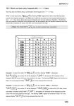
To apply a step size of 14 kHz and step-adjust of 2kHz:
First key in the start frequency while in VFO mode:
= 2 kHz
Select VFO mode by pressing
, select the desired
VFO (displayed in the right hand lower corner of the LCD).
Select the step menu by pressing
Press
Key in the required step size:
to select STEP-ADJUST. The legend
Press
“*” will appear on the left of the display to confirm selection
of step-adjust.
Select step-adjust by pressing the
key, the legend
“*” appears on the left of the LCD to confirm selection.
Complete the entry by pressing
The MAIN DIAL will now tune the receiver in 14 kHz steps
with the trailing offset maintained. The SUB DIAL tunes the
receiver in 14 kHz steps but clears the offset to a round
number (i.e. zero).
to activate the STEP select menu.
Key in the required step size for tuning (14 kHz in this
example) by pressing
key to select the step-adjust entry menu.
Press the
The “STEP-ADJ” legend will flash in the middle of the
AR5000 OPERATING MANUAL
PAGE 21