1
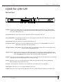
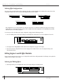
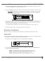
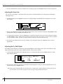
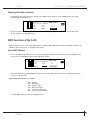
Dual-Engine Multi-Effects Processor
User’s Guide
Please visit Digitech Studio on the World Wide Web at http://www.digitech.com
WARNING
CAUTION
FOR YOUR PROTECTION, PLEASE READ THE FOLLOWING:
RISK OF ELECTRIC SHOCK
DO NOT OPEN
A T T E N T I O N : RISQUE DE CHOC ELECTRIQUE - NE PAS OUVRIR
W A R N I N G : TO REDUCE THE RISK OF FIRE OR ELECTRIC
SHOCK DO NOT EXPOSE THIS EQUIPMENT TO RAIN OR MOISTURE
The symbols shown above are internationally accepted symbols that warn of potential
hazards with electrical products.The lightning flash with arrowpoint in an equilateral
triangle means that there are dangerous voltages present within the unit.The
exclamation point in an equilateral triangle indicates that it is necessary for the user to
refer to the owner’s manual.
These symbols warn that there are no user serviceable parts inside the unit. Do not
open the unit. Do not attempt to service the unit yourself. Refer all servicing to
qualified personnel. Opening the chassis for any reason will void the manufacturer’s
warranty. Do not get the unit wet. If liquid is spilled on the unit, shut it off immediately
and take it to a dealer for service. Disconnect the unit during storms to prevent
damage.
WATER AND MOISTURE: Appliance should not be used near water (e.g. near a bathtub,
washbowl, kitchen sink, laundry tub, in a wet basement, or near a swimming pool, etc). Care
should be taken so that objects do not fall and liquids are not spilled into the enclosure
through openings.
POWER SOURCES: The appliance should be connected to a power supply only of the
type described in the operating instructions or as marked on the appliance.
GROUNDING OR POLARIZATION: Precautions should be taken so that the grounding
or polarization means of an appliance is not defeated.
POWER CORD PROTECTION: Power supply cords should be routed so that they are
not likely to be walked on or pinched by items placed upon or against them, paying particular
attention to cords at plugs, convenience receptacles, and the point where they exit from the
appliance.
SERVICING: To reduce the risk of fire or electric shock, the user should not attempt to
service the appliance beyond that described in the operating instructions. All other servicing
should be referred to qualified service personnel.
FOR UNITS EQUIPPED WITH EXTERNALLY ACCESSIBLE FUSE
RECEPTACLE: Replace fuse with same type and rating only.
U.K. MAINS PLUG WARNING
ELECTROMAGNETIC COMPATIBILITY
A moulded mains plug that has been cut off from the cord is unsafe. Discard the mains
plug at a suitable disposal facility. NEVER UNDER ANY CIRCUMSTANCES
SHOULD YOU INSERT A DAMAGED OR CUT MAINS PLUG INTO A 13
AMP POWER SOCKET. Do not use the mains plug without the fuse cover in place.
Replacement fuse covers can be obtained from your local retailer. Replacement fuses
are 13 amps and MUST be ASTA approved to BS1362.
This unit conforms to the Product Specifications noted on the Declaration of
Conformity. Operation is subject to the following two conditions:
• this device may not cause harmful interference, and
• this device must accept any interference received, including interference that
may cause undesired operation. Operation of this unit within significant electromagnetic fields should be avoided.
• use only shielded interconnecting cables.
SAFETY INSTRUCTIONS
NOTICE FOR CUSTOMERS IF YOUR UNIT IS EQUIPPED WITH A
POWER CORD.
WARNING: THIS APPLIANCE MUST BE EARTHED.
The cores in the mains lead are coloured in accordance with the following code:
GREEN and YELLOW - Earth
BLUE - Neutral
BROWN - Live
As colours of the cores in the mains lead of this appliance may not correspond with
the coloured markings identifying the terminals in your plug, proceed as follows:
• The core which is coloured green and yellow must be connected to the
terminal in the plug marked with the letter E, or with the earth symbol, or
coloured green, or green and yellow.
• The core which is coloured blue must be connected to the terminal marked N
or coloured black.
• The core which is coloured brown must be connected to the terminal marked
L or coloured red.
This equipment may require the use of a different line cord, attachment plug, or both,
depending on the available power source at installation. If the attachment plug needs
to be changed, refer servicing to qualified service personnel who should refer to the
table below. The green/yellow wire shall be connected directly to the unit's chassis.
CONDUCTOR
WIRE COLOR
L
Line
Brown
Black
N
Neutral
Blue
White
Earth Grnd.
Green/Yel.
Green
WARNING: If the ground is defeated, certain fault conditions in the unit or in the
system to which it is connected can result in full line voltage between chassis and
earth ground. Severe injury or death can then result if the chassis and earth ground are
touched simultaneously.
S-200
DECLARATION OF CONFORMITY
Manufacturer’s Name:
Manufacturer’s Address:
declares that the product:
Product Name:
Product Options:
Digitech Studio
8760 S. Sandy Parkway
Sandy, Utah 84070, USA
S-200
All
conforms to the following Product Specifications:
Safety:
EN 60065 (1993)
IEC 65 (1985) with Amendments 1, 2 & 3
EMC:
EN 55013 (1990)
EN 55020 (1991)
Supplementary Information:
The product herewith complies with the requirements of the Low Voltage Directive 73/23/EEC and EMC
Directive 89/336/EEC as amended by Directive 93/68/EEC.
Digitech Studio
President of Digitech Studio
8760 S. Sandy Parkway
Sandy, Utah 84070, USA
Tel: 801.566.8800
Fax: 801.566.7005
Effective May 1, 1998
European Contact: Your Local Digitech Studio Sales and Service Office or
International Sales Office
3 Overlook Drive #4
Amherst, New Hampshire 03031, USA
Tel: 603.672.4244
Fax: 603.672.4246
User Guide
I
S-200
Table of Contents
Safety Information
Declaration of Conformity................................................................I
Table of Contents ............................................................................II
Section 1 - Introduction
Congratulations............................................................................1
Included Items ............................................................................1
S-200 Features ..............................................................................1
Warranty ......................................................................................2
A Quick Tour of the S-200 ............................................................3
The Front Panel............................................................................3
The Rear Panel..............................................................................4
Section 2 - Operation and Editing
Program Mode ............................................................................5
Naming Program Storing Changes ..............................................5
Selecting Effect Configurations ..................................................6
Editing Engine A and B Engines ..................................................6
Selecting and Editing Effects ......................................................6
EQ and Noise Gate Adjustments..................................................7
Adjusting the Dry Path Defeat ....................................................8
Adjusting the Display Contrast ....................................................9
MIDI Functions ............................................................................9
MIDI Channel Selection ..............................................................9
MIDI CC Command Information ................................................10
Section 3 - Effects and Parameters
Modulation Effects ......................................................................11
Pitch Shifters ................................................................................12
Delay ............................................................................................12
Reverb ..........................................................................................13
Other Effects (Vocoder, Ring Modulator, Compressor
and De-Esser) ..............................................................................14
Section 4 - Appendix
Resetting the S-200 ......................................................................15
Footswitch Set-Up ......................................................................16
Specifications................................................................................17
Program List ................................................................................18
II
User Guide
S-200
Section -1 Introduction
Section-1 Introduction
Congratulations...
... you are now the owner of a Digitech Studio S-200 multi-effects processor. The S-200 offers you Dual-Engine processing with Stereo input and
output routings. The S-200 offers a full palette of Studio digital effects that can accommodate any studio or live situation, making the S-200 a true
power plant effects processor.
This User’s Guide is your key to understanding the powerful world of the S-200. Read it carefully. After you've had time to familiarize yourself with the
unit, feel free to utilize the S-200 to its full processing potential. Good luck, and thank you for choosing Digitech Studio.
Your S-200 was carefully assembled and packaged at the factory. Before you proceed any further, make sure the following items are included:
• (1) S-200 User’s Guide
• (1) Digitech Studio S-200 Dual Engine Multi-Effects processor
• (1)Power Cord
• (1) Digitech Studio warranty card
Please save all packing materials. They were designed to protect the unit from damage during shipping. In the unlikely event that the unit requires
service, use only the factory supplied carton to return the unit.
S-200 Features:
• Stereo Inputs and Outputs
• 5 Effect Routing Configurations
• Dual-Engine Processing
• Studio Reverbs and Modulation Effects
• Large Custom Display
• 20 bit A/D and D/A Converters
• 24-bit signal path, 48-bit internal data path
• MIDI Program Change and CC Commands
• 96 dB signal to noise ratio
• Footswitch Control
• Vocoder Effect Module
• Compressor and De-Esser Effects
User Guide
1
Section -1 Introduction
S-200
Warranty
We at Digitech
Studio are very proud of our products and back-up each one we sell with the following warranty:
1. The warranty registration card must be mailed within ten days after purchase date to validate this warranty.
2. Digitech Studio warrants this product, when used solely within the U.S., to be free from defects in materials and workmanship under
normal use and service.
3. Digitech Studio liability under this warranty is limited to repairing or replacing defective materials that show evidence of defect,
provided the product is returned to Digitech Studio WITH RETURN AUTHORIZATION, where all parts and labor will be covered up to a
period of one year. A Return Authorization number may be obtained from Digitech Studio by telephone. The company shall not be liable
for any consequential damage as a result of the product's use in any circuit or assembly.
4. Proof-of-purchase is considered to be the burden of the consumer.
5. Digitech Studio reserves the right to make changes in design, or make additions to, or improvements upon this product without
incurring any obligation to install the same on products previously manufactured.
6. The consumer forfeits the benefits of this warranty if the product's main assembly is opened and tampered with by anyone other than a
certified Digitech Studio technician or, if the product is used with AC voltages outside of the range suggested by the
manufacturer.
7. The foregoing is in lieu of all other warranties, expressed or implied, and Digitech Studio neither assumes nor authorizes any person to
assume any obligation or liability in connection with the sale of this product. In no event shall Digitech Studio or its dealers be liable
for special or consequential damages or from any delay in the performance of this warranty due to causes beyond their control.
DigiTech Studio™ and S-200™ are registered trademarks of the Harman Music Group Incorporated.
NOTE: The information contained in this manual is subject to change at any time without notification. Some information contained in this
manual may also be inaccurate due to undocumented changes in the product or operating system since this version of the manual was
completed. The information contained in this version of the owner's manual supersedes all previous versions.
2
User Guide
S-200
Section -1 Introduction
A Quick Tour of the S-200
The Front Panel
2
1
Stereo Large Hall
L
R ng
4
5
eq
6 a-d
Hall
L
R
7
3
FACT
USER
UTIL
EDIT
CHNG
LINK
MIDI
8
9 10 11 12
1) Display - This large custom display is where you receive information for programming and operation of the S-200. This information
includes: effect types and parameters and all Utility mode functions including Contrast, Dry level, MIDI program information,
Factory Reset and Footswitch set-up.
2) Program Descriptions - This list tells you the factory program list of all Factory 99 programs in the S-200.
3) Program/Data Wheel - In Program mode, this wheel is used to change programs and when the unit is in Edit mode it is used to select
effects and change parameters.
4) Program Button -This button returns the S-200 to program mode when pressed.
5) Configuration Button - This button is used to select Configuration mode. Once pressed, use the <Program/Data> wheel to select a
different effect configuration for the selected program.
6 a-d) Effect Parameter Editing Buttons - These four buttons allow you to do all parameter editing of effects in Edit and Utility modes in
conjunction with the <Program/Data> wheel.
7) Engine A/B Select - This button selects the Engine A and B effect engine modules. Successive presses of this button will toggle between
Engines A/B in effect configurations 2-5. Once this button is pressed and the Engine effect module has been selected,
use the <Program/Data> wheel to select the effect to be used in this effect engine module.
8) EQ/Gate - This button (in conjunction with the four parameter buttons) are used to adjust the three band EQ and Noise gate threshold and
release. Press once to select the EQ and press twice to select the Noise Gate.
9) Utility - This button is used to access all Utility mode functions including: Dry signal path On and Off, selecting the MIDI channel,
adjusting the display contrast and footswitch set-up.
10) Preview - This button produces a brief reference tone to audition effect sounds without the use of an input signal.
11) Store Button - This button is used to store program modifications in the S-200.
12) Bypass - This button is used to Bypass all of the digital effects in the S-200 and allow the original dry signal to pass through the S-200.
User Guide
3
S-200
Section 1 Introduction
The Rear Panel
1
2
3
4
5
6
7
8
1) Input Level- This knob controls the level of signal entering the S-200. For optimal performance, set this level so the Input level indicators
(located on the front panel) occasionally peak the bargraph.
2) Left/Mono Input - This Input jack is used for the Left or Mono input. When only the Left input jack is used, the signal is sent to both Left
and Right S-200 inputs.
3) Right Input - This is the Right Input jack for the S-200 that when used with Left input will preserve stereo imaging.
4) Left/Mono Output - This is the S-200’s left audio output. This output must be used if a mono effect is desired.
5) Right Output - This is the S-200’s right audio output. Use both left and right outputs to take advantage of stereo effects.
6 Footswitch Jack - This jack is used for the insertion of the Digitech FS-300 footswitch that will control multiple functions of the S-200.
7) MIDI - This MIDI jack is used for receiving MIDI program change and CC information.
8) AC Line Input - This is the AC power receptacle. Please use only the supplied power cord.
4
User Guide
S-200
Section -2 Operation and Editing
Section-2 Operation and Editing
This section will provide you with all of the information necessary to help optimize the digital signal processing power of the S-200.
Program Mode
When the S-200 is in Program mode, you can move from one program to the next by either using the <Program/Data> wheel, the optional
Digitech FS-300 footswitch or incoming MIDI program change commands from another device such as a sequencer or keyboard. Upon powerup, the S-200 display will appear something like this:
Stereo Large Hall
L
R ng eq
Hall
L
R
FACT
USER
UTIL
EDIT
CHNG
LINK
MIDI
When the S-200 is in any other mode and you wish to abort and return to program mode, simply press the <Program> button.
Naming Programs and Storing Changes
1. Anytime a program has been modified, the CHNG icon in the display will appear, indicating that the currently selected program has
been modified. To name and store changes: press the <Store> button once. The display will now appear something like this,
prompting you to re-name the program:
EdIT NAME THEN PRESS STORE
Stereo Large Hall
≥
del
≥
ins
FACT
USER
UTIL
EDIT
CHNG
LINK
MIDI
2. At this point, if you wish to change the program name, you can use the parameter <1> button to delete character spaces. The <2> and
<3> buttons to select the character position. The <4> button is used to insert character spaces and the <Program/Data> wheel to
change characters.
3. Once the desired name is in place, press the <Store> button again and the display will now appear like this:
Store program
to user: 1
Stereo Large Hall
FACT
USER
UTIL
EDIT
CHNG
LINK
MIDI
4. Now use the <Data/Program> wheel to select the desired User program location that you wish to store the program to. Once the
location has been chosen, press the <Store> button again and the display will briefly read:
***STORING***
***PROGRAM***
5. You will now be returned to Program mode.
User Guide
5
S-200
Section -2 Operation and Editing
Selecting Effect Configurations
The S-200 provides you with five different effect configurations that allow you ultimate flexibility and versatility in effect routing. The five effect
configurations available in the S-200 are located in the Configuration menu and are as follows:
Configuration 1
L
eq
R ng
studio
Configuration 2
L
eq CHORUS
R ng
L
R
hall
L
R
Configuration 3
L
eq
R ng
chorus
hall
Stereo Inputs and Outputs (Series Effects)
Stereo Inputs and Outputs
L
R
Stereo Inputs and Outputs (Parallel Effects)
Configuration 4
L
ng eq chorus
hall
R ng eq
Configuration 5
L ng
chorus
eq
L
R
R ng
Dual Mono Inputs and Outputs (Parallel Effects)
eq
L
R
hall
Dual Mono Inputs and Stereo Outputs (Parallel Effects)
Effect Configuration 1 uses one effect module because both processing engines are combined for maximum processing power. This larger
module allows you to have longer delay times and more dense sounding reverbs. Effect configurations 2-5 use Dual-Engine effect modules
which allow you to use two effects per program.
To select any one of these five different effect engine configurations, simply perform the following procedure:
1. Press the <Config> button and the display will appear something like this, indicating that you are in the configuration select mode.
Configuration 1
L
R ng
eq
FACT
USER
UTIL
EDIT
CHNG
LINK
MIDI
L
R
Hall
2. Now simply turn the <Program/Data> wheel until the desired configuration (1-5) appears in the display.
3. Once the desired effect configuration has been selected, simply press the <Store> button to store the configuration change at the
desired program location.
Editing Engine A and B Effect Modules
Because of its processing power, the S-200 gives you two Engine Effect modules that are fully programmable. The following section explains the
simple procedure for Engine A and B editing.
Selecting and Editing Effects
1. From Program mode, press the <Engine A/B> button and the display will appear something like this:
L
R ng eq
PREdLY
6
dECAY
HALL
dAMP
LEVEL
L
R
FACT
USER
UTIL
EDIT
CHNG
LINK
MIDI
User Guide
S-200
Section - 2 Operation and Editing
Note- Dual Engine effect configurations are used in configurations 2-5. If a dual-engine effect configuration is currently in use, successive
presses of the <Engine A/B> button will toggle between Engines A and B.
2. Now turn the <Program/Data> wheel to select the effect to be used. The selected effect’s name will change as new effects are selected.
• EFFECT PREVIEW At this point, the S-200 has a <Preview> button that will allow you to instantly hear any one of the effects
in the S-200. When you have an effect that you wish to audition, press the <Preview> button and the S-200 will play a brief
sample and the display will appear as follows:
L
R eq ng
PREdLY
dECAY
HALL
dAMP
L
R
LEVEL
FACT
USER
UTIL
EDIT
CHNG
LINK
MIDI
3. Once the effect to be used has been selected, you can use the <Parameter 1-4> edit buttons (Which are located directly below the corresponding available parameters names) to select and modify the parameters of the selected effect by pressing the desired parameter
button and then turning the <Program/Data> wheel to change the parameter values.
For a complete list of the Effects available in the S-200 and their respective parameters, please see Section 3 on pages 11-14.
4. Once all of the edits have been made to the selected program, make sure to store any changes.
EQ and Noise Gate Adjustments
This editing function allows you to make EQ and Noise Gate modifications to each program. The procedure for both is as follows:
Adjusting the EQ
The S-200 offers a three band EQ with Low Shelf (200Hz) EQ Frequency, Parametric Frequency, Parametric Level and Hi Shelf (3 kHz) EQ
Frequency parameters. To adjust any one of these four, perform the following procedure:
1. From Program mode, press the <EQ/Gate> button once and the display will appear something like this:
12DB
eq
-12DB
0DB
1.0khz
0DB
0DB
FACT
USER
UTIL
EDIT
CHNG
LINK
MIDI
2. Now to make adjustments to the four different EQ parameters use the <Parameter 1-4> buttons and the <Program/Data> wheel.
Parameter and value range for each is listed below.
Parameter 1 - Low Shelf EQ Frequency (200Hz) - Range for the Low EQ is from -12 to +12 dB.
Parameter 2 - Parametric Frequency - Range for the Parametric Frequency is from 25Hz to 20.0Khz.
Parameter 3 - Parametric Level - Range for the Parametric Level is from -12 to +12 dB.
Parameter 4 - High Shelf EQ Frequency (3kHz) - Range for the High EQ is from -12 to +12 dB.
User Guide
7
S-200
Section -2 Operation and Editing
3. Once the modifications have been made, remember to store any changes and press the <Program> button to return to Program mode.
Adjusting the Noise Gate
The S-200 gives you the ability to custom tailor the Noise gate parameters (Threshold and Release) for each program by performing the
following procedure:
1. From Program mode, press the <EQ/Gate> button twice. The display will appear something like this, indicating that you are in Noise
Gate edit mode:
0DB
N.gate
-50dB
THRESH
10
RELEASE
FACT
USER
UTIL
EDIT
CHNG
LINK
MIDI
2. Now press the <Parameter 1> button and Threshold parameter becomes active for adjustment by turning the <Program/Data> wheel.
The range for the Noise gate Threshold is from: Off, -99 to 0 dB.
3. To adjust the Noise Gate Release , press the <Parameter 2 > and the Release parameter now becomes active for adjustment by turning
the <Program/Data> wheel to adjust the Noise Gate Release parameter. Release time range is from 1 to 10. Release times are as follows:
1). 10ms, 2).100ms 3).200ms 4). 300ms 5). 400ms 6). 500ms 7). 600ms 8). 700ms 9). 800ms 10). 900ms.
4. Once all Noise gate modifications have been made, remember to store the changes and press the <Program> button to return to
program mode.
Adjusting the Dry Path Defeat
This editing procedure will allow you to globally turn a Dry signal path Off for use with a mixing consoles' effects sends or On for use with
single instrument input signals (such as guitar, saxophone and others). The procedure is as follows:
1. To defeat the Dry signal within the effect configuration of the S-200 (turning it On or Off), press the <Utility> button once and the
display will appear like this:
Utility Menu page 1 0f 4
11
ON
CH1
dry
MIdI
contrast
FACT
USER
UTIL
EDIT
CHNG
LINK
MIDI
2. This now indicates that the Dry signal has been turned Off in individual programs, creating a 100% Wet signal globally in the S-200. To
exit this mode, press the <Program> button.
Note: The Dry path will automatically be turned off when either a Tremolo, Panner, Vocoder, Compressor, Rotary Speaker, Reverse
Reverb or De-Esser effect is used in a program, since the dry signal is already included in these effects.
8
User Guide
S-200
Section - 2 Operation and Editing
Adjusting the Display Contrast
1. To adjust the display contrast in the S-200, simply press the <Utility> button and then press the <Parameter 4> button and the
display will appear something like this:
Utility Menu
ON
Ch1
dry
MIdI
page 1 of 3
11
Contrast
FACT
USER
UTIL
EDIT
CHNG
LINK
MIDI
2. At this point, simply turn the <Program/Data> wheel to select the desired display contrast. To exit this or any other utility mode
function, simply press the <Program> button.
MIDI Functions of the S-200
Within the Utility menu of the S-200, several MIDI functions are available including: MIDI Channel selection and MIDI CC Commands. The
following, will show you how to access and optimize these features.
Select MIDI Channel
1. To select the MIDI channel in which the S-200 receives program change information, from Program mode, press the <Utility> button
and then press the <Parameter 2> and the display will appear as follows:
Utility Menu
ON
Ch1
dry
MIdI
page 1 of 3
11
Contrast
FACT
USER
UTIL
EDIT
CHNG
LINK
MIDI
2. At this point, simply turn the <Program/Data> wheel to select the desired MIDI channel. The options for the MIDI channel selection
ranges from: 1-16, ALLand Off.
MIDI program change numbers are as follows:
1-99 = Programs
100 = Effects Bypass
101 = Exit Effects Bypass
102 = Effect Bypass Toggle
103 = Selects User Program Bank
104 = Selects Factory Program Bank
3. To exit the MIDI channel menu, press the <Program> button.
User Guide
9
S-200
Section - 2 Operation and Editing
MIDI CC Information
The S-200 will also receive MIDI CC information for parameter control of the following parameters:
Engine A
Parameter 1 - CC 16
Parameter 2 - CC 17
Parameter 3 - CC 18
Parameter 4 - CC 19
Engine B
Parameter 1 - CC 20
Parameter 2 - CC 21
Parameter 3 - CC 22
Parameter 4 - CC 23
EQ
Low Shelf - CC 24
Frequency - CC 25
Frequency Level - CC 26
High Shelf - CC 27
Noise Gate
Threshold - CC 28
Release - CC 29
Dry Level - On/Off - CC 7
10
User Guide
S-200
Section - 3 Effects and Parameters
Section - 3 Effects and Parameters
This section provides you with a detailed description of the Digital effects available in the S-200 and their parameters and values.
Modulation Effects
Effect Name
Parameter 1
Parameter 2
Parameter 3
Parameter 4
Chorus
Speed Depth
Delay
Level
Flange
Speed
Depth
Feedback
Level
Phaser
Speed
Depth
Feedback
Level
Tremolo
Speed Depth
N/A
Level
Panner
Speed
Depth
N/A
Level
Speed
Type
X-over Freq
Level
Rotary Speaker
The Modulation effects menu offers a vast list of modulating effects ranging from Chorus to a Rotary Speaker simulator. These modulation
effects are ideal for producing lush sounding effects that can add dimension to any signal. The parameters and values for the modulation
effects are as follows:
Speed
The Speed parameter controls the speed of the Modulation in the effect. Range is from 0 to 99 or Slow
to Fast.
Depth
This parameter controls the amount of depth of the Modulation effect. Range is from 0 to 99.
Delay
This parameter controls the delay time within the Chorus effect. Range is from 0 to 40 milliseconds.
Feedback
This parameter controls the amount of regeneration feedback in the Flange and Phaser effects. Range is
from 0 to 99%.
Type
This parameter selects between six various Rotary Speaker Simulator settings. Odd numbered types are
Brake (no Rotor movement) To Fast with 3 different speed and depth combinations. Even numbered
types are slow to fast with 3 different speed and depth combinations.
Cross-over Frequency
This parameter selects the frequency where the signal is split between the Rotor and the Horn. Range is
from 100 to 800 Hz.
Level
This parameter allows you to set the overall level of the selected effect. Range is from 0 to 100.
User Guide
11
S-200
Section - 3 Effects and Parameters
Pitch Shifters
Effect Name
Pitch Shift
Detuner
Parameter 1
Shift Detune Amt
Parameter 2
Parameter 3
Parameter 4
Tracking
N/A
Level
N/A
N/A
Level
The Pitch Shifting effects menu includes a Pitch Shifting effect that allows you to shift the original signal to help produce Harmony effects,
while the Detuner effect will help you thicken up any signal to add dimension to your sound. Parameters for the Pitch Shifting Effects are as
follows:
Shift
This parameter sets how far the signal is shifted. Range is from -24 to +24 semi-tones.
Tracking
This lets you select the tracking of the Pitch shifter effects. Range is from 1 to 3.
Detune Amount
This parameter sets the amount of Detune in the effect. Range is from -24 to +12 cents.
Level
This parameter sets the overall level of the Pitch shifter effect. Range is from 0 to 100.
Level
This parameter allows you to set the overall level of the selected effect. Range is from 0 to 99.
Delay
Effect Name
Parameter 1
Parameter 2
Parameter 3
Parameter 4
Mono Delay
Delay Coarse
Delay Fine
Feedback
Level
Stereo Delay
Delay Coarse
Delay Fine
Feedback
Level
2-Tap
Delay Coarse
Delay Fine
Feedback
Level
Echo
N/A
Repeats
Level
Karaoke
The S-200 offers three different Delay effects including: Mono, Stereo and 2-Tap, offering the ultimate flexibility in digital delay applications.
The S-200 also offers a Karaoke delay effect. The parameters and their values are as follows:
Note: When Delay effects are used in Effect Configuration 1 (which is a Combined Engine effect module), longer delay times are
available. These Delay time differences are marked C (Combined) and S(Single) in the Maximum delay time chart which
follows.
Maximum Delay times
D-1 Mono (Single =1000 milliseconds and Combined=2000 milliseconds)
D-2 Stereo (Single =700 milliseconds and Combined =1000 milliseconds)
D-3 2-Tap (Single=1000 milliseconds and Combined=2000 milliseconds)
Delay Coarse
12
This parameter controls the length of the Delay Coarse time Range is from 100 milliseconds to 2
seconds).
User Guide
S-200
Section - 3 Effects and Parameters
Delay Fine
This parameter controls the length of the Delay Fine time. Range is from 0 to 99 milliseconds.
Echo
This parameter controls the length of the Echo that is offered in the Karaoke. Echo settings are 1-5.
Feedback
This parameter controls the amount of delay repeats in the delay effect. Range is from 0 to 99% and
repeat-hold.
Repeat
This parameter controls the number of delay repeats in the D-4 Karaoke effect. Range is from 1 to 10.
Level
This parameter allows you to set the overall level of the selected effect. Range is from 0 to 100.
Reverb
Parameter 1
Parameter 2
Parameter 3
Parameter 4
Stage
Predelay
Decay
Damping
Level
Room
Predelay
Decay
Damping
Level
Hall
Decay
Damping
Level
Plate
Predelay
Predelay
Decay
Damping
Level
Chamber
Predelay
Decay
Damping
Level
Cathedral
Predelay
Decay
Damping
Level
Arena
Predelay
Decay
Damping
Level
Gated
Predelay
Decay
Diffusion
Level
Reverse
Predelay
Decay
Diffusion
Level
Effect Name
Reverb is the perfect effect for adding dimension to any recording or live application where you need to emulate the size and shapes of
different types of rooms. The following explains the parameters that are available in the Reverb effects.
Note: When Reverb is used in Effect Configuration 1 (Whole effect module) larger and denser sounding Reverbs can be attained.
Pre Delay
Controls the length of time before the reverb reflections are heard. Range is from 0 to 99 ms.
Decay
This parameter controls the decay length (reverb time) of the reverberation. Range is from 1 to 10.
Damping
This parameter controls the high frequency decay of the reverb effect and ranges from 1 to 10.
Diffusion
This parameter controls the reverb smoothness and ranges from 1 to 10.
Level
This parameter allows you to set the overall level of the selected effect. Range is from 0 to 100.
User Guide
13
S-200
Section - 3 Effects and Parameters
Other Effects
Parameter 1
Parameter 2
Parameter 3
Parameter 4
Ring Modulator
Frequency
N/A
N/A
Level
Compressor
Threshold
Ratio
Attack
Gain
Vocoder
Sibliance
Source
Type
Level
De-Esser
Threshold
Ratio
Attack
Gain
Effect Name
The S-200 also offers an additional menu of hard to find effects including: a 16-band Vocoder which takes a vocal signal (using the Left input)
and superimposes it onto another input signal such as a keyboard or the built-in Tone Generator (using the Right input) to produce a vocal
effect that sounds more robotic than human. This menu also provides you with a Ring modulator that can produce mathematically-based
harmonic effects. Also included is a state-of-the-art Compressor that is ideal for making any signal stand out with the right amount of
compression. A special De-Esser is also included to fine-tune vocal tracks. The parameters for these effects are as follows:
14
Frequency
This parameter sets the modulation frequency of the Ring Modulator effect. The Frequency range is from
300Hz to 1500Hz.
Threshold
This parameter sets the level at which Compression (or De-Essing) begins. Range is -60 dB to 0 dB.
Ratio
This parameter sets the ratio of Compression (or De-Essing). Range is from 1:1 to ∞:1.
Attack
This parameter controls the attack time of the Compressor or De-Esser. Range is from 0.1 ms to 15 ms.
Gain
This parameter allows you to set the overall gain of the selected effect. Range is from -19dB to 20dB.
Sibilance
This parameter allows you to set the amount of Vocal High Frequency that is passed through the Vocoder
effect. Range is from 0 to 100.
Source
This parameter allows you to select an internal tonal frequency reference generator or external
(Keyboard) source for which the Vocal input will be routed through. Range is from: Instrument Input, or
20Hz to 600Hz (Tone Generator).
Type
This parameter allows you to select different settings of the Vocoder in the S-200. These settings vary in
the placement of the frequency bands. There are five different type settings in this parameter.
Level
This parameter allows you to set the overall level of the selected effect. Range is from 0 to 100.
User Guide
S-200
Section - 4 Appendix
Section - 4 Appendix
This section provides you with information to Factory Reset the S-200, Foot switch menu set-up, Specification page and a Program list
Resetting the S-200
The following Factory reset procedures all you to reset the S-200 from Utility menu or from power up.
Warning- All User program information will be deleted when the reset is performed
Utility Menu Factory Reset
1. From Program mode, press the <Utility> button three times until you reach page three and the display will appear something like this:
Utility Menu
page 3 of 3
factory reset
FACT
USER
UTIL
EDIT
CHNG
LINK
MIDI
2. To proceed with the reset, press the <Param 2> and the display will now read: ARE YOU SURE ?
3. If you wish to reset, press the <Param 4> button and the S-200 will proceed to reset. If you wish to abort, press the <Param 3>
button and press the <Program> button to return to Program mode.
Power Up Reset
1. To perform a factory reset from power up on the S-200, simply press and hold the <Program> button while applying power to the
unit. An asterisk will appear in the top line of the display and will appear like this:
**
2. Now release the <Program> button and immediately press the <Config> button and the S-200 will proceed to reset. In the process of
resetting, the S-200 will briefly display the current software version number and then return to Program mode.
Footswitch Set-Up Menu
The S-200 allows you to custom configure the footswitch menu for use with the Digitech FS-300 footswitch to perform numerous functions
such as:
Program Up
Rotary Speaker On/Off
User Guide
Program Down
Delay Time Tap
Bypass
Repeat Hold
15
S-200
Section - 4 Appendix
The procedure for setting up the footswitch assignment is as follows:
1. From Program mode, press the <Utility> button twice until you reach page 2 and the display will appear something like this:
Utility Menu page 2 of 3
PgmUp
PgmDn Bypass
foot sw: a
b
c
FACT
USER
UTIL
EDIT
CHNG
LINK
MIDI
2. To make function assignments to any one of the three footswitches on the FS-300, press the <Param 2> button for switch A, press the
<Param 3> button for switch B and press <Param 4> to select switch C.
3. Once the desired footswitch has been selected, use the <Program/Data> wheel to scroll through the available footswitch function
options available for each switch.
4. Once the footswitch assignments have been made, notice that these assignments function the same in all programs globally and can be
changed at anytime.
5. To exit this menu, press the <Program> button and you will be returned to program mode.
16
User Guide
S-200
Section - 4 Appendix
Specifications
Frequency Response:
20-20kHz +/-0.5dB
Signal-to-Noise Ratio:
96dB (A-Weighted ref=Max signal 22kHz measurement bandwidth)
THD:
Less than 0.008%
Memory Allocations:
99 User - 99 Factory Programs
Sampling Rate:
46.875kHz
A/D Converter:
20 bit, 128 oversampled
D/A Converter:
20 bit, 128 oversampled
Internal Signal Path Width:
24 bits
Multiplier Size:
24 bits x 24 bits
Inputs:
Stereo (2) 1/4” Unbalanced - Max In + 18 dBu
Outputs:
Stereo (2) 1/4” Impedance Balanced - Max + 18 dBu
MIDI:
MIDI In Program Changes, Program Dump and MIDI CCs
Power Consumption:
10 watts
Power Requirements:
Internal
Net Weight:
4.2lbs (1.91kg)
User Guide
17
S-200
Section - 4 Appendix
Program List
The following is a list of all the factory Programs in the S-200
Showcase
1
2
3
4
5
6
7
8
9
10
Stereo Large Hall
Deep Phaser and Delay
Deep Chorus and Reverb Parallel
Gold Foil Plate
Octave Down Pitch & Parallel Detune
4 Voice Chorus
Karaoke VIP
Panning Detune
Deep Space
Ballad Delay Verb
Reverbs
11
12
13
14
15
16
17
18
19
20
21
22
23
24
25
26
27
28
29
30
Warm Hall
Motion Hall
Open Arena
Concert Stadium
Gliss Sizzle Verb
Cathedral
Vocal Plate
Small Bright Room
Bright Chamber
Wood Studio
Thick Studio
Studio Vocal Rev/Dly
Warm Chamber
Percussion Plate
Gated Drum in Room
Opera Hall
250ms Gated Reverb
500ms Gated Reverb
500ms Reverse Reverb
Squashed Plate
Modulation
31
32
33
34
35
36
37
38
39
40
41
42
43
44
45
Light Chorus
Deep Chorus
4 Voice Chorus
Vibrato Chorus
Medium Flange
Deep Flange
Medium Phaser
Deep Phaser
Deep Slow Tremolo
Fast Shallow Tremolo
Slow Wide Panner
Rotary Slow to Fast
Rotary Stop to Fast
Mild Detune
Heavy Detune
Delay / Karaoke
46
47
48
49
50
18
1 Second Ping-Pong
Doubling Delay
Stereo 250ms Echo
Stereo 500ms Echo
500ms 2-Tap Delay
51
52
53
54
55
56
57
58
59
60
Stereo 1 Second Delay
120 bpm 1/4 Note
150 bpm 1/4 Note
200 bpm 1/4 note
Karaoke Room
Panning Delay
Live Vocal Delay
2 Second Delay Loop
Tape Delay
KTV Lounge
Instrumental
61
62
63
64
65
66
67
68
69
70
Guitar - SlapBack
Guitar - Jazz Club
Sax - Sultry Hall
Organ - RotSpeaker
Drums - HipHopGruv
Drums - Piers Room
Piano - Recital
Piano - New Age
Keys - PhaseStrngs
Keys - Brite Rhodes
Multi-Effects
71
72
73
74
75
76
77
78
79
80
81
82
83
84
85
Pyscho Reverse
Chord Quiver
OctaBass Room
Horn Hit Reverb
Triplet Chorus
Panner and Cathedral
Martian Drum Room
Triplet Reverse
Stretched Vibrato
Detune/Room Reverb
Animated Hall
Honkey Tonk Piano
Compressed HallRvb
Tremolo and Echo
Delayed Reverb
Compressor / Vocoder Effects
86
87
88
89
90
Vocal Compressor
Pop/Slap Bass
Tight Drum Kit
Vocoder with External Source
Vocoder with Internal Tone Generator
Dual Engine Programs
91
92
93
94
95
96
97
98
99
Phaser Left - Pitch Right Split
Delay Left - Gated Reverb Right Summed
2 Tap Room Delay
Short Plate - Hall Right Summed
Panner Left - Compressor Right Summed
Reverse Reverb Left - Ring Modulator Split Right
Slap Delay Left - Room Reverb Right Split
Octave Up Left - Octave Down Right Summed
Fast Phase Left - Arena Reverb Right Split
User Guide
8760 South Sandy Parkway
Sandy, Utah, 84070
Telephone 801.566.8919
FAX 801.566.7005
International Distribution:
3 Overlook Drive, Unit 4
Amherst, New Hampshire 03031 U.S.A.
FAX 603.672.4246
Digitech Studio™ and S-200™are registered trademarks
of the Harman Music Group Incorporated
Copyright © 1998
the Harman Music Group Incorporated
Printed In U.S.A. 5/98
Manufactured in the U.S.A.
S-200 18-2218-A
Please Visit Digitech Studio on the World Wide Web at:
http://www.digitech.com