1
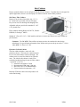
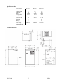
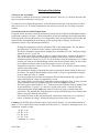
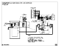
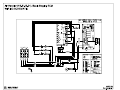
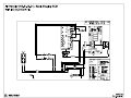
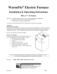
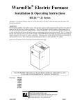
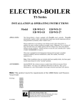
Electric Furnace Installation & Operating Instructions HE-E-**-21 Series Application Special non-WarmFlo, non-heat pump, strip heat elements only, full kW turn-on from stat W input. ECM™ blower speed will have to be setup for full kW rating. Heat/cool conventional roomstat applies. DO NOT DESTROY THIS MANUAL. PLEASE READ CAREFULLY AND KEEP IN A SAFE PLACE FOR FUTURE REFERENCE BY A SERVICE TECHNICIAN. Drawings: NH808 NH809 NS803 EC001 02/14/2006 NI806 Table of Contents Configurator 1 Inlet Cabinets 2 General Comments 3 Application 4 Installation Requirements 6 Mechanical Installation 7 Electrical Installation 10 Setup or Programming 11 Operation Indicators 11 Replacement Parts 13 Drawings Included: NH808 NH809 NS803 EC001 02/14/2006 NI806 Configurator HE-T-KW-CW Type H, A, E, N (see below) Cabinet Width 21 = 21” 24 = 24”* kW Size 10 = 9.6 kW 15 = 14.4 kW 20 = 19.2 kW* 25 = 24 kW* 30 = 28.8 kW* Type All models – ECM™ blower motor, setup selection of four cooling sizes, 50% continuous air (fan – on setting). High efficient air circulation at about 50-watt. H = Full WarmFlo capability with outdoor sensor. This provides warm air outlet temperature dial selection and supply air ramp up with the decrease of outdoor temperature. This WarmFlo feature definitely applies to heat pumps, but it is also the top of the line comfort for straight electric, with air conditioning. The warm air dial suggested setting is 96° or 100° and the front dial selects the rate of ramp up or temperature increase based upon outdoor. The “C” setting will provide 114° warm air at 0° or 125° at -20° F outside. The ECM™ blower also ramps up in speed as there is an increase in supply temperature or decrease in outdoor temperature. Depending upon setup selection, the moderate heating blower speed could be as low as 60% of full capacity and full capacity blower is only used below 30° outdoor. Heat/cool conventional or basic heat pump room thermostat can apply. A = WarmFlo element modulation based upon a front panel set point and duct sensor. Heating blower speed is installation setup per kW size. A higher CFM selection can be made if there is a desire to “work” WarmFlo harder. Heat/cool conventional thermostat applies. E = Non-WarmFlo, 10, 15, or 20 kW built-in strip heat, direct function of roomstat W. Setup selection determines nominal ECM™ motor speed. A thermostat “E” type function could be used to jump to full speed. N = Electric Furnace cabinet only, no electric elements or WarmFlo. This could typically be associated with an inlet hydronics water coil. Control board includes a relay for pump, initiated with input W. Setup selection determines heating blower speed. Cooling speeds and air conditioning interface are the same as mentioned above. Note: Two-speed and multi-function room thermostat can also be configured with this system by adding WF-HP2 interface controller. 02/14/2006 1 NI806 Inlet Cabinets Factory optional cabinets can be configured with this Electric Furnace. Typically these are designed for upflow applications; however, the heat pump coil cabinet could be used in other positions. Side Entry, Filter Cabinet Return air can be ducted into either side, 15-⅜” x 19” cutout hole is provided with one filler plate. Easy access door for checking and changing filter. Adjustable rails are provided for standard 4” x 20” x 20” pleated filter. Filter examples include Honeywell 203721, BestAir HW2020, or Grainger® 6B936. Standard 1” filter (20” x 20”) – field installer could arrive at filter filler bracket for slip-in within the provided rails. Comment – The 3M MERV filter airflow resistance needs to be considered in duct design calculations. Per specification information from 3M the static pressure drop across the 1”, Series 1000, MERV 11 filter is 0.2” SP. Hydronics Coil and Cabinet The inlet cabinet includes a water coil with parameters shown. The return air connection must be on a side which allows coil draw-through. The cabinet can be reversed for either left or right side entry. The inlet for this cabinet is sized for an externally installed packaged return air filter cabinet – typical 20” x 20” size. 1. Nominal or rated Btu/h, 50,000 2. Recommended CFM setup, 1100 min. 3. Inlet water 120° at 10 GPM minimum. 4. Expected outlet air temperature, 115° Reduced CFM and/or inlet water temperature will reduce Btu/h rating. 02/14/2006 2 NI806 General Comments Upflow/Downflow/Horizontal The arrangement of refrigerant coil, hydronics coil, and built-in electric elements need to follow specific air direction or airflow rules, but the orientation of this Electric Furnace is not critical. For upflow and horizontal standard air conditioning applications, the A-coil is mounted at the blower outlet with field provided plenum or manufacturer’s case coil. All models contain GE ECM™ Series 2.3 blower motors. The special Electro Industries interface board allows hookup for heat/cool conventional or basic heat pump room thermostat. Blower speed setup and WarmFlo sensor control are separate for cooling and heating (unique). The ECM™ motor provided in this unit has many features not available in a standard motor. - Improved efficiency - Constant CFM - Soft start and stop - Better humidity control The provided ECM™ motor contains permanently sealed bearings and does not require oiling. Utility Load Control Provisions also included for the Utility Receiver to interrupt compressor and WarmFlo or strip heat. No provisions for dual heat, add EE-5046. Side by Side, with Gas Furnace or Other Dual Heat Arrangements Add-on dual heat controller HP-5046 can simplify the wiring for dual heat. For side by side ducting, a motor operated damper is required to isolate the return air between two blowers. The operation of this motor damper can be controlled from the HP-5046. Installation Setup There are specific peg jumpers relating to cooling tons, heating kW, heat pump reversing valve logic, and thermostat type. These must be properly evaluated and selected to match each installation. The “setup or programming” section has all the detailed instructions and selection tables. The WarmFlo controller also has various dial switch selections relating to duct temperature set point, minimum warm air set point, HP compressor ODT shutoff temperature, and ramp up efficiency dial. These are standard WarmFlo technology and setup requirements, if you’re not familiar with WarmFlo controller study the HD320 WarmFlo information document, also in this package. NOTICE: When changing any setup jumpers, power down and up. ECM™ motor needs 240V power and control power removed to reset and reread specific control lines. Open CB number 1 for 10 seconds. Operation Instructions The “Operation Indicators” section contains information relating to LED monitor lights, thermostat sequences, etc. 02/14/2006 3 NI806 Installation Checkout Attached to this manual is a warranty certification and checkout procedure. This must be completed and returned for warranty coverage. This is the responsibility of the contractor or company which “sold the job” and is assuming responsibility to the end customer. Warranty Statement See the last page of this manual for detailed limited warranty coverage explanation. Application General The configurator, previous page, details several product types. Re-verify nameplate on your received unit to make sure it properly represents the product type you need for your installation/application. The setup control board jumpers provide ECM™ blower motor speed flexibility to match the model and your heat/cool size requirements. This specific model series, HE-E-**-** Special non-WarmFlo, non-heat pump, strip heat elements only, full kW turn-on from stat W input. ECM™ blower speed will have to be setup for full kW rating. 02/14/2006 4 NI806 Specification Chart Model Number Cabinet Width kW rating Btu/h Voltage/Phase Circuit Breaker Amps per CB Source Feed Elements Relays Heat CFM* Max. Temp. Rise Shipping Weight HE-E-10-21 HE-E-15-21 HE-E-20-21 21” 10 34000 240/1 60 42 1 4 2 600 (LO) 45° F 21” 15 51000 240/1 1-60, 1-30 42, 21 2 6 4 900 (M) 45° F 21” 20 68000 240/1 2-60 42, 42 2 8 6 1200 (HI) 45° F Product Dimensions 02/14/2006 5 NI806 Installation Requirements 1. All installation work must be performed by trained, qualified contractors or technicians. Electro Industries, Inc., sponsors installation and service schools to assist the installer. Visit our web site at electromn.com for upcoming service schools. WARNING ALL ELECTRICAL WIRING MUST BE IN ACCORDANCE WITH NATIONAL ELECTRIC CODE AND LOCAL ELECTRIC CODES, ORDINANCES, AND REGULATIONS. WARNING OBSERVE ELECTRIC POLARITY AND WIRING COLORS. FAILURE TO OBSERVE COULD CAUSE ELECTRIC SHOCK AND/OR DAMAGE TO THE EQUIPMENT. CAUTION This unit can only be used for its intended design as described in this manual. Any internal wiring changes, modifications to the circuit board, modifications or bypass of any controls, or installation practices not according to the details of this manual will void the product warranty, the CSA/us certification label, and manufacturer product liability. Electro Industries, Inc., cannot be held responsible for field modifications, incorrect installations, and conditions which may bypass or compromise the built-in safety features and controls. 2. If this is a Dual Heat system, this product relates only to the addition to the furnace ducting system external to the gas or oil force air furnace. The owner/ installer assumes all responsibility and/or liability associated with any needed installation of the gas/oil furnace, fuel system, flue, chimney, etc. Any instructions or comments made within this manual (or factory phone assistance) relating to the gas/oil furnace are provided as comments of assistance and “helps” only. CAUTION This unit shall not be operated (either heating section or blower) until the interior of the structure is completed and cleaned. This also means all duct work must be complete with filter, etc. Both manufacturers’ warranties are void if this unit is operated during structure construction. CAUTION Hazards or unsafe practices could result in property damage, product damage, severe personal injury and/or death. 3. Remember, safety is the installer’s responsibility and the installer must know this product well enough to instruct the end user on its safe use. Safety is a matter of common sense - - a matter of thinking before acting. Professional installers have training and experienced practices for handling electrical, sheet metal, and material handling processes. Use them. 02/14/2006 6 NI806 Mechanical Installation Clearances and Accessibility Zero clearance is allowed on all sides for combustible materials. However, 36” should be allowed at the front for operation, maintenance, and service. To reduce the risk of rusting and appearance, do not install the unit directly on the ground or on a floor that is likely to be wet. In such environments the unit must be elevated by use of a sturdy non-porous material. General Ductwork and Airflow Requirement Design the airflow ductwork to meet the maximum operating airflow (CFM) for the kW and cooling ton requirements (whichever is larger). This document does not provide installation and design information for the ductwork external to this product. It is assumed this is being accomplished by a professional and trained installer understanding ductwork design, airflow/static pressure resistance, and forced air distribution systems. Key requirements information: - - Heating and cooling blower speed or minimum CFM is setup independently. See the “Blower Speed Selection” to match the airflow capacity with the ducting design. The airflow distribution system shall be designed for a maximum of 0.5” SP. Ideally the design should be set at 0.3” to 0.4” SP. The variable speed, ECM™ motor, is sensitive to inlet static pressure. In order for the motor to arrive at the setup CFM (motor RPM adjust according to static pressure) the inlet must have a minimum resistance of about 0.15 to 0.2. If you do not have return air ducting and you’re simply allowing free return air circulation through a filter at this Electric Furnace inlet, you may need to have a slight restriction in order for the blower motor to arrive at its setup speed. All transitions must have a slope of 30° to 45°. There shall be no 90° bends or surfaces causing airflow bounce/eddy current. The manufacturer strongly recommends the return air entering the bottom (under the blower) of the cabinet. For smaller kW and smaller cooling (10 kW or 2-ton) it is permissible to bring the air in on either side of the 32” cabinet. Previous Specification Chart shows the minimum CFM associated with the kW. Again this is setup as detailed in the “Setup or Programming” section. The cooling CFM is also selected but is not shown on the Specification Chart. In many cases the airflow distribution system is probably designed to meet the cooling requirement. The room registers and individual 5” or 6 “ runs must also match the total setup or planned CFM for this installation. Typically a 6” round and a typical room register is rated at 100 CFM. All distribution ducts (supply and return) must be sized for the setup or planned total CFM requirement. The attached duct sizing chart shows various distribution duct sizes relating to their ability to properly handle the stated CFM. Seal connections between this unit and ductwork, all ductwork connections, etc. as required to reduce or eliminate air leakage. Sealing all connections will also reduce air noise. Comment: The ECM™ motor efficiently relates to system static pressure. On one hand a minimum of about 0.2” SP is required for the motor to adjust itself, but above 0.3” it begins to drain high current. For information, consider (at 240): 1.0” SP – 3.4A 0.8” SP – 2.5A 0.5” SP – 0.9A 0.2” SP – 0.4A Continuous Air – 0.25A 02/14/2006 7 NI806 Whether this unit is sitting on or attached to an inlet cabinet, field designed inlet cabinet, or horizontal supports; verify proper support and mechanical strength is provided within the system installation. Rubber isolation pads should be used where possible to reduce sound and vibration transmission. WARNING WHEN HANGING THIS UNIT, THERE MUST BE UNDER SUPPORTS WHICH DISTRIBUTE THE HANGING CHAINS ACROSS THE SURFACE OF THIS UNIT, DO NOT SIMPLY DRILL A HOLE AND USE A COUPLE OF HANGING BOLTS. For information, factory optional inlet cabinets can reduce cost and simplify installation, see previous pages. When installing the unit maintain a minimum clearance of 36” in front of the unit for service accessibility. Upflow, Air Conditioning As stated above, the return air should enter the bottom of this cabinet. Suggest using Electro bottom filter cabinet (page 2) or field constructed equivalent. The A-coil will be mounted above the blower in either a case coil or field constructed plenum. Upflow, Heat Pump In this case the HP refrigerant coil must be at the bottom of the blower in order for WarmFlo to properly add temperature to the heat pump output. Electro inlet cabinet is ideal for using a heat pump A-coil (page 2). This factory available inlet cabinet provides space for standard A-coil and is installed between the filter/inlet cabinet and the Electric Furnace unit itself. The cabinet is designed for 20”H A-coil, but for larger A-coils the top can be above this cabinet approximately 3” (24”). The outlet of the blower will enter into a plenum and directly into distribution duct. Downflow, Air Conditioning Similar to upflow above, the air conditioning coil is positioned at the blower outlet. Depending upon the coil type and drip pan it is positioned in a field constructed plenum as required. A typical packaged 20” x 20” filter cabinet could easily be installed at the blower inlet opening. Downflow, Heat Pump With the WarmFlo elements down and airflow direction down, the A-coil must be at the top of this unit. The factory option Heat Pump Coil Cabinet can be used for coils less than 20” high. This is assuming the heat pump and associated refrigerant coil you are using is designed to drive air “backwards” through the A-coil and drip pan. Use heat pump manufacturer’s recommendation; however, refrigerant coil must be on the inlet side of the elements. 02/14/2006 8 NI806 Horizontal, Air Conditioning Similar to upflow above, the air conditioning coil is positioned at the blower outlet. Depending upon the coil type and drip pan it is positioned in a field constructed plenum as required. As horizontal, the return air would enter the blower end of the cabinet with a typical packaged 20” x 20” filter cabinet. Horizontal, Heat Pump As emphasized above, the heat pump coil must be at the blower inlet. Depending upon the coil physical arrangements and drip pan, it is installed in a field constructed plenum at the blower inlet. Typically a package filter cabinet is installed at the entrance (or ahead of) of the HP coil. The blower outlet goes directly into the distribution duct system. Blower Motor Orientation If the installation is not upflow, the blower motor shall be positioned so the power and control connectors are down. This will prevent water from entering the blower motor through the connector housing opening. Loosen motor mount clamp and rotate motor accordingly. Before tightening motor mount clamp be sure the blower wheel is properly centered inside the blower housing. 02/14/2006 9 NI806 Electrical Installation WARNING TO AVOID THE RISK OF ELECTRIC SHOCK OR DEATH, WIRING TO THE UNIT MUST BE PROPERLY GROUNDED. FAILURE TO PROPERLY GROUND THE UNIT CAN RESULT IN A HAZARD LEADING TO PERSONAL INJURY OR DEATH. Line Voltage The nameplate and/or Installation and Operating Manual specification page provides kW rating and operating current requirements for each specific model. Select the proper wire size to comply with your type of wire routing and NEC field wiring requirements. Field connection is at this product’s furnished circuit breaker. This integrated circuit breaker is a proper local disconnect. WARNING USE ONLY COPPER WIRE FOR CONNECTION TO THE CIRCUIT BREAKER TERMINALS AND INSIDE THIS PRODUCT’S CABINET. If the 240 power service is to be wired as single feed, order option circuit breaker single feed bus bar, part number 5701. WARNING DISCONNECT ALL ELECTRICAL POWER BEFORE ELECTRICALLY CONNECTING OR SERVICING THE UNIT. FAILURE TO DISCONNECT THE ELECTRICAL POWER BEFORE WORKING ON THIS PRODUCT CAN CREATE A HAZARD LEADING TO PERSONAL INJURY OR DEATH. Electric Furnace Control – Inside View, Right Board Room Thermostat, Air Conditioning Use conventional heat/cool, 1H/1C, thermostat. It can be mechanical, digital, power robbing, battery operated, setback, etc. If mechanical, set the heat anticipator to 0.2. Connect the standard R, W, G, Y stat terminals to the control board HEAT/COOL terminal block with the same letters. Room Thermostat, 2-Speed Air Conditioning Use conventional heat/cool, 2H/2C, thermostat. It can be mechanical, digital, power robbing, battery operated, setback, etc. If mechanical, set the heat anticipator to 0.2. Connect the R, W, G stat terminals to the control board HEAT/COOL terminal block with the same letters. Connect the Y1 stat terminal to the control board Y1 tab. Connect the Y2 stat terminal to the control board Y/Y2 screw terminal. The room thermostat W2 is not used or connected. Outdoor Unit, Air Conditioning Connect the outdoor unit 2 wires to the control board Y/Y2 and C. If 2-speed A/C, there will be a third wire connected to the tab Y1. 02/14/2006 10 NI806 Cooling, Special Dehumidification The BK tab and the BK peg jumper provide the industry standard 12% blower speed reduction to “pull out” additional moisture from the air. Provide an external humidistat between BK and R and pull or permanently disconnect the BK jumper. With the BK terminal at 0 volts the 12% blower speed reduction is activated. Utility Load Control If applicable for your installation and your utility authorized electric rate, at the bottom of the control board is a blue wire jumper. Simply remove this jumper and extend the two tabs to the power company receiver having N.C. logic. If opposite control logic is required contact factory for other wiring instructions. Setup or Programming Electric Furnace Control – Inside View, Right Board Room Thermostat Type On the control board left side is a peg jumper which must be for conventional heat/cool. Heat Blower Speed Selection On the right side is a peg jumper for a LO/MED/HI selection. If 1035 CFM is not adequate, jumper E to W. 10 kW LO 600 CFM 15 kW MED 900 CFM 20 kW HI 1035 CFM Cool Minimal Blower Speed Selection At the control board right side is A/B/C/D selection. It is very important that this selection be matched to the cooling ton installed within the system. This is independent of the heating as outlined and setup above. A – 3-3.5 ton 1200 CFM B – 2.5-3 ton 1100 CFM C – 2-2.5 ton 1000 CFM D – 2 ton 900 CFM Operation Indicators Heat Sequencing Board – Inside Green LED When illuminated proper 24 volts are available. Red LED’s Each represents the proper stage on. HL Red LED Illuminates with hi-limit and interrupt of electric elements. 02/14/2006 11 NI806 Electric Furnace Control – Inside View, Right Board Green, next to Fuse 24-volt power connected and fuse good. Red, next to W Call for electric heat, also represents the input signal (yellow wire) to the WarmFlo control board. Green, Cool Conventional H/C stat has an active Y function or heat pump stat reversing valve is in the cool mode (will depend upon proper setup with RV logic jumper). For 2-speed AC this LED is illuminating during high speed. Amber Represents action within ECM™ blower motor. Factory technician troubleshooting only. 02/14/2006 12 NI806 Replacement Parts @HEIBG6707 PCB Electric Furnace ECM™ Motor H/C and HP Stat @EMD3I6600 PCB EM DI 3-Stage 5850 Motor ½ HP ECM™ GE 5541 Transformer 120/240:24 40VA 4038 Triac SSR 50-amp 24VDC 5127 Relay NO 25A@277 24VDC Coil 6630 Limit O-150/O-180 25A@240V ST-CLSD 5636 Limit O-135/C-120 25A@240V DP-CLSD 6615 Element DI 4800W@240V 5652 Circuit Breaker SD 60A 5650 Circuit Breaker SD 30A 5651 Circuit Breaker SD 45A 02/14/2006 13 NI806 NON-WARMFLO, HEAT/COOL STAT, A/C (1 SPEED) HE-E-**-21 0 60 70 60 70 8 0 5 5 0 0 8 RV LOGIC-HI T12 J1 COOL R W W G Y UPCB6600B CS Y/Y2 ROOM THERMOSTAT Y1 O G E Y T13 LED6 F Y/Y2 K1 T8 RV(O) TB1 C Y1 T5 K4 T7 Y COM A/C DF(W1) T6 J7 HP RED BRN GRY WHT TO HEAT/COOL R LED1 G C SET JUMPER HEAT TB2 OUTDOOR UNIT J4 ON @EMD3I6600 J4 R HEAT/COOL DETAIL A T1 T14 K2 T1 T2 K3 T4 LED4 T3 RV LOGIC-HI T5 J1 COOL R T3 T7 K6 NO T4 HEAT/COOL Y1 O COM HP G LED5 T8 E Y BK J4 J2 K3 LED4 T3 T15 K5 BK J4 A B C D HEAT J6A LO MED HI ECM UPCB6707 CS J3 LED3 A B C D HEAT LED2 COOL J2 ECM J4 K5 BK DF(W1) COOL T4 LED2 T12 Y1 K2 T2 COM T11 T6 T15 T1 LED3 C BK J6A T10 RV(O) C T5 K4 T7 NO 1 T9 T8 TB1 J5A J5B K7 LED4 W1 K1 J7 LED2 X Y/Y2 LED1 G C ROOM THERMOSTAT T6 R W Y/Y2 J5A J5B O W2 HEAT R TB2 K1 LED1 OUTDOOR UNIT T2 COM POWER K5 G Y2 NO 240VAC LO MED HI RED GRY PWR 24 VAC T11 F1 UPCB6707 T12 T13 COM T9 CS T10 T14 BLU/WHT BLUE J3 LED3 BRN WHT PWR 24 VAC T11 F1 T12 T13 COM T9 T10 T14 BLU/WHT 2 BLUE BLUE NOTES: 1. SEE MODEL SPECIFICATIONS TABLE FOR RATINGS. FOR SINGLE FEED, USE LUG SET #5701. 2. FOR LOAD CONTROL INTERRUPT, REMOVE BLUE JUMPER & CONNECT N.C. CONTROL DEVICE. ELECTRO INDUSTRIES, INC. MONTICELLO, MN 55362 NH808 11-03-05 NON-WARMFLO, HEAT/COOL STAT, A/C (2 SPEED) HE-E-**-21 CONVENTIONAL STAT R W1 G DETAIL A J4 ON A/C Y2 @EMD3I6600 Y1 RV LOGIC-HI R W G W Y2 G TO HEAT/COOL T13 ROOM THERMOSTAT JUMPER Y1 O G E Y LED6 F K1 T8 TB1 C T5 K4 T7 RV(O) T6 Y1 Y2 Y2 C C Y1 DF(W1) J7 HP RED BRN WHT GRY UPCB6600B CS SET Y/Y2 LED1 Y/Y2 C Y1 HEAT R TB2 OUTDOOR UNIT W2 J4 Y1 J1 COOL R HEAT/COOL T12 T1 T14 K2 T1 T2 K3 T4 LED4 T3 RV LOGIC-HI T5 J1 COOL R T3 T7 K6 NO T4 HEAT/COOL Y1 O COM HP G LED5 T8 E Y BK J4 J2 K3 LED4 T3 T15 K5 BK J4 J2 A B C D HEAT J6A LO MED HI ECM UPCB6707 CS J3 LED3 A B C D HEAT LED2 COOL ECM J4 K5 BK DF(W1) COOL T4 LED2 T12 Y1 K2 T2 COM T11 T6 T15 T1 LED3 C BK J6A T10 RV(O) C T5 K4 T7 NO 1 T9 T8 TB1 J5A J5B K7 LED4 W1 K1 J7 LED2 X Y/Y2 LED1 G C ROOM THERMOSTAT T6 R W Y/Y2 J5A J5B O W2 HEAT R TB2 K1 LED1 OUTDOOR UNIT T2 COM POWER K5 G Y2 NO 240VAC LO MED HI RED GRY PWR 24 VAC T11 F1 UPCB6707 T12 T13 COM T9 CS T10 T14 BLU/WHT BLUE J3 LED3 BRN WHT PWR 24 VAC T11 F1 T12 T13 COM T9 T10 T14 BLU/WHT 2 BLUE BLUE NOTES: 1. SEE MODEL SPECIFICATIONS TABLE FOR RATINGS. FOR SINGLE FEED, USE LUG SET #5701. 2. FOR LOAD CONTROL INTERRUPT, REMOVE CONTROL ELECTRO INDUSTRIES, INC. MONTICELLO, MN 55362 BLUE JUMPER & CONNECT N.C. DEVICE. NH809 11-03-05 Air Handler (HE-E-20-21), Basic Staging ECM WIRING SCHEMATIC AIR HANDLER MODEL: UPCB6600B CS BASIC RW T13 J1 COOL RW T1 T14 RW 135°F ROOM THERMOSTAT R DI K6 K6 O G R NO T4 E Y LED2 T7 COM W2 T5 K4 T7 T6 R BK T2 K3 T4 LED4 T3 T15 J5A J5B J4 COOL K5 BK J2 C T11 R HECBW5844 150°F E2 6 8 9 F1 T12 9 8 7 T9 INTERFACE T10 T14 10 6 5 3 2 4 BR W 10 T11 COM 1 7 LED3 PWR 24 VAC GY 5 BLU/WHT BLUE PC1 BK BK 150°F R HL2 BR R 3 HECBW5848 L2 CB2 W L1 J3 T13 J4 L2 CB1 BK GY L1 J4 HL3 BK R R 1 2 4 CS T12 COM E3 ECM LED3 BK 150°F R J2 LO MED HI UPCB6707 HL4 BK K7 A B C D HEAT J6A E4 R W1 T10 NO K8 R K7 LED4 T9 DF(W1) K2 LED2 K8 Y1 T1 LED5 T8 X RV(O) C T8 J7 HP PC2 T3 Y/Y2 TB1 Y/Y2 Y1 HEAT R LED1 G C T5 T6 R R COM O RW K1 LED1 Y2 K5 W HEAT/COOL T2 TB2 HL5 NO G R OUTDOOR UNIT K5 ECM RV LOGIC-HI LED6 F STAGING HE-E-20-21 HECBW5848 E1 R HL1 BK BK 150°F RELAY STAGING 24V L2 L1 CB1 L1 L2 L2 BRY BROWN/YELLOW GY GRAY L1 CB1 L1 BR BROWN L1 L2 CB1 CODE BK BLACK L2 L1 CB1 COLOR WHEN INACTIVE. BLW BLUE/WHITE L2 L1 2. STAGES 1-4 ARE 24VAC K8 BL BLUE L2 L2 CB2 L1 L2 L1 240V CB2 L2 L1 CB2 CB1 L2 L1 CB1 3 K7, CB2 OR ORANGE OBK ORANGE/BLACK R RED M GND HECBW5843 HECBW5844 CABLES AND CONNECTIONS NOT SHOWN. 2 K6 WIRE NOTES 1. SENSOR 1 K5 RW RED/WHT VI VIOLET W WHITE WBL WHITE/BLUE WBK WHITE/BLACK Y YELLOW YG YEL/GRN COMPONENT CB CIRCUIT E 5000W CODE BREAKER ELEMENT HL HI-LIMIT K RELAY M MOTOR (BLOWER) PC CIRCUIT BOARD T TAB TERMINAL SC SCREW TERMINAL DECAL UAW806 A DRAWING NS803 P1 Rev.B 03-09-07 ELECTRO INDUSTRIES, INC. MONTICELLO, MN 55362 NS803 P1 Rev.B 03-09-07 Air Handler (HE-E-15-21), Basic Staging ECM WIRING SCHEMATIC AIR HANDLER MODEL: UPCB6600B CS BASIC STAGING ECM HE-E-15-21 RW T13 RV LOGIC-HI J1 COOL LED6 RW T1 T14 RW 135°F ROOM THERMOSTAT R DI PC2 K6 T4 K6 O E Y LED2 T7 COM W2 T5 K4 T7 T6 R BK T2 K3 T4 LED4 T3 T15 J5A J5B J4 COOL K5 BK J2 C T11 K7 R NO W1 T10 A J2 B C D ECM 3 LO MED HI 4 6 HECBW5844 150°F 24 VAC T11 F1 T12 9 8 7 T9 INTERFACE T10 T14 10 5 6 1 3 2 4 BR W BLU/WHT BLUE PC1 BK BK 150°F R HL2 BR R 9 10 PWR COM CB2 E2 8 LED3 HECBW5848 L2 J4 L1 J3 T13 W L2 CB1 BK GY L1 R J4 HL3 BK COM E3 R 7 CS T12 GY 5 UPCB6707 LED3 R 1 2 HEAT J6A K7 LED4 DF(W1) K2 LED2 T9 Y1 T1 LED5 T8 X RV(O) C T8 J7 G R NO T3 Y/Y2 TB1 Y/Y2 Y1 HEAT R LED1 G C T5 T6 R R COM O RW K1 LED1 Y2 K5 W HEAT/COOL T2 HL5 NO G TB2 OUTDOOR UNIT K5 R HP F HECBW5848 E1 R HL1 BK BK 240V CB1 L2 CB1 L1 CB1 L1 CONNECTIONS NOT 3 K7 2. STAGES WIRE COLOR CODE L2 L2 BRY BROWN/YELLOW GY GRAY OR ORANGE OBK ORANGE/BLACK R RED M GND HECBW5843 HECBW5844 RW RED/WHT VI VIOLET W WHITE WBL WHITE/BLUE WBK WHITE/BLACK Y YELLOW YG YEL/GRN CABLES AND SHOWN. 1-4 ARE 24VAC WHEN INACTIVE. BR BROWN L1 CB1 L2 2 K6 BK BLACK L1 CB2 L1 NOTES 1. SENSOR BLW BLUE/WHITE L2 L2 CB2 L2 STAGING 1 K5 BL BLUE L2 L1 L1 L1 24V RELAY CB2 L2 L1 CB2 L1 CB1 CB1 L2 150°F COMPONENT CODE CB CIRCUIT BREAKER E 5000W ELEMENT HL HI-LIMIT K RELAY M MOTOR (BLOWER) PC CIRCUIT T TAB BOARD TERMINAL SC SCREW TERMINAL DECAL UAW805 A DRAWING NS803 P2 Rev.B 03-09-07 ELECTRO INDUSTRIES, INC. MONTICELLO, MN 55362 NS803 P2 Rev.B 03-09-07 Air Handler (HE-E-10-21), Basic Staging ECM WIRING SCHEMATIC AIR HANDLER BASIC STAGING ECM MODEL: HE-E-10-21 UPCB6600B CS RW T13 RV LOGIC-HI J1 COOL LED6 RW T1 T14 RW 135°F ROOM THERMOSTAT R DI PC2 K6 T4 K6 O E Y LED2 T7 COM W2 T5 K4 T7 T6 R BK T2 K3 T4 LED4 T3 T15 C T11 NO W1 K7 J2 B C D J2 ECM 3 LO MED HI 4 6 J3 8 LED3 9 24 VAC T11 F1 T12 INTERFACE T13 L2 E2 9 8 7 10 5 6 1 3 2 T9 T10 T14 BLU/WHT BLUE PC1 R 150°F BR GY BK W HL2 BK R 4 J4 COM CB1 BR W 10 PWR HECBW5848 HECBW5844 COM J4 L1 7 CS T12 GY 5 UPCB6707 LED3 R 1 2 HEAT J6A K7 T10 A J5A J5B J4 COOL K5 BK LED4 DF(W1) K2 LED2 T9 Y1 T1 LED5 T8 X RV(O) C T8 J7 G R NO T3 Y/Y2 TB1 Y/Y2 Y1 HEAT R LED1 G C T5 T6 R R COM O RW K1 LED1 Y2 K5 W HEAT/COOL T2 HL5 NO G TB2 OUTDOOR UNIT K5 R HP F HECBW5848 E1 R HL1 BK BK RELAY STAGING NOTES 1 K5 1. SENSOR 2 K6 CONNECTIONS CABLES AND NOT SHOWN. 2. STAGES 1-4 ARE 24VAC CB1 L2 WIRE COLOR CODE L1 BL BLUE BLW BLUE/WHITE L2 BK BLACK L2 BR BROWN BRY BROWN/YELLOW GY GRAY L1 L1 L2 L2 CB1 L2 24V 240V WHEN L1 CB1 L1 150°F OR ORANGE CB1 L1 OBK ORANGE/BLACK R RED M GND HECBW5843 HECBW5844 RW RED/WHT VI VIOLET W WHITE WBL WHITE/BLUE WBK WHITE/BLACK Y YELLOW YG YEL/GRN INACTIVE. COMPONENT CODE CB CIRCUIT BREAKER E 5000W ELEMENT HL HI-LIMIT K RELAY M MOTOR (BLOWER) PC CIRCUIT BOARD T TAB TERMINAL SC SCREW TERMINAL DECAL UAW804 A DRAWING NS803 Rev.B ELECTRO INDUSTRIES, INC. MONTICELLO, MN 55362 P3 03-09-07 NS803 P3 Rev.B 03-09-07 Electro Industries, Inc. Limited Product Warranty Effective February 5, 2009 Electro Industries, Inc. warrants to the original owner, at the original installation site, for a period of two (2) years from date of installation, that the product and product parts manufactured by Electro Industries are free from manufacturing defects in materials and workmanship, when used under normal conditions and when such product has not been modified or changed in any manner after leaving the plant of Electro Industries. If any product or product parts manufactured by Electro Industries are found to have manufacturing defects in materials or workmanship, such will be repaired or replaced by Electro Industries. Electro Industries shall have the opportunity to directly, or through its authorized representative, examine and inspect the alleged defective product or product parts. Electro Industries may request that the materials be returned to Electro Industries at the owner’s expense for factory inspection. The determination as to whether product or product parts shall be repaired, or in the alternative replaced, shall be made by Electro Industries or its authorized representative. Electro Industries will cover reasonable labor costs to repair defective product or product parts for ninety (90) days after installation. TWENTY YEAR (20) LIMITED WARRANTY ON BOILER ELEMENTS AND VESSELS Electro Industries, Inc. warrants that the boiler elements and vessels of its products are free from defects in materials and workmanship through the twentieth year following date of installation. If any boiler elements or vessels are found to have a manufacturing defect in materials or workmanship, Electro Industries will replace them. TWENTY YEAR (20) LIMITED WARRANTY ON SPIN FIN ELEMENTS Electro Industries, Inc. warrants that the spin fin elements of its products are free from defects in materials and workmanship through the twentieth year following date of installation. If any spin fin elements are found to have a manufacturing defect in materials or workmanship, Electro Industries will replace them. FIVE YEAR (5) LIMITED WARRANTY ON OPEN WIRE ELEMENTS Electro Industries, Inc. warrants that the open wire elements of its products are free from defects in materials and workmanship through the fifth year following date of installation. If any open wire elements are found to have a manufacturing defect in materials or workmanship, Electro Industries will replace them. Page 1 of 2 XX017 THESE WARRANTIES DO NOT COVER: 1. Costs for labor for removal and reinstallation of an alleged defective product or product parts, transportation to Electro Industries, and any other materials necessary to perform the exchange, except as stated in this warranty. Replacement material will be invoiced to the distributor in the usual manner and will be subject to adjustment upon verification of defect. 2. Any product that has been damaged as a result of being improperly serviced or operated, including, but not limited to, the following: operated with insufficient water or airflow, allowed to freeze, subjected to flood conditions, subjected to improper voltages or power supplies, operated with airflow or water conditions and/or fuels or additives which cause unusual deposits or corrosion in or on the product, chemical or galvanic erosion, improper maintenance or subject to any other abuse or negligence. 3. Any product that has been damaged as a result of natural disasters, including, but not limited to, the following: lightning, fire, earthquake, hurricanes, tornadoes or floods. 4. Any product that has been damaged as a result of shipment or handling by the freight carrier. It is the receiver’s responsibility to claim and process freight damage with the carrier. 5. Any product that has been defaced, abused, or suffered unusual wear and tear as determined by Electro Industries or its authorized representative. 6. Workmanship of any installer of the product. This warranty does not assume any liability of any nature for unsatisfactory performance caused by improper installation. 7. Transportation charges for any replacement part or component, service calls, normal maintenance; replacement of fuses, filters, refrigerant, etc. CONDITIONS AND LIMITATIONS: 1. If at the time of a request for service the original owner cannot provide an original sales receipt or a warranty card registration then the warranty period for the product will have deemed to begin thirty (30) days after the date of manufacture and NOT the date of installation. 2. The product must have been sold and installed by a licensed electrical contractor, a licensed plumbing contractor, or a licensed heating contractor. 3. The application and installation of the product must be in compliance with Electro Industries’ specifications as stated in the installation and instruction manual, and all state and federal codes and statutes. If not, the warranty will be null and void. 4. The purchaser shall have maintained the product in accordance with the manual that accompanies the unit. Annually, a qualified and licensed contractor must inspect the product to assure it is in proper working condition. 5. All related heating components must be maintained in good operating condition. 6. All lines must be checked to confirm that all condensation drains properly from the unit. 7. Replacement of a product or product part under this limited warranty does not extend the warranty term or period. 8. Replacement product parts are warranted to be free from defects in material and workmanship for ninety (90) days from the date of installation. All exclusions, conditions, and limitations expressed in this warranty apply. 9. Before warranty claims will be honored, Electro Industries shall have the opportunity to directly, or through its authorized representative, examine and inspect the alleged defective product or product parts. Remedies under this warranty are limited to repairing or replacing alleged defective product or product parts. The decision whether to repair or, in the alternative replace, products or product parts shall be made by Electro Industries or its authorized representative. THESE WARRANTIES DO NOT EXTEND TO ANYONE EXCEPT THE ORIGINAL PURCHASER AT RETAIL AND ONLY WHEN THE PRODUCT IS IN THE ORIGINAL INSTALLATION SITE. THE REMEDIES SET FORTH HEREIN ARE EXCLUSIVE. ALL IMPLIED WARRANTIES, INCLUDING WARRANTIES OF MERCHANTABILITY AND FITNESS FOR A PARTICULAR PURPOSE, ARE HEREBY DISCLAIMED WITH RESPECT TO ALL PURCHASERS OR OWNERS. ELECTRO INDUSTRIES, INC. IS NOT BOUND BY PROMISES MADE BY OTHERS BEYOND THE TERMS OF THESE WARRANTIES. FAILURE TO RETURN THE WARRANTY CARD SHALL HAVE NO EFFECT ON THE DISCLAIMER OF THESE IMPLIED WARRANTIES. ALL EXPRESS WARRANTIES SHALL BE LIMITED TO THE DURATION OF THIS EXPRESS LIMITED WARRANTIES SET FORTH HEREIN AND EXCLUDE ANY LIABILITY FOR CONSEQUENTIAL OR INCIDENTAL DAMAGES RESULTING FROM THE BREACH THEREOF. SOME STATES DO NOT ALLOW THE EXCLUSION OR LIMITATION OF INCIDENTAL OR CONSEQUENTIAL DAMAGES, SO THE ABOVE LIMITATIONS OR EXCLUSIONS MAY NOT APPLY. PRODUCTS OR PARTS OF OTHER MANUFACTURERS ATTACHED ARE SPECIFICALLY EXCLUDED FROM THE WARRANTY. THIS WARRANTY GIVES YOU SPECIFIC LEGAL RIGHTS, AND YOU MAY HAVE OTHER RIGHTS WHICH VARY UNDER THE LAWS OF EACH STATE. IF ANY PROVISION OF THIS WARRANTY IS PROHIBITED OR INVALID UNDER APPLICABLE STATE LAW, THAT PROVISION SHALL BE INEFFECTIVE TO THE EXTENT OF THE PROHIBITION OR INVALIDITY WITHOUT INVALIDATING THE REMAINDER OF THE AFFECTED PROVISION OR THE OTHER PROVISIONS OF THIS WARRANTY. Page 2 of 2 XX017