1
Now you may hook up the wiring to the Eagle™ control system and power supply, using the instructions included with those devices. If you are using the Eagle™ PT-T2 connection block, follow
the instructions included with the PT-T2 for system configuration choices. Proceed to the next step
ONLY when the system wiring is complete, and all connections have been verified for accuracy.
SETTING THE ADDRESS OF THE PT-101 PAN TILT HEAD
All Eagle™ PT-101 pan tilt heads require a separate address for controlling them by serial communication. Each pan tilt on the RS-485 line has a specific logical address.This address may be set
by software control from one of the Eagle™ controllers or software packages, or set mechanically
via the dip switches located under the removable top access panel on the PT-101 head. To access
the address setting switches, remove the six hex head screws securing the cover (two each on
right and left sides, one each front and back. With the cover removed, you will see the main logic
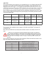
board for the PT-101. A bank of eight white switches can be found near the center of the board.
The convention for the switches is this: down is OFF(or zero), up is ON. With all switches down/
off, the head’s address is set by remote control.
Photo shows address setting switches, RS 485 termination switch,
and RS-232 mode jumpers, located under top panel
NOTE: These are binary address switches. With only switch number 1 in the up position, the head’s
address is 1. With only switch number 2 up, the address is 2. With only switch number 3 up, the
address is 4. With only switch number 4 up, the address is 8. With only switch number 5 up, the
address is 16. With only switch number 6 up, the address is 32. With only switch number 7 up, the
address is 64. The switches may be configured in any manner to arrive at a desired address up to
127 (all switches up=1+2+4+8+16+32+64=127) For example, to set address number 3, switches 1
and 2 should be up. For address 6, switches 2 and 3 should be up (2+4=6).
Note that if the dip switches are set with the unit powered up, the unit power must be cycled off and
back on for the address to be set in memory.
8