1
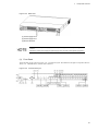
ALAXALA AX3600S and AX2400S
Hardware Instruction Manual
AX36S-H001-50X
Please read the entire manual, and then properly store it.
• Before using the product, be sure to read and understand all the safety precautions.
• Keep the manual somewhere where it can be readily accessed.
Relevant Products
This manual covers the following products: 7 models in the AX2400S series including AX2430S-24T, AX2430S-24T2X, AX2430S-48T,
AX2430S-48T2X, AX2430S-24TD, AX2430S-24T2XD and AX2430S-48TD; and 15 models in the AX3600S series including AX3630S-24T,
AX3630S-24T2X, AX3630S-24P, AX3630S-24TD, AX3630S-24T2XD, AX3630S-24S2XW, AX3630S-48TW, AX3630S-48T2XW,
AX3640S-24T, AX3640S-24TW, AX3640S-24T2XW, AX3640S-24SW, AX3640S-24S2XW, AX3640S-48TW and AX3640S-48T2XW.
Export Restrictions
If you export this product, please check all restrictions, such as Japan's Foreign Exchange and Foreign Trade Law and USA export control laws
and regulations, and carry out all required procedures.
If you require more information, please contact your ALAXALA sales representative.
Trademarks
- Ethernet is a product name of Xerox Corporation.
- Windows is a registered trademark of Microsoft Corporation.
- Other company and product names are trademarks or registered trademarks of their respective owners.
Reading and Storing this Manual
Before you use the equipment, read the manual carefully and make sure that you understand all safety precautions.
After reading the manual, keep it in a convenient place for easy reference.
Notes
Information in this document is subject to change without notice.
Radio Interference
This device is a Class A product based on the standard of the Voluntary Control Council for Interference (VCCI) for information technology
equipment. In a domestic environment this product may cause radio interference in which case the user may be required to take corrective
actions.
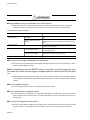
Limits for Harmonic Current Emissions
Conforming products to the standard harmonic current emissions JIS C 61000-3-2.
Conforming devices:
AX-2430-24T
(AX2430S-24T)
AX-2430-24T2X
(AX2430S-24T2X)
AX-2430-48T
(AX2430S-48T)
AX-2430-48T2X
(AX2430S-48T2X)
AX-3630-24T
(AX3630S-24T)
AX-3630-24T2X
(AX3630S-24T2X)
AX-3630-24P
(AX3630S-24P)
AX-3630-24S2XW
(AX3630S-24S2XW)
AX-3630-48TW
(AX3630S-48TW)
AX-3630-48T2XW (AX3630S-48T2XW)
AX-3640-24T
(AX3640S-24T)
AX-3640-24TW
(AX3640S-24TW)
AX-3640-24T2XW (AX3640S-24T2XW)
AX-3640-24SW
(AX3640S-24SW)
AX-3640-24S2XW
(AX3640S-24S2XW)
AX-3640-48TW
(AX3640S-48TW)
AX-3640-48T2XW (AX3640S-48T2XW)
AX-F2430-EPUA
(EPU-A)
AX-F2430-EPUB
(EPU-B)
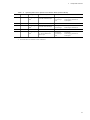
Edition history
December 2005, 1st edition AX36S-H001 (out of print)
December 2005, 2nd edition AX36S-H001-10 (out of print)
July 2006, 3rd edition AX36S-H001-20 (out of print)
January 2007, 4th edition AX36S-H001-30 (out of print)
April 2007, 5th edition AX36S-H001-40 (out of print)
November 2007, 6th edition AX36S-H001-50
Copyright
Copyright (C) 2005, 2007, ALAXALA Networks Corporation. All rights reserved.
Preface
About This Manual
This manual describes the hardware instructions for ALAXALA AX2400S series compact gigabit layer 2 switches and
ALAXALA AX3600S series compact gigabit layer 3 switches. Before you operate the equipment, read this manual carefully
and make sure that you understand all instructions and notes. After reading the manual, keep it in a convenient place
for easy reference.
Intended Readers
This manual is intended for engineers who install and handle the AX2400S and AX3600S series products. It is therefore assumed
that they are familiar with electrical circuits, wiring and networks.
Structure of Manual
Safety Information
Notes for safe use of AX2400S series and AX3600S series switches are described. Make sure to read them prior to using
the switch.
Chapter 1 Components Overview
An overview of the components of the switch is provided.
Chapter 2 Preparation for Installation
Environmental conditions and required preparation for installation of the switch are described.
Chapter 3 Preparation of Interface Cables and Terminals
The interface cables and the terminals used for the devices are described.
Chapter 4 Installation of the Components
The procedures to install the components are provided.
Chapter 5 Expansion, Replacement and Removal
The procedures to expand, replace and remove the switches, external power units (EPUs) and power supply modules are provided.
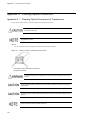
Appendix A Cleaning Optical Connecters
The procedures to clean the optical connectors of the transceivers and the optical fiber cable connecters are described.
Appendix B Physical Specifications of Network Interfaces
The specifications of the interfaces on the device are listed.
Appendix C Specifications of the Setup Terminal
The setup terminal and the connection cable to use for the device are described.
I
Preface
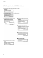
Find Description from the AX2400S Series Manuals
II
Preface
Find Description from the AX3600S Series Manuals
III
Preface
How to Obtain This Manual
For the manuals of AX2400S Series AX3600S series switches, see the following website:
http://www.alaxala.com/
Acronyms
EIA
EPU
FG
G
IEEE
JIS
LAN
LED
MDI
MDI-X
PoE
PS
RS-232C
SD
SFP
TCP/IP
T/R
URL
UTP
XFP
IV
Electronic Industries Alliance
External Power Unit
Frame Ground
Ground
Institute of Electrical and Electronics Engineers, Inc.
Japanese Industrial Standards
Local Area Network
Light Emitting Diode
Medium Dependent Interface
Medium Dependent Interface Crossover
Power over Ethernet
Power Supply
Recommended Standard 232C
Secure Digital
Small Form factor Pluggable
Transmission Control Protocol/Internet Protocol
Transmitter/Receiver
Uniform Resource Locator
Unshielded Twisted Pair
10 gigabit small Form factor Pluggable
Contents
Preface
I
Safety Information
1
Safety - 1
Components Overview
1
1.1 Main Device
2
1.1.1 AX2430S-24T/AX2430S-24TD/AX3630S-24T/AX3630S-24TD/AX3640S-24T Models
3
1.1.2 AX3640S-24TW Model
6
1.1.3 AX2430S-24T2X, AX2430S-24T2XD, AX3630S-24T2X, AX3630S-24T2XD Models
10
1.1.4 AX3640S-24T2XW Model
13
1.1.5 AX3630S-24P Model
18
1.1.6 AX2430S-48T/AX2430S-48TD Models
21
1.1.7 AX3630S-48TW/AX3640S-48TW Models
24
1.1.8 AX2430S-48T2X Model
27
1.1.9 AX3630S-48T2XW/AX3640S-48T2XW Models
30
1.1.10 AX3640S-24SW Model
33
1.1.11 AX3630S-24S2XW/AX3640S-24S2XW Models
36
1.1.12 Accessories
39
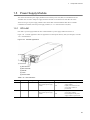
1.2 Power Supply (PS)
44
1.2.1 PS-A01
44
1.2.2 PS-D01
45
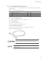
1.2.3 Power Supply Accessories
46
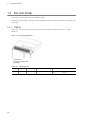
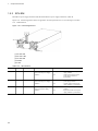
1.3 Fan Unit (FAN)
48
1.3.1 FAN-01
48
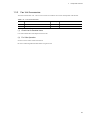
1.3.2 Fan Unit Accessories
49
1.4 External Power Unit (EPU)
50
1.4.1 EPU-A
50
1.4.2 EPU-B
53
1.4.3 EPU Accessories
56
1.5 Power Supply Module
59
1.5.1 EPU-AM
59
1.5.2 EPU-BM
60
1.5.3 Power Supply Module Accessories
61
1.6 Memory Card
62
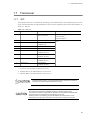
1.7 Transceiver
63
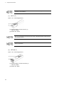
1.7.1 SFP
63
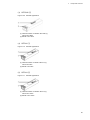
1.7.2 XFP
68
1.7.3 Transceiver Accessories
70
i
Table of Contents
2
Preparation for Installation
71
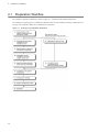
2.1 Preparation Workflow
72
2.2 Installation Conditions
73
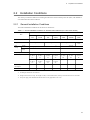
2.2.1 General Installation Conditions
73
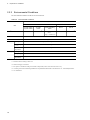
2.2.2 Environmental Conditions
78
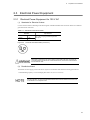
2.3 Electrical Power Equipment
3
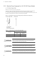
2.3.1 Electrical Power Equipment for 100 VAC
79
2.3.2 Electrical Power Equipment for 200 VAC
80
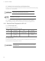
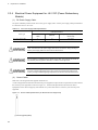
2.3.3 Electrical Power Equipment for -48 VDC (DC Power Models)
82
2.3.4 Electrical Power Equipment for -48 VDC (Power Redundancy Models)
84
2.4 Notes on Electrical Noise
86
2.5 Leakage Current
87
2.6 Environmental Conditions
88
2.7 Where to Install
90
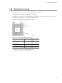
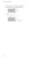
2.8 Maintenance Area
91
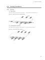
2.9 Cooling Conditions
93
2.9.1 Air Flow
93
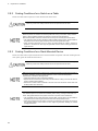
2.9.2 Cooling Conditions for a Switch on a Table
94
2.9.3 Cooling Conditions for a Rack-Mounted Device
94
2.10 Noise of the Switch
95
Preparation of Interface Cables and Terminals
97
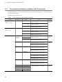
3.1 Connecting Interface Cables and Terminals
98
3.2 Network Interface Specifications
4
100
3.2.1 Ethernet 10/100/1000BASE-T
100
3.2.2 Ethernet 1000BASE-X
101
3.2.3 Ethernet 10GBASE-R
101
Installation of the Components
103
4.1 Necessary Tools
104
4.2 Precautions Before Starting the Installation
105
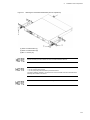
4.3 Installation of the Main Device
106
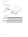
4.3.1 Table Top
106
4.3.2 Rack Mount
107
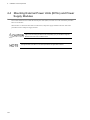
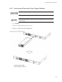
4.4 Mounting External Power Units (EPUs) and Power Supply Modules
ii
79
110
4.4.1 Table Mount
111
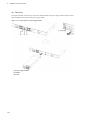
4.4.2 Rack Mount
112
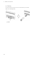
4.4.3 Inserting and Removing Power Supply Modules
115
Table of Contents
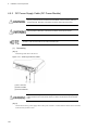
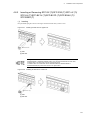
4.5 Connecting and Disconnecting a Power Supply Cable to and from the Main Device
117
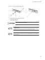
4.5.1 AC Power Supply Cable (AC Power and AC (PoE) Models)
117
4.5.2 AC Power Supply Cable (Power Redundancy Models)
120
4.5.3 DC Power Supply Cable (DC Power Models)
122
4.5.4 DC Power Supply Cable (Power Redundancy Models)
125
4.6 Attaching and Detaching a Power Supply Cable to and from a External Power Unit (EPU)
129
4.6.1 AC Power Supply Cable
129
4.6.2 Stand-by Power Supply Cable
132
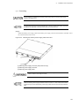
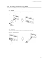
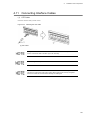
4.7 Inserting and Removing Memory Cards and the Dummy Memory Card
135
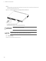
4.7.1 Inserting and Removing Memory Cards
135
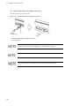
4.7.2 Inserting and Removing the Dummy Memory Card
137
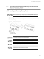
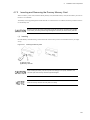
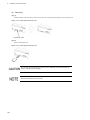
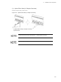
4.8 Inserting and Removing SFPs
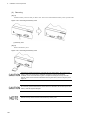
4.8.1 Inserting and Removing SFP-T(T)
139
139
4.8.2 Inserting or Removing SFP-SX (T)/SFP-SX2 (T)/SFP-LX (T)/SFP-LH (T)/SFP-BX1U (T)/SFP-BX1D (T)/
SFP-BX4U (T)/SFP-BX4D (T)
141
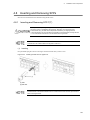
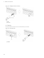
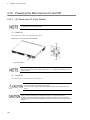
4.9 Inserting and Removing XFPs
143
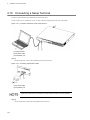
4.10 Connecting a Setup Terminal
144
4.11 Connecting Interface Cables
145
4.12 Powering the Main Device On and Off
148
4.12.1 AC Power and AC (PoE) Models
148
4.12.2 DC Power Model
149
4.12.3 Power Redundancy Model
150
4.13 Powering the External Power Unit (EPU) On or Off
5
152
4.13.1 EPU-A
152
4.13.2 EPU-B
153
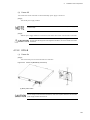
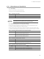
4.14 Miscellaneous Operations
155
Expansion, Replacement and Removal
157
5.1 Necessary Tools
158
5.2 Precautions Before Starting an Installation
159
5.3 Expansion, Replacement and Removal of Main Devices
160
5.4 Expansion, Replacement and Removal of Power Supplies
164
5.5 Replacement of a Fan Unit
168
5.6 Expansion, Replacement and Removal of External Power Units (EPUs)
170
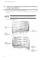
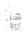
5.7 Expansion, Replacement and Removal of Power Supply Modules
173
iii
Table of Contents
Appendix
Appendix A Cleaning Optical Connectors
176
Appendix A.1 Cleaning Optical Connectors of Transceivers
176
Appendix A.2 Cleaning Optical Fiber Cables
179
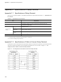
Appendix B Physical Specifications of Network Interfaces
181
Appendix B.1 Ethernet 10BASE-T/100BASE-TX/1000BASE-T
181
Appendix B.2 Ethernet 1000BASE-X Interface
182
Appendix B.3 Ethernet 10GBASE-R Interface
184
Appendix C Specifications of Setup Terminal
iv
175
186
Appendix C.1 Specifications of Setup Terminal
186
Appendix C.2 Specifications of Cable to Connect Setup Terminal
186
Safety Information
To Use AX2400S Series and AX3600S Series Switches Safely
z This manual includes notes for safe use of AX2400S series and AX3600S series switches. Be sure to read
through this document before use.
z After reading this manual, keep it in an accessible place for easy reference.
z To use the switch, follow the instructions and procedures described in this manual.
z Make sure to observe the notes indicated on the switch and in the manual. Otherwise, personal injury or
damage to the switch could occur.
Prior to Use
z Symbols
These symbols in the manual and on the switch are intended to assist you in operating the device safely and properly,
and also to prevent harm to you and other people and damage to your property. Be sure to understand the meanings
of these labels before reading the main contents.
Ignoring instructions marked with this label and using the switch incorrectly could result in
death or serious injury to yourself and others.
Ignoring instructions marked with this label and using the switch incorrectly could result in
serious injury to yourself and others.
Ignoring instructions marked with this label and using the switch incorrectly could result in
serious damage to the switch or nearby property.
Information preceded by this indication is supplementary information that, even if ignored,
will not result in physical injury or serious damage to the switch.
Operation and Action
z Do not perform any operations or actions except those described in this document.
In case of trouble with the device, turn it off, disconnect the power supply cable and then contact the maintenance
staff.
Self-Driven Action
We have striven to provide every note necessary on both the switch and in the manual.
However, a situation beyond our expectations might arise. While operating the switch, it is important for you to pay close
attention in addition to observing the instructions.
Safety - 1
Safety Information
If any problem occurs, immediately turn off the device.
z In the case of smoke, a bad smell or an intrusion of substances or water into the device, follow the
instructions below to turn off the device. Continuous use might cause a fire or an electric shock.
Countermeasures Against Problems
Faulty device
AC power model
AC (PoE) model
Without the external power
unit (EPU)
Turn off the main device and disconnect the power supply
cable.
With the external power unit
(EPU)
Turn off the main device and the power supply module, which
outputs power to the device, and disconnect the power supply
cable.
DC power model
Power redundancy model
Actions
Turn off the main device and open the circuit breaker for the
electrical power equipment.
With AC power supplies
Turn off all power supplies installed the device and disconnect
the power supply cable.
With DC power supplies
Turn off all power supplies installed the device and the circuit
breaker for the electrical power equipment.
EPU
Turn off the EPU and disconnect the power supply cable.
Do not put any foreign substances into the device.
z Do not insert or drop metal objects or flammable materials through the air vents into the device. A fire or
an electric shock might be caused.
When attempting to push the RESET switch, do not use a tool with a fragile tip, a pin
or a paper clip, which can be caught or dropped inside the switch and will not be taken
out.
z When attempting to push the RESET switch, do not use a tool with a fragile tip, a pin or a paper clip, which
can be caught or dropped inside the switch and will not be taken out. A fire or an electric shock might be
caused.
Do not modify the device.
z Do not modify the device. A fire or an electric shock might be caused.
Do not make bump or drop the switch.
z In case that the device is dropped or a component is damaged, turn off the device, disconnect the power
supply cable from the outlet and contact the maintenance staff. Continuous use might cause a fire or an
electric shock.
Do not put any objects on the device.
z Do not put metal objects including pins and paper clips or containers with water such as vases and plant
pots on the device. If such objects get into the device, a fire or an electric shock might be caused.
Safety - 2
Safety Information
Use the device only with the indicated power source.
z Use the device only with the indicated voltage of power. A fire or an electric shock might be caused.
Ensure that the capacity of incoming current to the distribution board should be larger
than the breaker operating current capacity.
z Ensure that the capacity of incoming current to the distribution board should be larger than the breaker
operating current capacity. Otherwise, the breakers cannot operate properly in case of trouble, which might
cause a fire.
Ground the switch.
z For the AC power and the AC (PoE) models, the power redundancy models with AC power supplies, and
the external power unit (EPU), make sure to use an outlet with a ground terminal. Not connecting the
grounded outlet to the switch can cause electric shocks, as well as a cause of failure due to electrical noise.
z For the DC power model and the power redundancy model with DC power supplies, use the ground cable
for grounding. Not connecting the grounded outlet to the switch can cause electric shocks, as well as cause
failures due to electrical noise.
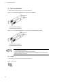
A trained engineer or maintenance staff should attach and detach the DC power
supply cable.
z A trained engineer or maintenance staff should connect and disconnect the DC power supply cable to and
from the electrical power equipment. The terminals of the DC power supply cable are connected to the
electrical power equipment. Wrong handling of the DC power supply cable can cause a fire or an electric
shock.
Prior to connecting or disconnecting the DC power supply cable, turn off the circuit
breaker of the electrical power equipment.
z Prior to connecting or disconnecting the DC power supply cable, turn off the circuit breaker of the electrical
power equipment. Otherwise, a fire or an electric shock might result.
Cover the G and -48 V terminals of the DC power supply cable with an insulation
jacket.
z Cover the G and -48 V terminals of the DC power supply cable (on the electrical power equipment side)
with an insulation jacket. Otherwise, an electric shock might result.
Safety - 3
Safety Information
Cut the DC power supply cable jackets to the specified length.
z To use the DC power supply cable on the power redundancy model, cut the cable jackets (on the switch
side) to 8 to 10 mm.
Too short a sheath length might result in poor contact or a disconnected cable. On the contrary, too long a
sheath length might expose the core wire and cause an electric shock.
Do not use the switch without the protective caps.
z Keep the protective cap in place except when attaching a cable. Otherwise, a fire or an electric shock might
be caused.
Note that EPU-B outputs higher voltage and the label shown below is therefore attached near the stand-by
power supply connector.
Take care of the power supply cable.
z Do not have the power supply cable laid under heavy objects, stretched, bended or processed. The
damaged cable might cause a fire or an electric shock. Pay attention to the rug over the cable, which might
conceal the cable and lead to the cable bearing a heavy load.
z Make sure to use the accessory power supply cable or the specified one. Otherwise, a fire or an electric
shock might result. In addition, use the accessory cable only for this product. Otherwise, a fire or an electric
shock might result.
z If the power supply cable is damaged, exposing the core wires, or is broken, contact the maintenance staff
for a replacement. Continuous use might cause a fire or an electric shock.
z Check for dust on the power supply plug. Securely insert the full length of the blades to exclude any play.
Dust on the plug or insufficient connection might cause a fire or an electric shock.
Do not use a power strip.
z Do not connect multiple appliances of power plugs to one outlet. Doing so can cause a fire as well as circuit
breaker operation due to excessive power consumption affecting other devices.
Prior to inserting or removing the power supply, disconnect the power supply cable.
z Prior to inserting or removing the power supply, disconnect the power supply cable from the power supply.
When the power supply cable is connected, part of the circuit is energized even though the power switch
is off. Therefore, inserting or removing the power supply with the power supply cable connected can cause
a fire or an electric shock.
Safety - 4
Safety Information
Do not install the device on an unstable place.
z Horizontally install the device on a work table that can sufficiently bear the load of the device. Using an
unstable place including wobbly tables and tilted surfaces might cause the switch to fall and possibly cause
injury.
z When mounting the device in a rack, check thoroughly that the device is in a stable condition. Otherwise,
the switch might fall or the rack might tip over, which could result in serious injury.
Do not remove the exterior panels of the device.
z Do not remove the exterior panels of the device. Otherwise, an electric shock might be caused. The label
shown below is attached on the device.
Do not block the air vents of the device.
z Do not block the air vents of the device. Otherwise, the internal heat is not discharged, which might cause
a fire. Keep more than 50 mm of space from the air vents.
Keep your hair or any objects away from the air vents of the device.
z The device has cooling fans. Keep any objects away from the air vents. Otherwise, increasing temperature
inside the device might cause a failure. Also, keep the air vents clear of hair or objects that might be caught
and cause injury.
When moving the device, do not hold the handles of the power supply, the fan unit or
the power supply module.
z When moving the power redundancy model, do not hold the handle of the power supply or the fan unit. The
handle can come off and the device can fall, possibly causing injury. Or the device might be distorted to
cause a fire or an electric shock.
z When moving the EPU, do not hold the handle of the power supply modules. The handle can come off and
the device can fall, which might cause injury. Or the EPU might be distorted to cause a fire or an electric
shock.
Safety - 5
Safety Information
Precautions for transportation
z Prior to moving the device, turn it off and remove all cables from it. Otherwise, distorted or damaged device
cables might cause a fire or an electric shock.
z Since the device might need to be stacked under other things during transportation, put it in the shipping
box. Otherwise, a distorted or damaged device might cause a fire or an electric shock.
Take care of the power supply cable.
z Keep the power supply cable away from heating appliances. Otherwise, the melted cable jacket might
cause a fire or an electric shock.
z Hold the cable plug when connecting or disconnecting the AC power supply cable into or from an outlet.
Pulling the cable part might break the wire.
z Hold the cable connector when connecting or disconnecting the DC power supply cable. Pulling the cable
part might break the wire.
Safety - 6
Safety Information
Prior to turning off the device, shut off all power to the device.
z As for the AC power and AC (PoE) models with backup power supplied from the EPU, turning off the power
switch of the switch does not shut off the power to the switch. Turn off the switches of the switch and the
power supply modules to shut off the power supplies.
z As for the power redundancy model with the redundant power supply, turning off either power switch does
not shut off the power to the switch. Turn off the switches of all power supplies mounted on the switch to
shut off the power supplies.
Pay attention to the laser beam.
z This device uses a laser beam, which is colorless and invisible. Do not directly look into the optical
transmitter/receiver part.
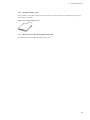
Do not touch the SFP-T(T) during or immediately after operation.
z The temperature of operating an SFP-T(T) can rise up to 65 degrees Celsius after a link is established. Do
not touch it during or immediately after operation. Otherwise, you might get burned.
To remove an SFP-T(T), do either of the procedures below. Otherwise, a burn injury might result.
• When the device is on, block the SFP slot and wait for 5 minutes before removing the SFP.
• Turn off the device and wait for 5 minutes before removing the SFP.
The label shown below is attached to an SFP-T(T).
Do not place the device in a humid or dusty environment.
z Do not place the device in humid or dusty environment. A fire or an electric shock might result.
z When the device is exposed to a large temperature difference (for example, when it is moved from a cold
place to a warm place), dew condensation might occur on the surfaces and inside of the device. If the
device is immediately used as it is, a fire or electric shock might result. After moving the device to a place
with an extreme temperature change, wait a few hours before using it.
Safety - 7
Safety Information
Do not step on or lean against the device. Do not put heavy objects on the device.
z Do not step on or lean against the device. The device might be damaged, or if it becomes unstable, it could
fall, causing injury.
z Do not put anything that is 5 kg or more on the device. The device might be damaged, or if it becomes
unstable, it could fall, causing injury.
Do not touch the inside of the device.
z Do not put your hands inside the device carelessly. The components might cause an injury.
For the power redundancy model, install a fan unit into a slot that does not contain a
power supply.
z For the power redundancy model, install a fan unit into a slot that does not contain a power supply.
Otherwise, a failure might occur due to increasing temperatures inside the device. In addition, the
components might cause injury or invading foreign matter might cause a failure.
For the EPU, use blank panels to cover the slots that do not contain power supply
modules.
z For the EPU, use blank panels to cover the slots that do not contain power supply modules. Otherwise, the
components might cause injury or invading foreign matter might cause a failure.
Cleaning
z Regularly clear dust from the device and its surroundings. Dust does not only possibly interrupt device
operation but also might cause a fire or an electric shock.
Safety - 8
Safety Information
Do not expose the device to high temperatures.
z Placing the device in direct sunlight or near heating appliances such as stoves has a bad influence on the
components.
Keep the device away from TV sets or radios.
z TV sets or radios next to the device might adversely affect each other. When the TV or the radio is noisy,
take the following measures:
• Place the device as far away from the TV set or radio as possible.
• Change the direction of the TV or radio antenna.
• Use a different outlet.
Do not place the device in the environment where hydrogen sulfide is produced or in
a salty atmosphere.
z Any places where hydrogen sulfide is produced such as hot spring resorts or where salt content is rich in
the air, such as seaside areas, might shorten the service life of the device.
Prior to connecting or disconnecting the power supply cable, turn off the switches.
z For the AC power, the AC (PoE) models and the EPU, turn off the device before connecting or
disconnecting the power supply cable.
z As for the power redundancy model, turn off the power supply before connecting or disconnecting the
power supply cable or the cable connector.
z As for the stand-by power supply cable, turn off the power supply module.
When the power supply or the fan unit is replaced with the device turned on, keep the
time limit.
z When the power supply or the fan unit is replaced with the main device turned on, do not leave the device
more than three minutes without the power supply and the fan unit. Otherwise, a failure might occur due
to increasing temperatures inside the device.
Safety - 9
Safety Information
Prior to inserting or removing the power supply module, turn off the switches.
z Prior to inserting or removing the power supply module, turn off the switch of the relevant power supply
module. Otherwise, a fault might occur or the device might fail. The label shown below is attached on the
EPU.
Prior to turning on the main switch of the EPU, turn off the power supply modules.
z Prior to turn on the main switch of the EPU, make sure all power switches of the inserted power supply
modules are turned off.
When backup power is still supplied to the device, do not turn off the main switch of
the EPU.
z When the main switch of the EPU is turned off, all backup power supply to the device is shut off. When
backup power is still supplied to the device, do not turn off the main switch of the EPU.
Carefully handle the memory card and the dummy memory card.
z When inserting the memory card or dummy memory card, do not push it too strongly or too quickly. Do not
forcibly pull a locked card to remove it. Otherwise, the connector part of the memory card slot might be
damaged.
z Make sure to remove the memory card and the dummy memory card before moving the main device.
Excessive stress applied on the card during transfer might damage the connector part of the memory card
slot.
Do not remove the memory card or turn off the device while the ACC LED is lit up.
z The device is accessing the memory card whenever the ACC LED on the device front panel is lit up. Do
not remove the memory card or turn off the device. Otherwise, the memory card might be damaged.
In addition, some commands take long time to access the memory card after being executed. Confirm that
access has ended before removing the memory card or turning the power supply off.
Safety - 10
Safety Information
Do not attach other labels to the transceiver.
z The transceivers have labels to certify that they are standard products of the manufacturer or ALAXALA.
These labels are attached so as not to disturb heat radiation from the transceiver or the mechanism to
avoid dropping from the cage.
Attaching a label on an interfering part with heat radiation or the mechanism to avoid dropping from the
cage might cause a failure in the transceiver or damage to the device.
Do not shut off the power to the device while the ST1 LED is blinking green.
z In the following situations, do not switch off the device until the blinking green ST1 LED on the device front
panel turns to a constant green. Otherwise, the device might break down:
• Updating software
While carrying or packing the device and optional components, wear an antistatic
wrist strap.
z Make sure to wear an antistatic wrist strap. Handling the device without an antistatic wrist strap might
damage the device due to an electrostatic discharge.
Carefully carry or pack optional components.
z Do not touch the connector part of the transceiver, the memory card, the power supply, the fan unit and the
power supply module while carrying or packing them. For storage, put them in an antistatic bag.
Cleaning
z To clean the exterior of the device, use a dry clean cloth or those that have been immersed in water or mild
detergent and wrung out. Do not use volatile organic solvents, such as benzine and paint thinner,
chemicals, chemical dusters or pesticides. Otherwise, discoloration, distortion or failure might result.
Long-term shut down
z When the device is not used for a long time (for example, during a long vacation or trip), remove the power
supply cable from the outlet for safety. When the DC power supply is used, turn off the circuit breaker of
your electrical power equipment.
Disposal of the device
z Dispose of the device according to the ordinances and regulations of your municipality or contact your local
waste disposal facilities.
Safety - 11
Safety Information
Safety - 12
1
Components Overview
This chapter provides an overview of the various parts of the switch.
1.1 Main Device
1.2 Power Supply (PS)
1.3 Fan Unit (FAN)
1.4 External Power Unit (EPU)
1.5 Power Supply Module
1.6 Memory Card
1.7 Transceiver
1
1.
Components Overview
1.1
Main Device
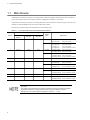
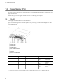
AX2400S series switches provide layer 2 switching that is capable of 10-gigabit communication. These switches are
good as edge switches for local area networks and server aggregation switches in a server farm.
AX3600S series switches provide layer 3 switching and can be used as distribution switches for large-scale LANs, core
switches for small and middle-scale LANs and customer edge switches.
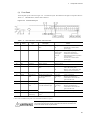
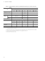
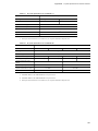
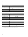
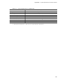
The following models belong to the AX2400S series and AX3600S series.
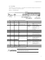
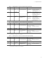
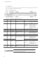
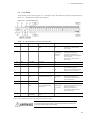
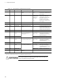
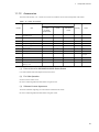
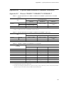
Table 1-1 List of AX2400S series and AX3600S series switches
LAN Interface
Number
1
2
10/100/1000
BASE-T
SFP slot
XFP slot
24 ports
4 slots
-
24 ports
4 slots
2 slots
Series
Name
Model Name
AX2400S
AX2430S-24T
AX2430S-24TD
(AC power model)
(DC power model)
AX3600S
AX3630S-24T
AX3630S-24TD
AX3640S-24T
AX3640S-24TW
(AC power model)
(DC power model)
(AC power model)
(power redundancy model)
AX2400S
AX2430S-24T2X
(AC power model)
AX2430S-24T2XD (DC power model)
AX3600S
AX3630S-24T2X
(AC power model)
AX3630S-24T2XD (DC power model)
AX3640S-24T2XW (power redundancy model)
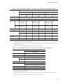
3
24 ports (PoE)
4 slots
-
AX3600S
AX3630S-24P
(AC (PoE) model)
4
48 ports
4 slots
-
AX2400S
AX2430S-48T
AX2430S-48TD
(AC power model)
(DC power model)
AX3600S
AX3630S-48TW
AX3640S-48TW
(power redundancy model)
(power redundancy model)
AX2400S
AX2430S-48T2X
(AC power model)
AX3600S
AX3630S-48T2XW (power redundancy model)
AX3640S-48T2XW (power redundancy model)
5
48 ports
-
2 slots
6
4 ports
24 slots
-
AX3600S
AX3640S-24SW
(power redundancy model)
7
4 ports
24 slots
2 slots
AX3600S
AX3630S-24S2XW (power redundancy model)
AX3640S-24S2XW (power redundancy model)
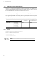
This switch has a flash disk to store the operating system, the configuration data and the log
information.
The number of times the disk can be written to is limited, and should be noted during operation.
For detailed precautions on writing data to the flash memory, see Section 11 Device
Management in the Software Manual Configuration Guide Vol. 1. : 11 TM
2
1.
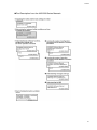
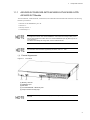
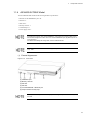
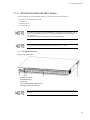
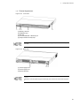
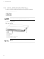
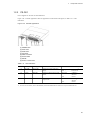
1.1.1
Components Overview
AX2430S-24T/AX2430S-24TD/AX3630S-24T/AX3630S-24TD/
AX3640S-24T Models
The AX2430S-24T, AX2430S-24TD, AX3630S-24T, AX3630S-24TD and AX3640S-24T models have the following
hardware specifications:
• Ethernet 10/100/1000BASE-T ports: 24
• SFP slots: 4
• Memory card slot: 1
• CONSOLE port: 1
Since switch ports 1 to 4 are shared by the SFP slots and 10/100/1000BASE-T, the ports cannot
be assigned to both SFP and 10/100/1000BASE-T at the same time. Configure each port so
that it is either assigned to an SFP slot or as a 10/100/1000BASE-T port. (By default, ports 1 to
4 are SFP slots.)
For details about editing the configuration, see the Software Manual.
For information about the SFPs supported by this switch, see 1.7.1
(1)
SFP.
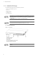
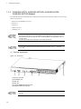
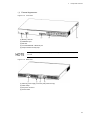
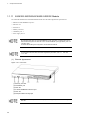
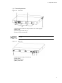
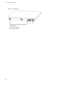
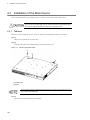
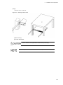
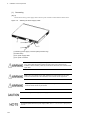
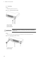
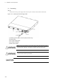
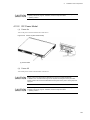
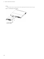
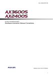
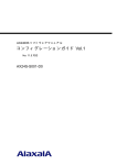
External Appearance
Figure 1-1 Front View
(1) Memory card slot
(2) CONSOLE port
(3) SFP slots
(4) 10/100/1000BASE-T Ethernet ports
(5) Tamper-evident security tape
Do not peel off the tamper-evident security tape. Removing the tape makes the warranty null
and void.
3
1.
Components Overview
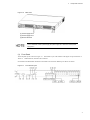
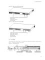
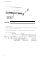
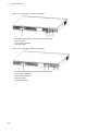
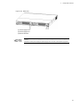
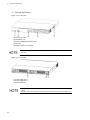
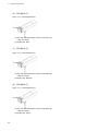
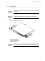
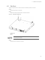
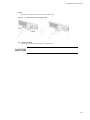
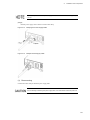
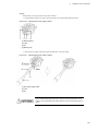
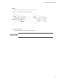
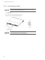
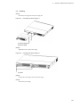
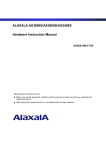
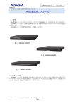
Figure 1-2 Back View of the AC Power Model
(1) Stand-by power supply connector (with protective cap)
(2) Cable clamp
(3) AC power connector
(4) Power switch
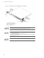
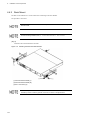
Figure 1-3 Back View of the DC Power Model
(1) Stand-by power supply connector (with protective cap)
(2) DC power connector 2
(3) DC power connector 1
(4) Power switch
(5) Ground terminal
4
1.
Components Overview
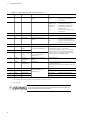
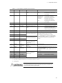
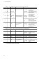
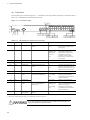
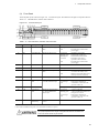
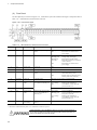
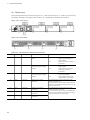
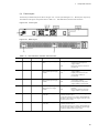
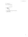
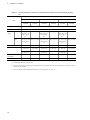
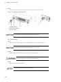
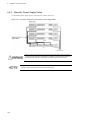
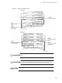
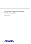
(2) Front Panel
The front panel layout is shown in Figure 1-4 Front Panel Layout. The numbers in the figure correspond to those in
Table 1-2 LED Indications, Switches and Connectors.
Figure 1-4 Front Panel Layout
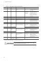
Table 1-2 LED Indications, Switches and Connectors
Number
Name
Type
Description
Details
(1)
PWR
Green LED
Indicates the power supply
status.
Lit in green
Off
: Powered-on
: Powered-off or failure with power
supply
(2)
ST1
Green/Red
LED
Indicates the device status.
Lit in green
Blinking green
Blinking red
Lit in red
: Standing by or running
: Getting ready (starting up)
: Partial failure with the switch
: Fatal failure with the switch
(cannot be used)
: Powered-off or failure with a
power supply
Off
(3)
ST2
Green LED
(Not used)
Off
(4)
MC
Connector
Memory card slot
Memory card slot
(5)
ACC
Green LED
Indicates the memory card
status.
Lit
Off
: Accessing the memory card. (Do
not remove the memory card.)
: Memory card is in idle mode. (The
memory card can be removed.)
(6)
CONSOLE
Connector
CONSOLE port
RS-232C port to connect a console terminal.
(7)
LINK
Green/Orange
LED
Indicates the operating status of
an SFP slot Ethernet port.
Lit in green
Lit in orange
Off
(8)
T/R
Green LED
Lit in green
: Sending or receiving frames
Green/Orange
LED
Indicates the operating status of
a 10/100/1000BASE-T Ethernet
port.
Lit in green
Blinking green
: A link is established.
: A link is established and frames are
being sent or received.
: Detecting line disturbances.
: A link failure or block when the
green ST1 LED is lit.
(9)
1-24
Lit in orange
Off
(10)
RESET
Switch
(momentary)
Manual reset switch for the
switch*1
: A link is established.
: Detecting line disturbances.
: Alink failure or block when the
green ST1 LED is lit
Restarts the device.
*1 The switch is behind the front panel. Use a small-head screwdriver to press it.
When attempting to push the RESET switch, do not use a tool with fragile tip,
pin or paper clip that can be caught or dropped inside and will not be taken out.
A fire or an electric shock may be caused.
5
1.
Components Overview
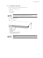
1.1.2
AX3640S-24TW Model
The AX3640S-24TW model has the following hardware specifications:
• Ethernet 10/100/1000BASE-T ports: 24
• SFP slots: 4
• Memory card slot: 1
• CONSOLE port: 1
• Power supply slots: 2
Since switch ports 1 to 4 are shared by the SFP slots and 10/100/1000BASE-T, the ports cannot
be assigned to both SFP and 10/100/1000BASE-T at the same time. Configure each port so
that it is either assigned to an SFP slot or as a 10/100/1000BASE-T port. (By default, ports 1 to
4 are SFP slots.)
For details about editing the configuration, see the Software Manual.
For information about the SFPs supported by the switch, see 1.7.1
SFP.
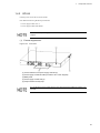
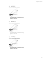
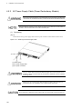
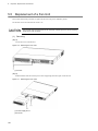
(1) External Appearance
Figure 1-5 Front View
(1) Memory card slot
(2) CONSOLE port
(3) SFP slots
(4) 10/100/1000BASE-T Ethernet ports
(5) Tamper-evident security tape
Do not peel off the tamper-evident security tape. Removing the tape makes the warranty null
and void.
6
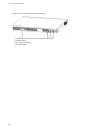
1.
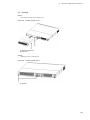
Figure 1-6
Components Overview
Back View
(1) Power supply slot 2
(2) Power supply slot 1
(3) Ground terminal
To build a redundant power supply system, insert power supplies into both power supply slots
1 and 2. Otherwise, insert a power supply into power supply slot 1 and a fan unit into power
supply slot 2.
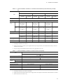
(2) Front Panel
The front panel layout is shown in Figure 1-7 Front Panel Layout. The numbers in the figure correspond to those in
Table 1-3 LED Indications, Switches and Connectors.
Note that the AX3640S-24TW model has a mode button to switch how Ethernet port statuses are shown.
Figure 1-7 Front Panel Layout
7
1.
Components Overview
Table 1-3 LED Indications, Switches and Connectors
Number
Name
Type
Description
Details
(1)
PWR
Green LED
Indicates the power supply
status.
Lit in green
Off
: Powered-on.
: Powered-off or a failure with a
power supply.
(2)
ST1
Green/Red LED
Indicates the device status.
Lit in green
Blinking green
Blinking red
Lit in red
: Standing by or operating.
: Getting ready (starting up).
: Partial failure with the switch
: Fatal failure with the switch
(cannot be used)
: Powered-off or a failure with a
power supply.
Off
(3)
ST2
Green LED
(Not used)
Off
(4)
MC
Connector
Memory card slot
Memory card slot
(5)
ACC
Green LED
Indicates the memory card
status.
Lit
Off
: Accessing the memory card. (Do
not remove the memory card.)
: Memory card is in idle mode. (The
memory card can be removed.)
(6)
CONSOLE
Connector
CONSOLE port
RS-232C port to connect a console terminal.
(7)
LINK
Green/Orange
LED
Indicates the operating status
of an SFP slot Ethernet port.
(8)
T/R
Green LED
(9)
1-24
Green/Orange
LED
Indicates the operating status
of a 10/100/1000BASE-T
Ethernet port.
What these LEDs mean depends on the selected LED
indication mode from (12) to (15) below.
For meanings of LEDs, see Table 1-4 Operating
Status in a Specific LED Indication Mode (LINK
Mode) to Table 1-6 Operating Status in a Specific
LED Indication Mode (DUPLEX Mode).
(10)
RESET
Switch
(momentary)
Manual reset switch of the
Restarts the device.
device*1
(11)
MODE
Button
(momentary)
Mode button
Changing the LED indication modes from (12) to (15)
by pressing this button.
(The order is as follows: LINK > SPEED > FDX > EX
> LINK...)
(12)
LINK
Green LED
Lit in green
: LINK mode is selected.
(13)
SPEED
Green LED
Corresponding LED indication
mode is selected for the
Ethernet ports.
Lit in green
: SPEED mode is selected.
(14)
FDX
Green LED
Lit in green
: DUPLEX mode is selected.
(15)
EX*2
Green LED
Lit in green
: Extension mode is selected.
*1 The switch is behind the front panel. Use a small-head screwdriver to press it.
*2 Not supported.
When attempting to push the RESET switch, do not use a tool with fragile tip,
pin or paper clip that can be caught or dropped inside and will not be taken out.
A fire or an electric shock may be caused.
8
1.
Components Overview
Table 1-4 Operating Status in a Specific LED Indication Mode (LINK Mode)
Number
Name
Type
(7)
LINK
Green/Orange
LED
(8)
T/R
Green LED
Description
Indicates the operating status
of an SFP slot Ethernet port.
Details
Lit in green
Lit in orange
Off
: A link is established.
: Detecting line disturbances.
: A link failure or block when the
green ST1 LED is lit.
Blinking green
: A link is established and frames are
being sent or received.
: The switch is in any other status
except sending or receiving when
the green ST1 LED is lit.
Off
(9)
1-24
Green/Orange
LED
Indicates the operating status
of a 10/100/1000BASE-T
Ethernet port.
Lit in green
Blinking green
Lit in orange
Off
: A link is established.
: A link is established and frames are
being sent or received.
: Detecting line disturbances.
: A link failure or block when the
green ST1 LED is lit.
Table 1-5 Operating Status in a Specific LED Indication Mode (SPEED Mode)
Number
(7)
Name
LINK
Type
Green/Orange
LED
Description
Indicates the operating status
of an SFP slot Ethernet port.
Details
Lit in green:100 Mbps*1
Blinking green:1000 Mbps*1
Lit in orange
: Detecting line disturbances.
Off:10 Mbps*1
(8)
T/R
Green LED
(Not used)
Off
(9)
1-24
Green/Orange
LED
Indicates the operating status
of a 10/100/1000BASE-T
Ethernet port.
Lit in green:100 Mbps*1
Blinking green:1000 Mbps*1
Lit in orange
: Detecting line disturbances.
Off:10 Mbps*1
*1 These indications are valid after a link is established.
Table 1-6 Operating Status in a Specific LED Indication Mode (DUPLEX Mode)
Number
(7)
Name
LINK
Type
Green/Orange
LED
Description
Indicates the operating status
of an SFP slot Ethernet port.
Details
Lit in green:Full duplex*1
Lit in orange
: Detecting line disturbances.
Off:Half duplex*1
(8)
T/R
Green LED
(Not used)
Off
(9)
1-24
Green/Orange
LED
Indicates the operating status
of a 10/100/1000BASE-T
Ethernet port.
Lit in green:Full duplex*1
Lit in orange
: Detecting line disturbances.
Off:Half duplex*1
*1 These indications are valid after a A link is established.
9
1.
Components Overview
1.1.3
AX2430S-24T2X, AX2430S-24T2XD, AX3630S-24T2X,
AX3630S-24T2XD Models
The AX2430S-24T2X, AX2430S-24T2XD, AX3630S-24T2X and AX3630S-24T2XD models have the following
hardware specifications:
• Ethernet 10/100/1000BASE-T ports: 24
• SFP slots: 4
• XFP slots: 2
• Memory card slot: 1
• CONSOLE port: 1
Since switch ports 1 to 4 are shared by the SFP slots and 10/100/1000BASE-T, the ports cannot
be assigned to both SFP and 10/100/1000BASE-T at the same time. Configure each port so
that it is either assigned to an SFP slot or as a 10/100/1000BASE-T port. (By default, ports 1 to
4 are SFP slots.)
For details about editing the configuration, see the Software Manual.
For information about the SFPs and XFPs supported by the switch, see 1.7.1 SFP and
1.7.2 XFP.
(1) External Appearance
Figure 1-8 Front View
(1) Memory card slot
(2) CONSOLE port
(3) XFP slot
(4) SFP slot
(5) 10/100/1000BASE-T Ethernet port
(6) Tamper-evident security tape
Do not peel off the tamper-evident security tape. Removing the tape makes the warranty null
and void.
10
1.
Components Overview
Figure 1-9 Back View of the AC Power Model
(1) Stand-by power supply connector (with protective cap)
(2) Cable clamp
(3) AC power connector
(4) Power switch
Figure 1-10 Back View of the DC Power Model
(1) Stand-by power supply connector (with protective cap)
(2) DC power connector 2
(3) DC power connector 1
(4) Power switch
(5) Ground terminal
(2) Front Panel
The front panel layout is shown in Figure 1-11 Front Panel Layout. The numbers in the figure correspond to those in
Table 1-7 LED Indications, Switches and Connectors.
Figure 1-11 Front Panel Layout
11
1.
Components Overview
Table 1-7 LED Indications, Switches and Connectors
Number
Name
Type
Description
Details
(1)
PWR
Green LED
Indicates the power supply
status.
Lit in green
Off
: Powered-on.
: Powered-off or a failure with a
power supply.
(2)
ST1
Green/Red LED
Indicates the device status.
Lit in green
Blinking green
Blinking red
Lit in red
: Standing by or operating.
: Getting ready (starting up).
: Partial failure with the switch
: Fatal failure in the device
(operation cannot continue)
: Powered-off or a failure with a
power supply.
Off
(3)
ST2
Green LED
(Not used)
Off
(4)
MC
Connector
Memory card slot
Memory card slot
(5)
ACC
Green LED
Indicates the memory card
status.
Lit
Off
: Accessing the memory card. (Do
not remove the memory card.)
: Memory card is in idle mode. (The
memory card can be removed.)
(6)
CONSOLE
Connector
CONSOLE port
RS-232C port to connect a console terminal.
(7)
LINK
Green/Orange
LED
Indicates the operating status
of an SFP slot Ethernet port.
Lit in green
Lit in orange
Off
: A link is established.
: Detecting line disturbances.
: A link failure or block when the
green ST1 LED is lit.
(8)
T/R
Green LED
Lit in green
: Sending or receiving frames.
(9)
LINK
Green/Orange
LED
Lit in green
Lit in orange
Off
: A link is established.
: Detecting line disturbances.
: A link failure or block when the
green ST1 LED is lit.
(10)
T/R
Green LED
Blinking green
: Sending or receiving frames.
(11)
1-24
Green/Orange
LED
Lit in green
Blinking green
: A link is established.
: A link is established and frames are
being sent or received.
: Detecting line disturbances.
: A link failure or block when the
green ST1 LED is lit.
Indicates the operating status
of an XFP slot Ethernet port.
Indicates the operating status
of a 10/100/1000BASE-T
Ethernet port.
Lit in orange
Off
(12)
RESET
Switch
(momentary)
Manual reset switch of the
Restarts the device.
device*1
*1 The switch is behind the front panel. Use a small-head screwdriver to press it.
When attempting to push the RESET switch, do not use a tool with fragile tip,
pin or paper clip that can be caught or dropped inside and will not be taken out.
A fire or an electric shock may be caused.
12
1.
1.1.4
Components Overview
AX3640S-24T2XW Model
The AX3640S-24T2XW model has the following hardware specifications:
• Ethernet 10/100/1000BASE-T ports: 24
• SFP slots: 4
• XFP slots: 2
• Memory card slot: 1
• CONSOLE port: 1
• Power supply slots: 2
Since switch ports 1 to 4 are shared by the SFP slots and 10/100/1000BASE-T, the ports cannot
be assigned to both SFP and 10/100/1000BASE-T at the same time. Configure each port so
that it is either assigned to an SFP slot or as a 10/100/1000BASE-T port. (By default, ports 1 to
4 are SFP slots.)
For details about editing the configuration, see the Software Manual.
For information about the SFPs and XFPs supported by the switch, see 1.7.1
1.7.2 XFP.
(1)
SFP and
External Appearance
Figure 1-12 Front View
(1) CONSOLE port
(2) Memory card slot
(3) XFP slot
(4) SFP slot
(5) 10/100/1000BASE-T Ethernet port
(6) Tamper-evident security tape
Do not peel off the tamper-evident security tape. Removing the tape makes the warranty null
and void.
13
1.
Components Overview
Figure 1-13 External Appearance
(1) Power supply slot 2
(2) Power supply slot 1
(3) Ground terminal
To build a redundant power supply system, mount power supplies into both power supply slots
1 and 2. Otherwise, mount a power supply into power supply slot 1 and a fan unit into power
supply slot 2.
(2)
Front Panel
The front panel layout is shown in Figure 1-14 Front Panel Layout. The numbers in the figure correspond to those in
Table 1-8 LED Indications, Switches and Connectors.
Note that the AX3640S-24T2XW model has a mode button to switch how the Ethernet port status is shown.
Figure 1-14 Front Panel Layout
14
1.
Components Overview
Table 1-8 LED Indications, Switches and Connectors
Number
Name
Type
Description
Details
(1)
PWR
Green LED
Indicates the power supply
status.
Lit in green
Off
: Powered-on.
: Powered-off or a failure with a
power supply.
(2)
ST1
Green/Red LED
Indicates the device status.
Lit in green
Blinking green
Blinking red
Lit in red
: Standing by or operating.
: Getting ready (starting up).
: Partial failure with the switch
: Fatal failure in the device
(operation cannot continue)
: Powered-off or a failure with a
power supply.
Off
(3)
ST2
Green LED
(Not used)
Off
(4)
MC
Connector
Memory card slot
Memory card slot
(5)
ACC
Green LED
Indicates the memory card
status.
Lit
Off
: Accessing the memory card. (Do
not remove the memory card.)
: Memory card is in idle mode. (The
memory card can be removed.)
(6)
CONSOLE
Connector
CONSOLE port
RS-232C port to connect a console terminal.
(7)
LINK
Green/Orange
LED
Indicates the operating status
of an SFP slot Ethernet port.
(8)
T/R
Green LED
(9)
LINK
Green/Orange
LED
(10)
T/R
Green LED
What these LEDs mean depends on the selected LED
indication mode from (14) to (17) below.
For meanings of LED indications, see Table
1-9 Operating Status in a Specific LED Indication
Mode (LINK Mode) to Table 1-11 Operating Status
in the Specific LED Indication Mode (DUPLEX
Mode).
(11)
1-24
Green/Orange
LED
Indicates the operating status
of a 10/100/1000BASE-T
Ethernet port.
(12)
RESET
Switch
(momentary)
Manual reset switch of the
Indicates the operating status
of an XFP slot Ethernet port.
Restarts the device.
device*1
(13)
MODE
Button
(momentary)
Mode button
Changing the LED indication modes from (14) to (17)
by pressing this button.
(The order is as follows: LINK > SPEED > FDX > EX
> LINK...)
(14)
LINK
Green LED
Lit in green
: LINK mode is selected.
(15)
SPEED
Green LED
Corresponding LED indication
mode is selected for the
Ethernet ports.
Lit in green
: SPEED mode is selected.
(16)
FDX
Green LED
Lit in green
: DUPLEX mode is selected.
(17)
EX*2
Green LED
Lit in green
: Extension mode is selected.
*1 The switch is behind the front panel. Use a small-head screwdriver to press it.
*2 Not supported.
When attempting to push the RESET switch, do not use a tool with fragile tip,
pin or paper clip that can be caught or dropped inside and will not be taken out.
A fire or an electric shock may be caused.
15
1.
Components Overview
Table 1-9 Operating Status in a Specific LED Indication Mode (LINK Mode)
Number
Name
Type
(7)
LINK
Green/Orange
LED
(8)
T/R
Green LED
Description
Indicates the operating status
of an SFP slot Ethernet port.
Details
Lit in green
Lit in orange
Off
: A link is established.
: Detecting line disturbances.
: A link failure or block when the
green ST1 LED is lit.
Blinking green
: A link is established and frames are
being sent or received.
: The device is in any other status
except sending or receiving when
the green ST1 LED is lit.
Off
(9)
LINK
Green/Orange
LED
(10)
T/R
Green LED
Indicates the operating status
of an XFP slot Ethernet port.
Lit in green
Lit in orange
Off
: A link is established.
: Detecting line disturbances.
: A link failure or block when the
green ST1 LED is lit.
Blinking green
: A link is established and frames are
being sent or received.
: The device is in any other status
except sending or receiving when
the green ST1 LED is lit.
Off
(11)
1-24
Green/Orange
LED
Indicates the operating status
of a 10/100/1000BASE-T
Ethernet port.
Lit in green
Blinking green
Lit in orange
Off
: A link is established.
: A link is established and frames are
being sent or received.
: Detecting line disturbances.
: A link failure or block when the
green ST1 LED is lit.
Table 1-10 Operating Status in a Specific LED Indication Mode (SPEED Mode)
Number
(7)
Name
LINK
Type
Green/Orange
LED*1
Description
Indicates the operating status
of an SFP slot Ethernet port.
Lit in green
: 100 Mbps*1
Blinking green
Lit in orange
: 1000 Mbps*1
: Detecting line disturbances.
Off
: 10 Mbps*1
(8)
T/R
Green LED
(Not used)
Off
(9)
LINK
Green/Orange
LED
Indicates the operating status
of an XFP slot Ethernet port.
Blinking green
Lit in orange
(10)
T/R
Green LED
(Not used)
Off
(11)
1-24
Green/Orange
LED
Indicates the operating status
of a 10/100/1000BASE-T
Ethernet port.
Lit in green
: 100 Mbps*1
Blinking green
Lit in orange
: 1000 Mbps*1
: Detecting line disturbances.
Off
: 10 Mbps*1
*1 These indications are valid after a link is established.
16
Details
: 10 Gbps*1
: Detecting line disturbances.
1.
Components Overview
Table 1-11 Operating Status in the Specific LED Indication Mode (DUPLEX Mode)
Number
(7)
Name
LINK
Type
Green/Orange
LED
(8)
T/R
(9)
LINK
*1
Description
Indicates the operating status
of an SFP slot Ethernet port.
Details
Lit in green
Lit in orange
: Full duplex*1
: Detecting line disturbances.
Off
: Half duplex*1
Green LED
(Not used)
Off
Green/Orange
LED*1
Indicates the operating status
of an XFP slot Ethernet port.
Lit in green
Lit in orange
: Full duplex*1
: Detecting line disturbances.
(10)
T/R
Green LED
(Not used)
Off
(11)
1-24
Green/Orange
Indicates the operating status
of a 10/100/1000BASE-T
Ethernet port.
Lit in green
Lit in orange
: Full duplex*1
: Detecting line disturbances.
Off
: Half duplex*1
LED*1
*1 These indications are valid after a link is established.
17
1.
Components Overview
1.1.5
AX3630S-24P Model
The AX3630S-24P model has the following hardware specifications:
• Ethernet 10/100/1000BASE-T ports (PoE supported): 24
• SFP slots: 4
• Memory card slot: 1
• CONSOLE port: 1
Since switch ports 1 to 4 are shared by the SFP slots and 10/100/1000BASE-T, the ports cannot
be assigned to both SFP and 10/100/1000BASE-T at the same time. Configure each port so
that it is either assigned to an SFP slot or as a 10/100/1000BASE-T port. (By default, ports 1 to
4 are SFP slots.)
For details about editing the configuration, see the Software Manual.
The Type A PoE system (Alternative A) is used for the switch. For details, see 3.2.1
10/100/1000BASE-T.
For information about the SFPs supported by the switch, see 1.7.1
18
SFP.
Ethernet
1.
(1)
Components Overview
External Appearance
Figure 1-15 Front View
(1) Memory card slot
(2) CONSOLE port
(3) SFP slot
(4) 10/100/1000BASE-T Ethernet port
(5) Tamper-evident security tape
Do not peel off the tamper-evident security tape. Removing the tape makes the warranty null
and void.
Figure 1-16 Back View
(1) Stand-by power supply connector (with protective cap)
(2) Cable clamp
(3) AC power connector
(4) Power switch
19
1.
Components Overview
(2)
Front Panel
The front panel layout is shown in Figure 1-17 Front Panel Layout. The numbers in the figure correspond to those in
Table 1-12 LED Indications, Switches and Connectors.
Figure 1-17 Front Panel Layout
Table 1-12 LED Indications, Switches and Connectors
Number
Name
Type
Description
Details
(1)
PWR
Green LED
Indicates the power supply
status.
Lit in green
Off
: Powered-on.
: Powered-off or a failure with a
power supply.
(2)
ST1
Green/Red LED
Indicates the device status.
Lit in green
Blinking green
Blinking red
Lit in red
: Standing by or operating.
: Getting ready (starting up).
: Partial failure with the switch
: Fatal failure in the device
(operation cannot continue)
: Powered-off or a failure with a
power supply.
Off
(3)
ST2
Green LED
(Not used)
Off
(4)
MC
Connector
Memory card slot
Memory card slot
(5)
ACC
Green LED
Indicates the memory card
status.
Lit
Off
: Accessing the memory card. (Do
not remove the memory card.)
: Memory card is in idle mode. (The
memory card can be removed.)
(6)
CONSOLE
Connector
CONSOLE port
RS-232C port to connect a console terminal.
(7)
LINK
Green/Orange
LED
Indicates the operating status
of an SFP slot Ethernet port.
Lit in green
Lit in orange
Off
: A link is established.
: Detecting line disturbances.
: A link failure or block when the
green ST1 LED is lit.
(8)
T/R
Green LED
Lit in green
: Sending or receiving frames.
(9)
1-24
Green/Orange
LED
Lit in green
Blinking green
: A link is established.
: A link is established and frames are
being sent or received.
: Detecting line disturbances.
: A link failure or block when the
green ST1 LED is lit.
Indicates the operating status
of a 10/100/1000BASE-T
Ethernet port.
Lit in orange
Off
(10)
RESET
Switch
(momentary)
Manual reset switch of the
device*1
Restarts the device.
*1 The switch is behind the front panel. Use a small-head screwdriver to press it.
When attempting to push the RESET switch, do not use a tool with fragile tip,
pin or paper clip that can be caught or dropped inside and will not be taken out.
A fire or an electric shock may be caused.
20
1.
1.1.6
Components Overview
AX2430S-48T/AX2430S-48TD Models
The AX2430S-48T and AX2430S-48TD models have the following hardware specifications:
• Ethernet 10/100/1000BASE-T ports: 48
• SFP slots: 4
• Memory card slot: 1
• CONSOLE port: 1
Since switch ports 1 to 4 are shared by the SFP slots and 10/100/1000BASE-T, the ports cannot
be assigned to both SFP and 10/100/1000BASE-T at the same time. Configure each port so
that it is either assigned to an SFP slot or as a 10/100/1000BASE-T port. (By default, ports 1 to
4 are SFP slots.)
For details about editing the configuration, see the Software Manual.
For information about the SFPs supported by the switch, see 1.7.1
(1)
SFP.
External Appearance
Figure 1-18 Front View
(1) Memory card slot
(2) CONSOLE port
(3) SFP slot
(4) 10/100/1000BASE-T Ethernet port
(5) Tamper-evident security tape
Do not peel off the tamper-evident security tape. Removing the tape makes the warranty null
and void.
21
1.
Components Overview
Figure 1-19 Back View of the AC Power Model
(1) Stand-by power supply connector (with protective cap)
(2) Cable clamp
(3) AC power connector
(4) Power switch
Figure 1-20 Back View of the DC Power Model
(1) Stand-by power supply connector (with protective cap)
(2) DC power connector 2
(3) DC power connector 1
(4) Power switch
(5) Ground terminal
22
1.
Components Overview
(2) Front Panel
The front panel layout is shown in Figure 1-21 Front Panel Layout. The numbers in the figure correspond to those in
Table 1-13 LED Indications, Switches and Connectors.
Figure 1-21 Front Panel Layout
Table 1-13 LED Indications, Switches and Connectors
Number
Name
Type
Description
Details
(1)
PWR
Green LED
Indicates the power supply
status.
Lit in green
Off
: Powered-on.
: Powered-off or a failure with a
power supply.
(2)
ST1
Green/Red LED
Indicates the device status.
Lit in green
Blinking green
Blinking red
Lit in red
: Standing by or operating.
: Getting ready (starting up).
: Partial failure with the switch
: Fatal failure in the device
(operation cannot continue)
: Powered-off or a failure with a
power supply.
Off
(3)
ST2
Green LED
(Not used)
Off
(4)
MC
Connector
Memory card slot
Memory card slot
(5)
ACC
Green LED
Indicates the memory card
status.
Lit
Off
: Accessing the memory card. (Do
not remove the memory card.)
: Memory card is in idle mode. (The
memory card can be removed.)
(6)
CONSOLE
Connector
CONSOLE port
RS-232C port to connect a console terminal.
(7)
LINK
Green/Orange
LED
Indicates the operating status
of an SFP slot Ethernet port.
Lit in green
Lit in orange
Off
: A link is established.
: Detecting line disturbances.
: A link failure or block when the
green ST1 LED is lit.
(8)
T/R
Green LED
Lit in green
: Sending or receiving frames.
(9)
1-48
Green/Orange
LED
Lit in green
Blinking green
: A link is established.
: A link is established and frames are
being sent or received.
: Detecting line disturbances.
: A link failure or block when the
green ST1 LED is lit.
Indicates the operating status
of a 10/100/1000BASE-T
Ethernet port.
Lit in orange
Off
(10)
RESET
Switch
(momentary)
Manual reset switch of the
Restarts the device.
device*1
*1 The switch is behind the front panel. Use a small-head screwdriver to press it
.
When attempting to push the RESET switch, do not use a tool with fragile tip,
pin or paper clip that can be caught or dropped inside and will not be taken out.
A fire or an electric shock may be caused.
23
1.
Components Overview
1.1.7
AX3630S-48TW/AX3640S-48TW Models
The AX3630S-48TW and AX3640S-48TW models have the following hardware specifications:
• Ethernet 10/100/1000BASE-T ports: 48
• SFP slots: 4
• Memory card slot: 1
• CONSOLE port: 1
• Power supply slots: 2
Since switch ports 1 to 4 are shared by the SFP slots and 10/100/1000BASE-T, the ports cannot
be assigned to both SFP and 10/100/1000BASE-T at the same time. Configure each port so
that it is either assigned to an SFP slot or as a 10/100/1000BASE-T port. (By default, ports 1 to
4 are SFP slots.)
For details about editing the configuration, see the Software Manual.
For information about the SFPs supported by the switch, see 1.7.1
24
SFP.
1.
(1)
Components Overview
External Appearance
Figure 1-22 Front View
(1) Memory card slot
(2) CONSOLE port
(3) SFP slot
(4) 10/100/1000BASE-T Ethernet port
(5) Tamper-evident security tape
Do not peel off the tamper-evident security tape. Removing the tape makes the warranty null
and void.
Figure 1-23 Back View
(1) Power supply slot 2
(2) Power supply slot 1
(3) Ground terminal
To build a redundant power supply system, insert power supplies into both power supply slots
1 and 2.
Otherwise, mount the power supply to Power supply slot 1 and the fan unit to Power supply slot
2.
25
1.
Components Overview
(2)
Front Panel
The front panel layout is shown in Figure 1-24 Front Panel Layout. The numbers in the figure correspond to those in
Table 1-14 LED Indications, Switches and Connectors.
Figure 1-24 Front Panel Layout
Table 1-14 LED Indications, Switches and Connectors
Number
Name
Type
Description
Details
(1)
PWR
Green LED
Indicates the power supply
status.
Lit in green
Off
: Powered-on.
: Powered-off or a failure with a
power supply.
(2)
ST1
Green/Red LED
Indicates the device status.
Lit in green
Blinking green
Blinking red
Lit in red
: Standing by or operating.
: Getting ready (starting up).
: Partial failure with the switch
: Fatal failure in the device
(operation cannot continue)
: Powered-off or a failure with a
power supply.
Off
(3)
ST2
Green LED
(Not used)
Off
(4)
MC
Connector
Memory card slot
Memory card slot
(5)
ACC
Green LED
Indicates the memory card
status.
Lit
Off
: Accessing the memory card. (Do
not remove the memory card.)
: Memory card is in idle mode. (The
memory card can be removed.)
(6)
CONSOLE
Connector
CONSOLE port
RS-232C port to connect a console terminal.
(7)
LINK
Green/Orange
LED
Indicates the operating status
of an SFP slot Ethernet port.
Lit in green
Lit in orange
Off
: A link is established.
: Detecting line disturbances.
: A link failure or block when the
green ST1 LED is lit.
(8)
T/R
Green LED
Lit in green
: Sending or receiving frames.
(9)
1-48
Green/Orange
LED
Lit in green
Blinking green
: A link is established.
: A link is established and frames are
being sent or received.
: Detecting line disturbances.
: A link failure or block when the
green ST1 LED is lit.
Indicates the operating status
of a 10/100/1000BASE-T
Ethernet port.
Lit in orange
Off
(10)
RESET
Switch
(momentary)
Manual reset switch of the
Restarts the device.
device*1
*1 The switch is behind the front panel. Use a small-head screwdriver to press it.
When attempting to push the RESET switch, do not use a tool with fragile tip,
pin or paper clip that can be caught or dropped inside and will not be taken out.
A fire or an electric shock may be caused.
26
1.
1.1.8
Components Overview
AX2430S-48T2X Model
The AX2430S-48T2X model has the following hardware specifications:
• Ethernet 10/100/1000BASE-T ports: 48
• XFP slots: 2
• Memory card slot: 1
• CONSOLE port: 1
For information about the XFPs supported by the switch, see 1.7.2
(1)
XFP.
External Appearance
Figure 1-25 Front View
(1) Memory card slot
(2) CONSOLE port
(3) XFP slot
(4) 10/100/1000BASE-T Ethernet port
(5) Tamper-evident security tape
Do not peel off the tamper-evident security tape. Removing the tape makes the warranty null
and void.
27
1.
Components Overview
Figure 1-26 Back View of the AC Power Model
(1) Stand-by power supply connector (with protective cap)
(2) Cable clamp
(3) AC power connector
(4) Power switch
28
1.
Components Overview
(2) Front Panel
The front panel layout is shown in Figure 1-27 Front Panel Layout. The numbers in the figure correspond to those in
Table 1-15 LED Indications, Switches and Connectors.
Figure 1-27 Front Panel Layout
Table 1-15 LED Indications, Switches and Connectors
Number
Name
Type
Description
Details
(1)
PWR
Green LED
Indicates the power supply
status.
Lit in green
Off
: Powered-on.
: Powered-off or a failure with a
power supply.
(2)
ST1
Green/Red LED
Indicates the device status.
Lit in green
Blinking green
Blinking red
Lit in red
: Standing by or operating.
: Getting ready (starting up).
: Partial failure with the switch
: Fatal failure in the device (operation
cannot continue)
: Powered-off or a failure with a
power supply.
Off
(3)
ST2
Green LED
(Not used)
Off
(4)
MC
Connector
Memory card slot
Memory card slot
(5)
ACC
Green LED
Indicates the memory card
status.
Lit
Off
: Accessing the memory card. (Do not
remove the memory card.)
: Memory card is in idle mode. (The
memory card can be removed.)
(6)
CONSOLE
Connector
CONSOLE port
RS-232C port to connect a console terminal.
(7)
LINK
Green/Orange
LED
Indicates the operating status
of an XFP slot Ethernet port.
Lit in green
Lit in orange
Off
: A link is established.
: Detecting line disturbances.
: A link failure or block when the
green ST1 LED is lit.
(8)
T/R
Green LED
Blinking green
: Sending or receiving frames.
(9)
1-48
Green/Orange
LED
Lit in green
Blinking green
: A link is established.
: A link is established and frames are
being sent or received.
: Detecting line disturbances.
: A link failure or block when the
green ST1 LED is lit.
Indicates the operating status
of a 10/100/1000BASE-T
Ethernet port.
Lit in orange
Off
(10)
RESET
Switch
(momentary)
Manual reset switch of the
device*1
Restarts the device.
*1 The switch is behind the front panel. Use a small-head screwdriver to press it.
When attempting to push the RESET switch, do not use a tool with fragile tip,
pin or paper clip that can be caught or dropped inside and will not be taken out.
A fire or an electric shock may be caused.
29
1.
Components Overview
1.1.9
AX3630S-48T2XW/AX3640S-48T2XW Models
The AX3630S-48T2XW and AX3640S-48T2XW models have the following hardware specifications:
• Ethernet 10/100/1000BASE-T ports: 48
• XFP slots: 2
• Memory card slot: 1
• CONSOLE port: 1
• Power supply slots: 2
For information about the XFPs supported by the switch, see 1.7.2
XFP.
(1) External Appearance
Figure 1-28 Front View
(1) Memory card slot
(2) CONSOLE port
(3) XFP slot
(4) 10/100/1000BASE-T Ethernet port
(5) Tamper-evident security tape
Do not peel off the tamper-evident security tape. Removing the tape makes the warranty null
and void.
30
1.
Components Overview
Figure 1-29 Back View
(1) Power supply slot 2
(2) Power supply slot 1
(3) Ground terminal
To build a redundant power supply system, insert power supplies into both power supply slots
1 and 2.
Otherwise, insert a power supply into power supply slot 1 and a fan unit into power supply slot 2.
31
1.
Components Overview
(2)
Front Panel
The front panel layout is shown in Figure 1-30 Front Panel Layout. The numbers in the figure correspond to those in
Table 1-16 LED Indications, Switches and Connectors.
Figure 1-30 Front Panel Layout
Table 1-16 LED Indications, Switches and Connectors
Number
Name
Type
Description
Details
(1)
PWR
Green LED
Indicates the power supply
status.
Lit in green
Off
: Powered-on.
: Powered-off or a failure with a
power supply.
(2)
ST1
Green/Red LED
Indicates the device status.
Lit in green
Blinking green
Blinking red
Lit in red
: Standing by or operating.
: Getting ready (starting up).
: Partial failure with the switch
: Fatal failure in the device (operation
cannot continue)
: Powered-off or a failure with a
power supply.
Off
(3)
ST2
Green LED
(Not used)
Off
(4)
MC
Connector
Memory card slot
Memory card slot
(5)
ACC
Green LED
Indicates the memory card
status.
Lit
Off
: Accessing the memory card. (Do not
remove the memory card.)
: Memory card is in idle mode. (The
memory card can be removed.)
(6)
CONSOLE
Connector
CONSOLE port
RS-232C port to connect a console terminal.
(7)
LINK
Green/Orange
LED
Indicates the operating status
of an XFP slot Ethernet port.
Lit in green
Lit in orange
Off
: A link is established.
: Detecting line disturbances.
: A link failure or block when the
green ST1 LED is lit.
(8)
T/R
Green LED
Blinking green
: Sending or receiving frames.
(9)
1-48
Green/Orange
LED
Lit in green
Blinking green
: A link is established.
: A link is established and frames are
being sent or received.
: Detecting line disturbances.
: A link failure or block when the
green ST1 LED is lit.
Indicates the operating status
of a 10/100/1000BASE-T
Ethernet port.
Lit in orange
Off
(10)
RESET
Switch
(momentary)
Manual reset switch of the
device*1
Restarts the device.
*1 The switch is behind the front panel. Use a small-head screwdriver to press it.
When attempting to push the RESET switch, do not use a tool with fragile tip,
pin or paper clip that can be caught or dropped inside and will not be taken out.
A fire or an electric shock may be caused.
32
1.
1.1.10
Components Overview
AX3640S-24SW Model
The AX3640S-24SW model has the following hardware specifications:
• Ethernet 10/100/1000BASE-T ports: 4
• SFP slots: 24
• Memory card slot: 1
• CONSOLE port: 1
• Power supply slots: 2
Since switch ports 1 to 4 are shared by the SFP slots and 10/100/1000BASE-T, the ports cannot
be assigned to both SFP and 10/100/1000BASE-T at the same time. Configure each port so
that it is either assigned to an SFP slot or as a 10/100/1000BASE-T port. (By default, ports 1 to
4 are SFP slots.)
For details about editing the configuration, see the Software Manual.
For information about the SFPs supported by the switch, see 1.7.1
SFP.
33
1.
Components Overview
(1) External Appearance
Figure 1-31 Front View
(1) Memory card slot
(2) CONSOLE port
(3) 10/100/1000BASE-T Ethernet port
(4) SFP slot
(5) Tamper-evident security tape
Do not peel off the tamper-evident security tape. Removing the tape makes the warranty null
and void.
Figure 1-32 Back View
(1) Power supply slot 2
(2) Power supply slot 1
(3) Ground terminal
To build a redundant power supply system, insert power supplies into both power supply slots
1 and 2.
Otherwise, insert a power supply into power supply slot 1 and a fan unit into power supply slot 2.
34
1.
Components Overview
(2) Front Panel
The front panel layout is shown in Figure 1-33 Front Panel Layout. The numbers in the figure correspond to those in
Table 1-17 LED Indications, Switches and Connectors.
Figure 1-33 Front Panel Layout
Table 1-17 LED Indications, Switches and Connectors
Number
Name
Type
Description
Details
(1)
PWR
Green LED
Indicates the power supply
status.
Lit in green
Off
: Powered-on.
: Powered-off or a failure with a
power supply.
(2)
ST1
Green/Red LED
Indicates the device status.
Lit in green
Blinking green
Blinking red
Lit in red
: Standing by or operating.
: Getting ready (starting up).
: Partial failure with the switch
: Fatal failure in the device (operation
cannot continue)
: Powered-off or a failure with a
power supply.
Off
(3)
ST2
Green LED
(Not used)
Off
(4)
MC
Connector
Memory card slot
Memory card slot
(5)
ACC
Green LED
Indicates the memory card
status.
Lit
Off
: Accessing the memory card. (Do not
remove the memory card.)
: Memory card is in idle mode. (The
memory card can be removed.)
(6)
CONSOLE
Connector
CONSOLE port
RS-232C port to connect a console terminal.
(7)
LINK
Green/Orange
LED
Indicates the operating status
of a 10/100/1000BASE-T
Ethernet port.
Lit in green
Lit in orange
Off
: A link is established.
: Detecting line disturbances.
: A link failure or block when the
green ST1 LED is lit.
(8)
T/R
Green LED
Blinking green
: Sending or receiving frames.
(9)
LINK
Green/Orange
LED
Lit in green
Lit in orange
Off
: A link is established.
: Detecting line disturbances.
: A link failure or block when the
green ST1 LED is lit.
(10)
T/R
Green LED
Blinking green
: Sending or receiving frames.
(11)
RESET
Switch
(momentary)
Indicates the operating status
of an SFP slot Ethernet port.
Manual reset switch of the
Restarts the device.
device*1
*1 The switch is behind the front panel. Use a small-head screwdriver to press it.
When attempting to push the RESET switch, do not use a tool with fragile tip,
pin or paper clip that can be caught or dropped inside and will not be taken out.
A fire or an electric shock may be caused.
35
1.
Components Overview
1.1.11
AX3630S-24S2XW/AX3640S-24S2XW Models
The AX3630S-24S2XW and AX3640S-24S2XW models have the following hardware specifications:
• Ethernet 10/100/1000BASE-T ports: 4
• SFP slots: 24
• XFP slots: 2
• Memory card slot: 1
• CONSOLE port: 1
• Power supply slots: 2
Since switch ports 1 to 4 are shared by the SFP slots and 10/100/1000BASE-T, the ports cannot
be assigned to both SFP and 10/100/1000BASE-T at the same time. Configure each port so
that it is either assigned to an SFP slot or as a 10/100/1000BASE-T port. (By default, ports 1 to
4 are SFP slots.)
For details about editing the configuration, see the Software Manual.
For information about the SFPs and XFPs supported by the switch, see 1.7.1 SFP and
1.7.2 XFP.
(1) External Appearance
Figure 1-34 Front View
(1) Memory card slot
(2) CONSOLE port
(3) XFP slot
(4) 10/100/1000BASE-T Ethernet port
(5) SFP slot
(6) Tamper-evident security tape
Do not peel off the tamper-evident security tape. Removing the tape makes the warranty null
and void.
36
1.
Components Overview
Figure 1-35 Back View
(1) Power supply slot 2
(2) Power supply slot 1
(3) Ground terminal
To build a redundant power supply system, insert power supplies into both power supply slots
1 and 2.
Otherwise, insert a power supply into power supply slot 1 and a fan unit into power supply slot 2.
(2) Front Panel
The front panel layout is shown in Figure 1-36 Front Panel Layout. The numbers in the figure correspond to those in
Table 1-18 LED Indications, Switches and Connectors.
Figure 1-36 Front Panel Layout
37
1.
Components Overview
Table 1-18 LED Indications, Switches and Connectors
Number
Name
Type
Description
Details
(1)
PWR
Green LED
Indicates the power supply
status.
Lit in green
Off
: Powered-on.
: Powered-off or a failure with a
power supply.
(2)
ST1
Green/Red LED
Indicates the device status.
Lit in green
Blinking green
Blinking red
Lit in red
: Standing by or operating.
: Getting ready (starting up).
: Partial failure with the switch
: Fatal failure in the device
(operation cannot continue)
: Powered-off or a failure with a
power supply.
Off
(3)
ST2
Green LED
(Not used)
Off
(4)
MC
Connector
Memory card slot
Memory card slot
(5)
ACC
Green LED
Indicates the memory card
status.
Lit
Off
: Accessing the memory card. (Do
not remove the memory card.)
: Memory card is in idle mode. (The
memory card can be removed.)
(6)
CONSOLE
Connector
CONSOLE port
RS-232C port to connect a console terminal.
(7)
LINK
Green/Orange
LED
Indicates the operating status
of a 10/100/1000BASE-T
Ethernet port.
Lit in green
Lit in orange
Off
: A link is established.
: Detecting line disturbances.
: A link failure or block when the
green ST1 LED is lit.
(8)
T/R
Green LED
Lit in green
: Sending or receiving frames.
(9)
LINK
Green/Orange
LED
Lit in green
Lit in orange
Off
: A link is established.
: Detecting line disturbances.
: A link failure or block when the
green ST1 LED is lit.
(10)
T/R
Green LED
Blinking green
: Sending or receiving frames.
(11)
LINK
Green/Orange
LED
Lit in green
Lit in orange
Off
: A link is established.
: Detecting line disturbances.
: A link failure or block when the
green ST1 LED is lit.
(12)
T/R
Green LED
Blinking green
: Sending or receiving frames.
(13)
RESET
Switch
(momentary)
Indicates the operating status
of an SFP slot Ethernet port.
Indicates the operating status
of an XFP slot Ethernet port.
Manual reset switch of the
Restarts the device.
device*1
*1 The switch is behind the front panel. Use a small-head screwdriver to press it.
When attempting to push the RESET switch, do not use a tool with fragile tip,
pin or paper clip that can be caught or dropped inside and will not be taken out.
A fire or an electric shock may be caused.
38
1.
1.1.12
Components Overview
Accessories
The items listed in Table 1-19
Switch Accessories are included as accessories with shipment of the switch.
Table 1-19 Switch Accessories
Applicable Model
Number
Item
AC power
model
AC power
(PoE) model
DC power
model
Power
redundancy
model
Quantity
Notes
1
Prior to Use AX3600S/
AX2400S Series
{
{
{
1
2
For Safe Operation
{
{
{
1
3
Software License Agreement
{
{
{
1
4
AC power supply cable
{
-
-
1
3m
5
DC power supply cable
-
{
-
1
3m
6
Ground cable
-
{
-
1
3m
7
Rubber pad
{
{
{
4
8
Rack mounted bracket
{
{
{
2
1 each for left
and right
9
Screw
{
{
{
12
M3 × 6
10
Dummy memory card
{
{
{
1
11
Attention to Use of the Dummy
Memory Card
{
{
{
1
(1)
Prior to Use of an AX3600S/AX2400S Series Switch
List of the bundled items with shipment of the main device.
(2)
For Safe Operation
Notes for safe use of the swich.
Be sure to read through this document before using the switch.
(3)
Software License Agreement
Terms and conditions regarding use of the software installed on the switch.
Be sure to read through this document before using this switch.
39
1.
Components Overview
(4)
AC power supply cable
The cable (3 m long) is for a 100 V AC power supply. This item is bundled with AC power and AC (PoE) models.
Figure 1-37 AC Power Supply Cable
Make sure to use the accessory power supply cable when any AC power or AC
(PoE) model is connected to 100 V AC. Other cables except the bundled one might
cause a fire or electric shock. In addition, use the accessory cable only for this
device. Otherwise, a fire or electric shock might result.
Make sure to use a power supply cable specified by ALAXALA when any AC power
model is connected to 200 V AC. Otherwise, a fire or electric shock might result.
For required specifications of power supply cables, see 2.3.2
200 VAC.
40
Electrical Power Equipment for
1.
(5)
Components Overview
DC power supply cable
The cable (3 m long) is for a -48 V DC power supply. This item is bundled with DC power models.
Figure 1-38 DC Power Supply Cable
Make sure to use the accessory power supply cable for any DC power model.
Other cables except the bundled one might cause a fire or electric shock. In
addition, use the accessory cable only for this device. Otherwise, a fire or electric
shock might result.
Optional DC power supply cables are available. Use an optional one when a DC power model
is connected to two power supply systems.
(6)
Ground cable
Three meter ground cable shown in Figure 1-39 Ground Cable is bundled with DC power models.
Figure 1-39 Ground Cable
(7) Rubber pad
Use these pads to install the product on a table.
Figure 1-40 Rubber Pad
41
1.
Components Overview
(8) Rack mounted bracket
Use these brackets to mount the device on a 19-inch cabinet rack.
Figure 1-41 Rack Mounted Brackets for AC and DC Power Models
(1) Rack mounted bracket (L)
(2) Rack mounted bracket (R)
Figure 1-42 Rack Mounted Brackets for AC (PoE) and Power Redundancy Models
(1) Rack mounted bracket (L)
(2) Rack Mounted Bracket (R)
There are two types of rack mounted brackets:
• For AC and DC power models
• For AC (PoE) and power redundancy models and EPUs
The latter is labeled "24P/EPU”. Confirm that the correct brackets have been selected before
attaching the brackets to the device.
(9) Screws
Use the screws to attach the rack mounted brackets to the device.
Figure 1-43 Screws
42
1.
(10)
Components Overview
Dummy memory card
When no memory card is used, insert this item to the memory card slot of the device as a substitute. Keep it in place
after the device is installed.
Figure 1-44 Dummy Memory Card
(11) Note on Use of the Dummy Memory Card
Procedures and notes on handling the dummy memory card.
43
1.
Components Overview
1.2
Power Supply (PS)
The power supply is a system to supply electrical power to a power redundancy model, which is mounted into a power
supply slot in the switch.
There are two types of power supplies: 100/200 V AC and -48 V DC input power supplies.
1.2.1
PS-A01
Power supplies for 100 and 200 V AC are described below.
Figure 1-45 External Appearance shows the appearance of a power supply. For the LEDs in the figure, see Table
1-20 LED Indications.
Figure 1-45 External Appearance
(1) POWER LED
(2) ALM1 LED
(3) ALM2 LED
(4) Cable clamp
(5) AC power connector
(6) Power switch
(7) Handle
(8) Screw: Thumb screw
Table 1-20 LED Indications
Number
Name
Type
(1)
POWER
Green LED
Indicates the status of the power
supply.
Lit in green
Off
: Powered-on.*1
: Powered-off.
(2)
ALM1
Red LED
Indicates an internal power supply
failure.
Lit in red
: A failure is
Off
detected.*1
: Normal.
Lit in red
: A failure is
Off
detected.*1
: Normal.
(3)
ALM2
Red LED
Description
Indicates a failure with the
integrated fan.
Details
*1 In some cases of a failure, none of the POWER, ALM1 and ALM2 LEDs are turned on or only the ALM2 LED is lit.
44
1.
1.2.2
Components Overview
PS-D01
Power supplies for -48 VDC are described below.
Figure 1-46 External Appearance shows its appearance. For the LEDs in the figure, see Table 1-21
Indications.
LED
Figure 1-46 External Appearance
(1) POWER LED
(2) ALM1 LED
(3) ALM2 LED
(4) Connector
(5) Cable connector
(6) Power switch
(7) Handle
(8) Screw: Thumb screw
Table 1-21 LED Indications
Number
Name
Type
(1)
POWER
Green LED
Indicates the status of the power
supply.
Lit in green
Off
: Powered-on.*1
: Powered-off.
(2)
ALM1
Red LED
Indicates an internal power supply
failure.
Lit in red
: A failure is
Off
detected.*1
: Normal.
Lit in red
: A failure is
Off
detected.*1
: Normal.
(3)
ALM2
Red LED
Description
Indicates a failure with the
integrated fan.
Details
*1 In some cases of a failure, none of the POWER, ALM1 and ALM2 LEDs are turned on or only the ALM2 LED is lit.
45
1.
Components Overview
1.2.3
Power Supply Accessories
The items listed in Table 1-22
supply.
Power Supply Accessories are included as accessories with shipment of the power
Table 1-22 Power Supply Accessories
Number
(1)
Item
Quantity
Notes
1
Check List for Bundled Items
1
2
For Safe Operation
1
3
AC power supply cable
1
3 m (PS-A01 only)
4
Ground cable
1
3 m (PS-D01 only)
Check List for Bundled Items
List of the bundled items with shipment of the power supply.
(2)
For Safe Operation
Notes for safe use of the switch are described.
Be sure to read through this document before using the switch.
(3)
AC power supply cable
The cable (3 m long) is for 100 V AC power supplies. Use it to connect PS-A01 with your electrical power equipment.
This item is bundled with PS-A01.
Figure 1-47 AC Power Supply Cable
Make sure to use this accessory power supply cable when a PS-A01 is connected
to 100 V AC. Other cables except the bundled one might cause a fire or electric
shock. In addition, use the accessory cable only for this device. Otherwise, a fire or
electric shock might result.
Make sure to use a power supply cable specified by ALAXALA when a PS-A01 is
connected to 200 V AC. Otherwise, a fire or electric shock might result.
For required specifications of power supply cables, see 2.3.2
200 VAC.
46
Electrical Power Equipment for
1.
(4)
Components Overview
Ground cable
The cable (3 m long) is for grounding. Use it when a PS-D01 is inserted into any power redundancy model. This item is
bundled with a PS-D01.
Figure 1-48 Ground Cable
A PS-D01 does not have an accessory power supply cable. Make sure to use a
power supply cable for a PS-D01 specified by ALAXALA. Otherwise, a fire or
electric shock might result.
For required specifications of power supply cables, see 2.3.4
-48 VDC (Power Redundancy Models).
Electrical Power Equipment for
47
1.
Components Overview
1.3
Fan Unit (FAN)
The fan unit cools the inside of the power redundancy model.
When only one power supply is inserted into a power redundancy model, a fan unit is inserted into power supply slot 2
of the switch.
1.3.1
FAN-01
Figure 1-49 External Appearance shows its appearance. For the LEDs in the figure, see Table 1-23 LED
Indications.
Figure 1-49 External Appearance
(1) ALM LED
(2) Screw: Thumb screw
(3) Handle
Table 1-23 LED Indications
Number
(1)
48
Name
ALM
Type
Red LED
Description
Indicates fan failure.
Details
Lit in red
Off
: A failure is detected.
: Normal.
1.
1.3.2
Components Overview
Fan Unit Accessories
The items listed in Table 1-24 Fan Unit Accessories are included as accessories with shipment of the fan unit.
Table 1-24 Fan Unit Accessories
Number
(1)
Item
Quantity
1
Check List for Bundled Items
1
2
For Safe Operation
1
Notes
Check List for Bundled Items
List of the bundled items with shipment of the fan unit
(2)
For Safe Operation
Notes for safe use of the switch are described.
Be sure to read through this document before using the switch.
49
1.
Components Overview
1.4
External Power Unit (EPU)
Connected via the special accessory cable, the external power unit (EPU) supplies stand-by power to the main device of
AX2400S series and AX3600S series switches to configure power redundancy, which allows continuous operation of
the device without interruptions, even if a failure occurs within the internal power unit.
There are two types of EPUs: EPU-A for AC power models and EPU-B for AC (PoE) models. Available combination
of the main devices, EPUs and power supply modules are shown in Table 1-25 Compatibility of Main Devices with
External Power Units (EPU) and Power Supply Modules
EPUs contain power supply modules. One power supply module can serve as the stand-by power supply for one switch.
By adding power supply modules to an EPU, standby power can be supplied to up to four switches (EPU-A) (or two
switches (EPU-B)).
Table 1-25 Compatibility of Main Devices with External Power Units (EPUs) and Power Supply Modules
Main device
Compatible EPU
Power supply type
1.4.1
Model name
Compatible power supply
module
AC power model
AX2430S-24T
AX2430S-24T2X
AX2430S-48T
AX2430S-48T2X
AX3630S-24T
AX3630S-24T2X
EPU-A
EPU-AM
AC power (PoE) model
AX3630S-24P
EPU-B
EPU-BM
EPU-A
External power units for AC power models are described below.
EPU-A has the following hardware specifications:
• Power supply module slots: 4
• Power supply module (EPU-AM): 1
The EPU has one power supply module in slot 1 and blank panels over the other slots when
shipped.
50
1.
(1)
Components Overview
External Appearance
Figure 1-50 Front View
(1) Power supply module EPU-AM (mounted in slot 1 when shipped)
(2) Blank panel
(3) Power supply module slots (4)
(4) Tamper-evident security tape
Do not peel off the tamper-evident security tape. Removing the tape makes the warranty null
and void.
Figure 1-51 Back View
(1) Stand-by power supply connectors (4)
(2) Cable clamp
(3) AC power connector
(4) Main power switch
51
1.
Components Overview
(2) Panel Layout
The front layout and back layout are shown in Figure 1-52 Front Layout and Figure 1-53 Back Layout, respectively.
The numbers in the figure correspond to those in Table 1-26 LED Indications, Switches and Connectors.
Figure 1-52 Front Layout
Figure 1-53 Back Layout
Table 1-26 LED Indications, Switches and Connectors
Number
(1)
Name
Type
POWER
Green LED
Description
Indicates the power supply
status.
Details
Lit in green
Off
(2)
(3)
52
DC-OK
DC-ALM
Green LED
Red LED
Indicates the power output
status from the power supply
modules.
Lit in green
Indicates the power output
status from the power supply
modules.
Lit in red
Off
Off
: Powered-on. Electrical power is
output to the mounted power
supply modules.
: Input power failure to the EPU or
powered-off.
: Normal output from the power
supply modules.
: Output power failure from the
power supply modules or
powered-off.
: Output power failure from the
power supply modules.
: Normal output from the power
supply modules or powered-off.
(4)
EPU 1
Connector
Stand-by power supply
connector 1
To output electrical power from the power supply
module mounted in slot 1.
Connect the stand-by power supply cable bundled with
the EPU to the stand-by power supply connector on the
back face of the switch.
(5)
EPU 2
Connector
Stand-by power supply
connector 2
(6)
EPU 3
Connector
Stand-by power supply
connector 3
To output electrical power from the power supply
module mounted in slots 2 to 4.
Connect the stand-by power supply cable bundled with
the power supply module to the stand-by power supply
connector on the back face of the switch.
(7)
EPU 4
Connector
Stand-by power supply
connector 4
1.
1.4.2
Components Overview
EPU-B
External power unit for the AC (PoE) models.
EPU-B has the following hardware specifications:
• Power supply module slots: 2
• Power supply module (EPU-BM): 1
The EPU has one power supply module in slot 1 and blank panels over the other slots when
shipped.
(1)
External Appearance
Figure 1-54 Front View
(1) Power switches for the power supply modules (2)
(2) Power supply module EPU-BM (mounted in slot 1 when shipped)
(3) Blank panel
(4) Power supply module slots (2)
(5) Tamper-evident security tape
Do not peel off the tamper-evident security tape. Removing the tape makes the warranty null
and void.
53
1.
Components Overview
Figure 1-55 Back View
(1) Stand-by power supply connectors (2)
(2) Cable clamp
(3) AC power connector
(4) Main power switch
54
1.
(2)
Components Overview
Panel Layout
The front layout and back layout are shown in Figure 1-56 Front Layout and Figure 1-57 Back Layout, respectively.
The numbers in the figure correspond to those in Table 1-27 LED Indications, Switches and Connectors.
Figure 1-56 Front Layout
Figure 1-57 Back Layout
Table 1-27 LED Indications, Switches and Connectors
Number
(1)
Name
Type
POWER
Green LED
Description
Indicates the power supply
status.
Details
Lit in green
Off
(2)
(3)
(4)
DC-OK
DC-FAIL
AC-OK
Green LED
Red LED
Green LED
Indicates the power output
status from the power supply
modules.
Lit in green
Indicates the power output
status from the power supply
modules.
Lit in red
Indicates the power input
status to the power supply
modules.
Lit in green
Off
Off
Off
: Powered-on. Electrical power is
output to the mounted power
supply modules.
: Input power failure to the EPU or
powered-off.
: Normal output from the power
supply modules.
: Output power failure from the
power supply modules or
powered-off.
: Output power failure from the
power supply modules.
: Normal output from the power
supply modules or powered-off.
: Normal input to the power supply
modules.
: Input power failure to the power
supply modules or powered-off.
(5)
EPU 1
Connector
Stand-by power supply
connector 1
To output electrical power from the power supply
module mounted in slot 1.
Connect the stand-by power supply cable bundled with
the EPU to the stand-by power supply connector on the
back face of the switch.
(6)
EPU 2
Connector
Stand-by power supply
connector 2
To output electrical power from the power supply
module mounted in slot 2.
Connect the stand-by power supply cable bundled with
the power supply module to the stand-by power supply
connector on the back face of the switch.
55
1.
Components Overview
1.4.3
EPU Accessories
The items listed in Table 1-28
EPU Accessories are included as accessories with the shipment of an EPU.
Table 1-28 EPU Accessories
Number
(1)
Item
Quantity
Notes
1
Check List for Bundled Items
1
2
For Safe Operation
1
3
AC power supply cable
1
3m
4
Stand-by power supply cable
1
1.5 m
5
Rubber pad
4
6
Rack mounted bracket
2
1 each for left and right
7
Screws
12
M3 × 6
Check List for Bundled Items
List of the bundled items with shipment of the EPU
(2)
For Safe Operation
Notes for safe use of the switch are described.
Be sure to read through this document before using the switch.
(3)
AC power supply cable
The cable (3 m long) is for a 100 V AC power supply. Use it to connect the EPU with your electrical power equipment.
Figure 1-58 AC Power Supply Cable
Make sure to use the accessory power supply cable. Other cable except the bundled
one may cause a fire and/or an electric shock.In addition, use the accessory cable only
for these devices. Otherwise, a fire and/or an electric shock may be the result.
56
1.
(4)
Components Overview
Stand-by power supply cable
A stand-by power supply cable of 1.5 meter long. Use it to connect the EPU to the switch.
Figure 1-59 Stand-by Power Supply Cable
Make sure to use the accessory power supply cable. Other cable except the bundled
one may cause a fire and/or an electric shock.In addition, use the accessory cable only
for these devices. Otherwise, a fire and/or an electric shock may be the result.
There are two types of stand-by power supply cables: for EPU-A and EPU-B.
The cable for EPU-A has a tag labeled "EPU-A/C CABLE" and the cable for EPU-B has a tag
labeled "EPU-B CABLE."
(5) Rubber pad
Use these pads to install the product on a table.
Figure 1-60 Rubber Pad
57
1.
Components Overview
(6) Rack mounted bracket
Use these brackets to mount the EPU on a 19-inch cabinet rack.
Figure 1-61 Rack Mounted Bracket
(1) Rack mounted bracket (L)
(2) Rack Mounted Bracket (R)
There are two types of rack mounted brackets:
• For AC and DC power models
• For AC (PoE) and power redundancy models and EPUs
The latter is labeled "24P/EPU”. Confirm that the correct brackets have been selected before
attaching the brackets to the device.
(7) Screws
Use the screws to attach the rack mounted brackets to the EPU.
Figure 1-62 Screws
58
1.
Components Overview
1.5 Power Supply Module
This section describes the power supply modules used in external power units (EPU) for AX2400S series and
AX3600S series switches. Add power supply modules to the EPU to use the EPU for more than one switch.
There are two types of power supply modules: EPU-AM for EPU-A and EPU-BM for EPU-B. For available
combination of switches, EPUs and power supply modules, see 1.4 External Power Unit (EPU).
1.5.1
EPU-AM
EPU-AM is a power supply module for EPU-A and mounted in a power supply module slot of EPU-A.
Figure 1-63 External Appearance shows its appearance. For descriptions about (1) and (2) in the figure, see Table
1-29 LED Indications.
Figure 1-63 External Appearance
(1) DC-OK LED
(2) DC-ALM LED
(3) Handle
(4) Latch
(5) Power switch
Table 1-29 LED Indications
Number
(1)
(2)
Name
DC-OK
DC-ALM
Type
Green LED
Red LED
Description
Details
Indicates the power output
status from the power supply
modules.
Lit in green
Indicates the power output
status from the power supply
modules.
Lit in red
Off
Off
: Normal output from the power
supply modules.
: Output power failure from the
power supply modules or
powered-off.
: Output power failure from the
power supply modules.
: Normal output from the power
supply modules or powered-off.
59
1.
Components Overview
1.5.2
EPU-BM
EPU-BM is a power supply module for EPU-B and mounted in a power supply module slot of EPU-B.
Figure 1-64 External Appearance shows its appearance. For descriptions about (1) to (3) in the figure, see Table
1-30 LED Indication.
Figure 1-64 External Appearance
(1) DC-OK LED
(2) DC-FAIL LED
(3) AC-OK LED
(4) Handle
(5) Latch
Table 1-30 LED Indication
Number
(1)
(2)
(3)
60
Name
DC-OK
DC-FAIL
AC-OK
Type
Green LED
Red LED
Green LED
Description
Details
Indicates the power output
status from the power supply
modules.
Lit in green
Indicates the power output
status from the power supply
modules.
Lit in red
Indicates the power input
status to the power supply
modules.
Lit in green
Off
Off
Off
: Normal output from the power
supply modules.
: Output power failure from the
power supply modules or
powered-off.
: Output power failure from the
power supply modules.
: Normal output from the power
supply modules or powered-off.
: Normal input to the power supply
modules.
: Input power failure to the power
supply modules or powered-off.
1.
1.5.3
Components Overview
Power Supply Module Accessories
The items listed in Table 1-31 Power Supply Module Accessories are included as accessories with shipment of the
power supply module.
Table 1-31 Power Supply Module Accessories
Number
(1)
Item
Quantity
1
Check List for Bundled Items
1
2
For Safe Operation
1
3
Stand-by power supply cable
1
Notes
1.5 m
Check List for Bundled Items
List of the bundled items with shipment of the power supply module
(2)
For Safe Operation
Notes for safe use of the switch are described.
Be sure to read through this document before using the switch.
(3)
Stand-by Power Supply Cable
Stand-by power supply cable (1.5 meter long). Use it to connect the EPU to the main device.
Figure 1-65 Stand-by Power Supply Cable
Make sure to use the accessory power supply cable. Other cable except the bundled
one may cause a fire and/or an electric shock.In addition, use the accessory cable only
for these devices. Otherwise, a fire and/or an electric shock may be the result.
There are two types of stand-by power supply cables: for EPU-A and EPU-B.
The cable for EPU-A has a tag labeled "EPU-A/C CABLE" and the cable for EPU-B has a tag
labeled "EPU-B CABLE."
61
1.
Components Overview
1.6
Memory Card
A memory card is inserted in the memory card slot of the main device.
The memory card is used for the following:
• Backing up operating information.
• Saving troubleshooting information in the event of a failure.
• Updating the switch software.
(1) SD128 (T)
Below is an SD memory card with a 128-MB capacity.
Figure 1-66 External Appearance
Label information: ALAXALA SD128 (T)
Make sure to use our standard products with the label shown in the figure. Otherwise, correct
operation is not guaranteed.
The memory card can be written to approximately ten thousand times.
62
1.
Components Overview
1.7 Transceiver
1.7.1
SFP
To use an SFP, insert it into a switch SFP slot. The SFP type can be identified by the color indicated by the arrows in the
figure. Note that which SFPs are supported depends on the switch. For compatibility between the switch and SFPs, see
Table 1-32 SFP List.
Table 1-32 SFP List
Number
1
Module name
SFP-T (T)
Interface
Ethernet 10/100/1000BASE-T
(PoE not supported)
Supported models
AX3630S-24S2XW*1
AX3640S-24SW*1
AX3640S-24S2XW*1
2
SFP-SX (T)
Gigabit Ethernet 1000BASE-SX
3
SFP-SX2 (T)
Gigabit Ethernet
1000BASE-SX2
4
SFP-LX (T)
Gigabit Ethernet 1000BASE-LX
5
SFP-LH (T)
Gigabit Ethernet 1000BASE-LH
6
SFP-BX1U (T)
Gigabit Ethernet
All models of the AX2400S series and AX3600S
series
1000BASE-BX10-U*2
7
SFP-BX1D (T)
Gigabit Ethernet
1000BASE-BX10-D*2
8
SFP-BX4U (T)
Gigabit Ethernet
1000BASE-BX40-U*3
9
SFP-BX4D (T)
Gigabit Ethernet
1000BASE-BX40-D*3
*1 Connections can be established with SFP slot ports 5 to 24.
*2 1000BASE-BX10-U and 1000BASE-BX10-D are paired for use.
*3 1000BASE-BX40-U and 1000BASE-BX40-D are paired for use.
The SFPs (except for SFP-T (T)) use laser beams that are colorless and invisible. Do
not directly look into the optical transmitter/receiver part.
Do not attach other labels to the transceiver.
The transceivers have labels to certificate that they are standard products of the
manufacturer or ALAXALA. These labels are attached so as not to disturb heat radiation from
the transceiver or the mechanism to avoid dropping from the cage.
Attaching a label on an interfering part with heat radiation or the mechanism to avoid
dropping from the cage might cause failure in the transceiver or damage to the device.
63
1.
Components Overview
Make sure to use our standard products with the label shown in the figure. Otherwise, correct
operation is not guaranteed.
(1)
SFP-T (T)
Figure 1-67 External Appearance
(1) Label information: ALAXALA SFP-T (T)
Label color: White
(2) Handle color: Yellow
SFP-T (T) is supported by the following three models: AAX3630S-24S2XW, AX3640S-24SW
and AX3640S-24S2XW.
PoE is not supported.
(2)
SFP-SX (T)
Figure 1-68 External Appearance
(1) Label information: ALAXALA SFP-SX (T)
Label color: Black
(2) Handle color: Black
64
1.
(3)
Components Overview
SFP-SX2 (T)
Figure 1-69 External Appearance
(1) Label information: ALAXALA SFP-SX2 (T)
Label color: White
(2) Handle color: Silver
(4)
SFP-LX (T)
Figure 1-70 External Appearance
(1) Label information: ALAXALA SFP-LX (T)
Label color: Blue
(2) Handle color: Blue
(5)
SFP-LH (T)
Figure 1-71 External Appearance
(1) Label information: ALAXALA SFP-LH (T)
Label color: Green
(2) Handle color: Green
65
1.
Components Overview
(6)
SFP-BX1U (T)
Figure 1-72 External Appearance
(1) SFP back label information: ALAXALA SFP-BX1U (T)
Label color: White
(2) Handle color: Blue
(7)
SFP-BX1D (T)
Figure 1-73 External Appearance
(1) SFP back label information: ALAXALA SFP-BX1D (T)
Label color: White
(2) Handle color: Magenta
(8)
SFP-BX4U (T)
Figure 1-74 External Appearance
(1) SFP back label information: ALAXALA SFP-BX4U (T)
Label color: White
(2) Handle color: Yellow
66
1.
(9)
Components Overview
SFP-BX4D (T)
Figure 1-75 External Appearance
(1) SFP back label information: ALAXALA SFP-BX4D (T)
Label color: White
(2) Handle color: Green
67
1.
Components Overview
1.7.2
XFP
To use an XFP, insert it into an XFP slot in the switch.
The XFPs supported by the devices are listed in Table 1-33 XFP List.
Table 1-33 XFP List
Number
Module name
Interface
1
XFP-SR (T)
10 Gigabit Ethernet 10GBASE-SR
2
XFP-LR (T)
10 Gigabit Ethernet 10GBASE-LR
3
XFP-ER (T)
10 Gigabit Ethernet 10GBASE-ER
4
XFP-ZR (T)
10 Gigabit Ethernet 10GBASE-ZR
Laser beam, which is colorless and invisible, is used. Do not directly look into the
optical transmitter/receiver part.
Do not attach other labels to the transceiver.
The transceivers have labels to certificate that they are standard products of the manufacturer
or ALAXALA. These labels are attached so as not to disturb heat radiation from the transceiver
or the mechanism to avoid dropping from the cage.
Attaching a label on an interfering part with heat radiation or the mechanism to avoid dropping
from the cage might cause failure in the transceiver or damage to the device.
Make sure to use our standard products with the label shown in the figure. Otherwise, correct
operation is not guaranteed.
(1) XFP-SR (T)
Figure 1-76 External Appearance
(1) Label information: ALAXALA XFP-SR (T)
(2) Handle color: Ivory
68
1.
(2)
Components Overview
XFP-LR (T)
Figure 1-77 External Appearance
(1) Label information: ALAXALA XFP-LR (T)
(2) Handle color: Blue
(3)
XFP-ER (T)
Figure 1-78 External Appearance
(1) Label information: ALAXALA XFP-ER (T)
(2) Handle color: Red
(4)
XFP-ZR (T)
Figure 1-79 External Appearance
(1) Label information: ALAXALA XFP-ZR (T)
(2) Handle color: White
69
1.
Components Overview
1.7.3
Transceiver Accessories
The items listed in Table 1-34 Transceiver Accessories are included as accessories with shipment of the transceiver.
Table 1-34 Transceiver Accessories
Number
(1)
Item
1
Check List for Bundled Items
1
2
For Safe Operation
1
Check List for Bundled Items
List of the bundled items with shipment of the transceiver
(2)
For Safe Operation
Notes for safe use of the switch are described.
Be sure to read through this document before using the switch.
70
Quantity
Notes
2
Preparation for Installation
This chapter describes environmental conditions and the required preparation for
installation of the device. Before preparing for an installation, read this chapter
carefully and make sure that you understand all instructions and notes in this
chapter.
2.1 Preparation Workflow
2.2 Installation Conditions
2.3 Electrical Power Equipment
2.4 Notes on Electrical Noise
2.5 Leakage Current
2.6 Environmental Conditions
2.7 Where to Install
2.8 Maintenance Area
2.9 Cooling Conditions
2.10 Noise of the Switch
71
2.
Preparation for Installation
2.1
Preparation Workflow
The workflow to prepare for installation is shown in Figure 2-1 Flowchart of the Installation Preparation.
The workflow for supplying power, communication functions and LAN cable installation should be completed prior to
carrying in the components. Make sure to schedule them in good time.
Figure 2-1 Flowchart of the Installation Preparation
72
2.
Preparation for Installation
2.2 Installation Conditions
This section provides the conditions for installing the main device and an external power unit (EPU). The installation
environment must meet these conditions.
2.2.1
General Installation Conditions
The General Installation Conditions for the device are listed below.
Table 2-1 General Installation Conditions for AX2400S Series Switches (AC or DC Power Models)
Model Name
Item
AX2430S
-24T
AX2430S
-24T2X
AX2430S
-48T
Input
voltage
5 kg or less
Rating
Maximum heat emission
5.5 kg or less
5 kg or less
AX2430S
-48TD
5.5 kg or
less
-48 V DC
90 to 127.2 V AC, 180 to 254.4 V AC
-40 to -57 V DC
50/60 ± 1 Hz
-
Frequency
Maximum power
consumption
AX2430S
-24T2XD
Single phase 100 to 120 V AC, 200 to 240 V AC*3
Variation
range
Maximum input current
AX2430S
-24TD
445 × 380 × 43 mm
Dimensions (W × D × H)*1
Weight*2
AX2430S
-48T2X
0.8 A
@ 100 V
AC
0.9 A
@ 100 V
AC
1.2 A
@ 100 V
AC
1.3 A
@ 100 V
AC
1.5 A
@ -48 V
DC
1.7 A
@ -48 V
DC
2.5 A
@ -48 V
DC
0.4 A
@ 200 V
AC
0.5 A
@ 200 V
AC
0.6 A
@ 200 V
AC
0.7 A
@ 200 V
AC
-
-
-
74 W
88 W
118 W
130 W
69 W
80 W
118 W
267 kJ/h
317 kJ/h
425 kJ/h
468 kJ/h
249 kJ/h
288 kJ/h
425 kJ/h
*1 Excluding the dimensions of connectors.
*2 Weight of the main device only. The weight of cables, rack mounted brackets, memory cards and transceivers are excluded.
*3 The power supply cable bundled with the main device is only applicable to 100 V AC.
73
2.
Preparation for Installation
Table 2-2 General Installation Conditions for AX3630S Series Switches (AC, AC (PoE) or DC Power
Models)
Model Name
Item
AX3630S
-24T
Dimensions (W × D × H)*1
Rating
Variation
range
Maximum power
consumption
Maximum heat emission
AX3630S
-24TD
AX3630S
-24T2XD
445 × 490 ×
43 mm
445 × 380 × 43 mm
5 kg or less
8 kg or less
5 kg or less
Single phase 100 to 120 V AC, 200 to
Single phase
100 to 120 V AC
-48 V DC
240 V AC*3
90 to 127.2 V AC, 180 to 254.4 V AC
90 to 127.2 V AC
-40 to -57 V DC
Frequency
Maximum input current
AX3630S
-24P
445 × 380 × 43 mm
Weight*2
Input
voltage
AX3630S
-24T2X
50/60 ± 1 Hz
-
0.8 A @ 100 V
AC
0.9 A @ 100 V
AC
5.8 A @ 100 V
AC
1.5 A @ -48 V DC
1.8 A @ -48 V DC
0.4 A @ 200 V
AC
0.5 A @ 200 V
AC
-
-
-
75 W
89 W
580 W
70 W
82 W
270 kJ/h
321 kJ/h
757 kJ/h*4
252 kJ/h
296 kJ/h
*1 Excluding the dimensions of connectors.
*2 Weight of the main device only. The weight of cables, rack mounted brackets, memory cards and transceivers are excluded.
*3 The power supply cable bundled with the main device is only applicable to 100 V AC.
*4 Heat emission of the main device only.
74
2.
Preparation for Installation
Table 2-3 General Installation Conditions for AX3630S Series Switches (Power Redundancy Models)
Model Name
AX3630S-24S2XW
Item
PS-A01
mounted
AX3630S-48TW
PS-D01
mounted
PS-A01
mounted
AX3630S-48T2XW
PS-D01
mounted
PS-A01
mounted
PS-D01
mounted
Single phase
100 to 120 V AC,
200 to 240 V
-48 V DC
445 × 440 × 43 mm
Dimensions (W × D × H)*1
9 kg or less
Weight*2
Input
voltage
Rating
Single phase
100 to 120 V AC,
200 to 240 V
-48 V DC
Single phase
100 to 120 V AC,
200 to 240 V
AC*3
Variation
range
-48 V DC
AC*3
AC*3
90 to 127.2 V AC, -40 to -57 V DC 90 to 127.2 V AC, -40 to -57 V DC 90 to 127.2 V AC, -40 to -57 V DC
180 to 254.4 V
180 to 254.4 V
180 to 254.4 V
AC
AC
AC
Frequency
50/60 ± 1 Hz
-
50/60 ± 1 Hz
-
50/60 ± 1 Hz
-
Maximum input current
1.0 A
@ 100 V AC
1.8 A
@ -48 V DC
1.4 A
@ 100 V AC
2.6 A
@ -48 V DC
1.5 A
@ 100 V AC
2.8 A
@ -48 V DC
0.5 A
@ 200 V AC
-
0.7 A
@ 200 V AC
-
0.8 A
@ 200 V AC
-
92 W
85 W
134 W
124 W
143 W
133 W
332 kJ/h
306 kJ/h
483 kJ/h
447 kJ/h
515 kJ/h
479 kJ/h
Maximum power
consumption
Maximum heat emission
*1 Excluding the dimensions of connectors and handles.
*2 Weight of the main device with two power supplies. However, the weight of cables, rack mounted brackets, memory cards and
transceivers are excluded.
*3 The power supply cable bundled with the main device is only applicable to 100 V AC.
Table 2-4 General Installation Conditions for AX3640S Series Switches (AC Power Models)
Model Name
Item
AX3640S-24T
445 × 380 × 43 mm
Dimensions (W × D × H)*1
5 kg or less
Weight*2
Input voltage
Rating
Single phase 100 to 120 V AC, 200 to 240 V AC*3
Variation
range
Frequency
Maximum input current
90 to 127.2 V AC, 180 to 254.4 V AC
50/60 ± 3 Hz
0.8 A @ 100 V AC
0.4 A @ 200 V AC
Maximum power consumption
Maximum heat emission
75 W
270 kJ/h
*1 Excluding the dimensions of connectors.
*2 Weight of the main device only. The weight of cables, rack mounted brackets, memory cards and transceivers are excluded.
*3 The power supply cable bundled with the main device is only applicable to 100 V AC.
75
2.
Preparation for Installation
Table 2-5 General Installation Conditions for AX3640S Series Switches (Power Redundancy Models)
1/2
Model Name
Item
AX3640S-24TW
PS-A01
mounted
AX3640S-24T2XW
PS-D01
mounted
PS-A01
mounted
PS-A01
mounted
PS-D01
mounted
Single phase
100 to 120 V AC,
200 to 240 V
-48 V DC
445 × 440 × 43 mm
Dimensions (W × D × H)*1
9 kg or less
Weight*2
Input
voltage
PS-D01
mounted
AX3640S-48TW
Rating
Single phase
100 to 120 V AC,
200 to 240 V
-48 V DC
AC*3
Variation
range
Single phase
100 to 120 V AC,
200 to 240 V
-48 V DC
AC*3
AC*3
90 to 127.2 V AC, -40 to -57 V DC 90 to 127.2 V AC, -40 to -57 V DC 90 to 127.2 V AC, -40 to -57 V DC
180 to 254.4 V
180 to 254.4 V
180 to 254.4 V
AC
AC
AC
Frequency
50/60 ± 1 Hz
-
50/60 ± 1 Hz
-
50/60 ± 1 Hz
-
Maximum input current
0.9 A
@ 100 V AC
1.6 A
@ -48 V DC
1.0 A
@ 100 V AC
1.9 A
@ -48 V DC
1.4 A
@ 100 V AC
2.7 A
@ -48 V DC
0.5 A
@ 200 V AC
-
0.5 A
@ 200 V AC
-
0.7 A
@ 200 V AC
-
85 W
75 W
100 W
90 W
135 W
125 W
306 kJ/h
270 kJ/h
360 kJ/h
324 kJ/h
486 kJ/h
450 kJ/h
Maximum power
consumption
Maximum heat emission
*1 Excluding the dimensions of connectors.
*2 Weight of the main device with two power supplies. However, the weights of cables, rack mounted brackets, memory cards and
transceivers are excluded.
*3 The power supply cable bundled with the main device is only applicable to 100 V AC.
76
2.
Preparation for Installation
Table 2-6 General Installation Conditions for AX3640S Series Switches (Power Redundancy Models)
2/2
Model Name
AX3640S-48T2XW
Item
PS-A01
mounted
AX3640S-24SW
PS-D01
mounted
PS-A01
mounted
PS-D01
mounted
PS-A01
mounted
PS-D01
mounted
Single phase
100 to 120 V AC,
200 to 240 V
-48 V DC
445 × 440 × 43 mm
Dimensions (W × D × H)*1
9 kg or less
Weight*2
Input
voltage
AX3640S-24S2XW
Rating
Single phase
100 to 120 V AC,
200 to 240 V
-48 V DC
Single phase
100 to 120 V AC,
200 to 240 V
AC*3
Variation
range
-48 V DC
AC*3
AC*3
90 to 127.2 V AC, -40 to -57 V DC 90 to 127.2 V AC, -40 to -57 V DC 90 to 127.2 V AC, -40 to -57 V DC
180 to 254.4 V
180 to 254.4 V
180 to 254.4 V
AC
AC
AC
Frequency
50/60 ± 1 Hz
-
50/60 ± 1 Hz
-
50/60 ± 1 Hz
-
Maximum input current
1.5 A
@ 100 V AC
2.9 A
@ -48 V DC
0.9 A
@ 100 V AC
1.6 A
@ -48 V DC
1.0 A
@ 100 V AC
1.9 A
@ -48 V DC
0.8 A
@ 200 V AC
-
0.5 A
@ 200 V AC
-
0.5 A
@ 200 V AC
-
145 W
135 W
85 W
75 W
100 W
90 W
522 kJ/h
486 kJ/h
306 kJ/h
270 kJ/h
360 kJ/h
324 kJ/h
Maximum power
consumption
Maximum heat emission
*1 Excluding the dimensions of connectors.
*2 Weight of the main device with two power supplies. However, the weight of cables, rack mounted brackets, memory cards and
transceivers are excluded.
*3 The power supply cable bundled with the main device is only applicable to 100 V AC.
Table 2-7 General Installation Conditions for External Power Units (EPUs)
Model Name
Item
EPU-A
445 × 440 × 43 mm
Dimensions (W × D × H)*1
12 kg or less
Weight*2
Input
voltage
EPU-B
Rating
9 kg or less
Single phase 100 to 120 V AC
Variation range
90 to 127.2 V AC
Frequency
50/60 ± 1 Hz
Maximum input current
Maximum power consumption
*3
Maximum heat emission
10.5 A @ 100 V AC
15.0 A @ 100 V AC
1,050 W
1,500 W
1,534 kJ/h
1,008 kJ/h
*1 Excluding the dimensions of connectors and handles.
*2 Weight of the unit with maximum number of power supply modules. The weight of cables and rack mounted brackets are excluded.
*3 Heat emission of the main device only.
77
2.
Preparation for Installation
2.2.2
Environmental Conditions
The environmental conditions of the device are listed below.
Table 2-8 Environmental Conditions
Requirement
Device
Item
Noise*1
EPU
AC power model
DC power model
AC (PoE)
model
Power redundancy
model
EPU-A
EPU-B
45 dB or less
50 dB or less*2
25 deg. C: 35 dB or
45 dB or less
50 dB or less*2
Vibration
less*3
40 deg. C: 45 dB or less
2.45 m/s2 or less
Dust
0.15 mg/m3 or less*4
Temperature Operating
Humidity*5
0 to 40 deg. C (23 to 28 deg. C recommended)
Not operating :
to + to +
-10 to 43 deg. C
Storage and
transportation
-25 to 65 deg. C
Operating
10 to 85 % (45 to 55 % recommended)
Not operating
8 to 85%
Storage and
transportation
5 to 85%
*1 Measured value according to ISO 7779.
*2 When PoE supply is turned off.
*3 Fan speed is controlled according to the intake air temperature, which causes the noise level to vary.
*4 According to JIS Z 8813 Measuring Methods for Suspended Particulate Matter Concentration in Air - General Requirements.
*5 No condensation
78
2.
Preparation for Installation
2.3 Electrical Power Equipment
2.3.1
Electrical Power Equipment for 100 V AC
(1)
Standards for Electrical Outlets
Use the electrical outlets conforming to the following JIS or NEMA standard. These electrical outlets are available at
general electrical contractors.
Table 2-9 Standards for Electrical Outlets
Standard
JIS
C-8303
NEMA
5-15R
Specifications
15 A/125 V, 2-pole grounded straight-blade
receptacle
Figure 2-2 Two-Pole Grounded Outlet (15 A/125 V)
Make sure to connect the AC power model to a grounded outlet. Not connecting the
grounded outlet to the device can cause electric shocks, as well as a cause of failure
due to electrical noise.
(2) Distribution Board
The branch circuit to supply power to the device requires circuit breakers that meet the following specifications:
• Rated breaking capacity: 15 AT with single phase 100 V AC (for a 15 A circuit)
For easy operation, it is recommended that the distribution board be installed in the same room
as the device or in an adjacent room.
79
2.
Preparation for Installation
(3) Conditions for the Incoming Power to the Distribution Board
The capacity of electrical current supplied to the distribution board needs to be larger than that of the breaker operating
current shown in (2) Distribution Board.
Ensure that the capacity of incoming current to the distribution board should be
larger than the breaker operating current capacity. Otherwise, the breakers cannot
operate properly in case of trouble, which may cause a fire.
Generally, the breaker operating current is larger than the rated current. Check the
specifications of the circuit breaker.
(4)
Providing Two Power Supply Systems to the Electrical Power Equipment
To build a redundant power supply system, provide another system of electrical power equipment to serve.
2.3.2
(1)
Electrical Power Equipment for 200 V AC
AC Power Supply Cable
Use the power supply cable described below.
Table 2-10 Specifications of AC Power Supply Cable
Connector
on the device
Cable
Plug
for the outlet
10 A, 250 V
Japan PSE certified
10 A, 250 V
Japan PSE certified
10 A, 250 V
Japan PSE certified
Triplex
Prepare a plug that suitable for
the outlet.
Item
Rating
Shape
(2)
Electrical Outlet
Use the electrical outlet described below. These electrical outlets are available at general electrical contractors.
Two-pole grounded twist-locking receptacle (10 A/250 V)
Make sure to connect the AC power model to a grounded outlet. Not connecting the
grounded outlet to the device can cause electric shocks, as well as cause a failure
due to electrical noise.
80
2.
Preparation for Installation
(3) Distribution Board
The branch circuit to supply power to the device requires circuit breakers that meet the following specifications.
• Rated breaking capacity: 10 AT with single phase 200 V AC (for a 10 A circuit)
For easy operation, it is recommended that the distribution board should be installed in the
same room as the device or the adjacent room.
(4)
Conditions of the Incoming Power to the Distribution Board
The capacity of electrical current supplied to the distribution board should be larger than that of the breaker operating
current shown in (3) Distribution Board.
Ensure that the capacity of incoming current to the distribution board should be larger
than the breaker operating current capacity. Otherwise, the breakers cannot operate
properly if there is a problem, which might cause a fire.
Generally, the breaker operating current is larger than the rated current. Check the
specifications of the circuit breaker.
(5)
Providing Two Power Supply Systems to the Electrical Power Equipment
To build a redundant power supply system, make sure that another system of electrical power equipment is available.
81
2.
Preparation for Installation
2.3.3
Electrical Power Equipment for -48 V DC (DC Power Models)
(1)
DC Power Supply Cable
Make sure to use the accessory DC power supply cable.
The DC power supply cable shipped with the terminal for the electrical power equipment is not prepared. The
specifications of the DC power supply cable for the electrical power equipment are shown in Figure
2-3 Specifications of the DC Power Supply Cable (for Electrical Power Equipment). Fit the cable end properly with
terminals or by some other means to connect to your electrical power equipment.
Figure 2-3 Specifications of the DC Power Supply Cable (for Electrical Power Equipment)
(1) -48V (white)
(2) 0V (red)
(3) Ground (green/yellow)
Table 2-11
Specifications of -48 V DC Power Supply Cable
Cable Specifications
Cable Type
Number of Core
Wires
AWG No.
DC power supply cable
2
16
Ground cable
1
14
A trained engineer or maintenance staff should attach or detach the DC power supply
cable to or from the electrical power equipment. The terminals of the DC power supply
cable are connected to the electrical power equipment. Wrong handling of the DC
power supply cable can cause a fire or electric shock.
Prior to attaching or detaching the DC power supply cable, turn off the circuit breaker
of the electrical power equipment. Otherwise, an electric shock might result.
Cover the G and -48 V terminals of the DC power supply cable (on the electrical power
equipment side) with an insulation jacket. Otherwise, an electric shock might result.
82
2.
Preparation for Installation
For the DC power models, make sure to connect the ground cable. Not connecting the
grounded outlet to the device can cause electric shocks, as well as cause a failure due
to electrical noise.
(2) Distribution Board
The branch circuit to supply power to the device requires circuit breakers that meet the following specifications:
• Rated breaking capacity: 15 AT (for a 15 A circuit)
For easy operation, it is recommended that the distribution board be installed in the same room
as the device or in an adjacent room.
(3)
Conditions for the Incoming Power to the Distribution Board
The capacity of electrical current supplied to the distribution board should be larger than that of the breaker operating
current shown in (2) Distribution Board.
Ensure that the capacity of incoming current to the distribution board should be larger
than the breaker operating current capacity. Otherwise, the breakers cannot operate
properly in case of trouble, which may cause a fire.
Generally, the breaker operating current is larger than the rated current. Check the
specifications of the circuit breaker.
(4)
Providing Two Power Supply Systems to the Electrical Power Equipment
Using the optional DC power supply cable, two power supply systems can be connected and used.
83
2.
Preparation for Installation
2.3.4
Electrical Power Equipment for -48 V DC (Power Redundancy
Models)
(1)
DC Power Supply Cable
The power redundancy models contain no accessory power supply cables. Use the power supply cable specified below
to connect the device to -48 V DC.
Table 2-12 DC Power Supply Cable Specifications
Cable Specifications
Cable Type
DC power supply cable
Number of Core
Wires
AWG No.
Margin to peel the jacket (on the
device side)
2
16
8 to 10 mm
A trained engineer or maintenance staff should attach or detach the DC power supply
cable. The terminals of DC power supply cable are for connections. Wrong handling of
the DC power supply cable can cause a fire or electric shock.
Prior to attaching or detaching the DC power supply cable, turn off the circuit breaker of
the electrical power equipment. Otherwise, an electric shock might result.
Peel the DC power supply cable jackets (on the device side) to 8 to 10 mm.
Too short a sheath length might result in poor contact or a disconnected cable. On the
contrary, too long a sheath length might expose the core wire and cause an electric shock.
(2)
Ground Cable
Make sure to use the ground cable supplied with the device..
A cable is shipped whose terminal for the electrical power equipment is unprocessed. The specifications of the cable for
the electrical power equipment are shown in Figure 2-4 Ground Cable Specifications (for Electrical Power
Equipment). Fit the cable end properly with terminals or by some other means to connect to your electrical power
equipment.
Figure 2-4 Ground Cable Specifications (for Electrical Power Equipment)
(1) Ground (green/yellow)
84
2.
Preparation for Installation
Table 2-13 Ground Cable Specifications
Cable Specifications
Cable Type
Ground cable
Number of Core
Wires
AWG No.
1
14
Make sure to connect the ground cable. Not connecting the grounded outlet to the
device can cause electric shocks, as well as a cause a failure due to electrical noise.
(3) Distribution Board
The branch circuit to supply power to the device requires circuit breakers that meet the following specifications:
• Rated breaking capacity: 15 AT (for a 15 A circuit)
For easy operation, it is recommended that the distribution board should be installed in the
same room as the device or in an adjacent room.
(4)
Conditions for the Incoming Power to the Distribution Board
The capacity of electrical current supplied to the distribution board should be larger than that of the breaker operating
current shown in (3) Distribution Board.
Ensure that the capacity of incoming current to the distribution board is larger than the
breaker operating current capacity. Otherwise, the breakers cannot operate properly if
there isa problem, which might cause a fire.
Generally, the breaker operating current is larger than the rated current. Check the
specifications of the circuit breaker.
(5)
Providing Two Power Supply Systems to the Electrical Power Equipment
To build a redundant power supply system, use another system of electrical power equipment to supply power.
85
2.
Preparation for Installation
2.4
Notes on Electrical Noise
Electrical noise emitted by other instruments can cause failures.
Note the following points when designing an electrical power equipment plan:
z The branch circuit of a power supply to the device should not be accompanied with devices or instruments that have
a relay or micro switches to turn it on and off repeatedly, such as air conditioners.
z The service ground terminal of the device (Type D grounding) should directly connect to the ground plate or, if
possible, a dedicated ground system for the device.
z As for the devices and the instruments emitting electrical noise, embed a circuit to prevent noise generation.
z The cables connected to the device are roughly categorized into power supply cables and signal cables, which are
basically different in electrical characteristics. Avoid banding or twisting both types of cables when laying them.
z Do not route the communication lines along the power supply cables.
86
2.
Preparation for Installation
2.5 Leakage Current
This device is equipped with a noise filter to prevent failures due to electrical noise and leakage current through the
protective ground line (Type D grounding).
Each device has at most 1 mA of leakage current. Be sure to take other factors into consideration, such as compliance
with the Fire Service Act or other legislation.
87
2.
Preparation for Installation
2.6
Environmental Conditions
(1)
Dust
Cooling fans are embedded in switches. Do not install a switch in a humid or dusty place. The dust conditions of the
switch are as follows:
• Airborne dust concentration: 0.15 mg/m3 or less (according to JIS Z 8813 Measuring Methods for Suspended
Particulate Matter Concentration in Air - General Requirements)
Generally, areas around printers or lots of people contain a lot of toner or dust. Do not install a
switch in such places.
(2)
Corrosive and Flammable Gases
Install a switch somewhere without corrosive or flammable gases. Corrosive gas can deteriorate the switch and reduce
its reliability.
(3)
Floor Surface Material
This device can be installed in an ordinary office room. However, it is recommended that the floor surface be the
following:
• Fire resistance
• Dust-free
(4)
Direct Sunlight
Do not expose the switch to direct sunlight.
(5)
Water
Keep the device away from spilt water when cleaning the floor.
(6) Electromagnetic Interference
Note high-frequency equipment might emit interfering waves and affect normal operation of the switch.
This switch also generates faint high-frequency radio waves and might have an effect on indoor antennas for television,
radio and transceivers within 30 m of the device.
(7)
Protecting Cables
Route the cables through ducts or cover them for protection.
Mice might bite off unprotected cables.
Optical fiber requires special handling; lay the cables with a bend radius of more than 100 mm along the major axis and
50 mm along the minor axis, and protect them with metal covers.
Regarding optical fiber cables containing the required number of cores, ensure that there is a protective structure
against repeated mechanical stress due to bending, stretching, compressing and straightening during laying the cables
as well as environmental stresses after installed.
88
2.
(8)
Preparation for Installation
Spraying
Before using pesticide spray or disinfectant in the room where the device is installed, cover the device to prevent
exposure to chemicals.
(9)
Earthquake Countermeasures
An earthquake can cause a switch to be moved, fall, or knocked out of a window, possibly resulting in death or injury.
Take sufficient measures to prevent the switch from moving or falling.
The actual seismic force on the device is different from that on land and varies based on the
amplification factor affected by the building structure and the floor level of the room containing
the switch. In general, the fifth floor and above of a nine-story medium-rise building causing two
to three times the amount of shaking expected on land.
In actual earthquake cases in the past, the following has been discovered:
• A switch moved 10 to 30 cm.
• A rack fell down.
• An object on the fixture in the room dropped onto a switch.
89
2.
Preparation for Installation
2.7
Where to Install
This device can be installed either on a table or a 19-inch cabinet rack.
(1)
Table
Install the device on a level, stable and flat table. In addition, satisfy the requirements described in Table
2-14 Conditions for Installing the Device on a Table.
Table 2-14 Conditions for Installing the Device on a Table
Item
Requirements
Space for air intake and exhaust
Ensure more than 50 mm of free space around all air vents of the switch. (For details, see
2.9 Cooling Conditions.)
Space for cables
Ensure 100 mm of free space in front and rear of the switch to deal with the cables.
Noise of the switch
For details about noise, see 2.10
Noise of the Switch.
Horizontally install the device on a work table that can sufficiently bear the load of the
device. Using an unstable place including wobbly tables and tilted surfaces might cause
the switch to fall, resulting in injury.
(2)
19-Inch Cabinet Rack
When mounting the device on a rack, satisfy the rack requirements described in Table 2-15 Rack Requirements. In
addition, provide the items listed in Table 2-16 Required Items for Mounting the Device on a Rack.
Table 2-15 Rack Requirements
Item
Requirements
Rack Standard
19-inch cabinet rack conforming to the EIA standard
Space for air intake and exhaust
Ensure more than 50 mm of free space from all air vents of the switch, the rack pillars and
side walls. (For details, see 2.9 Cooling Conditions.)
Space for cables
Ensure 100 mm of free space in front and rear of the switch to deal with the cables.
Table 2-16 Required Items for Mounting the Device on a Rack
Item
Screws supplied with the rack
Requirements
M5 screws × 4
The accessory rack mounted brackets are compatible with M5 screws. Use a rack compatible
with M5 screws.
90
2.
Preparation for Installation
2.8 Maintenance Area
Ensure the proper amount of space for switch maintenance as described below.
(1) Maintenance Area for a Switch on a Table
The required space for maintenance varies depending on the models. For the required maintenance area in front and
rear of the switch, see Table 2-17 Front and Rear Maintenance Space.
Figure 2-5 Maintenance Area for a Switch on a Table
Table 2-17 Front and Rear Maintenance Space
Device
a (front)
b (rear)
AC power model
AC (PoE) model
DC power model
200
200
Power redundancy model
200
300*1
400*2
200
External Power Unit (EPU)
*1 Required to insert or take out power supplies and fan units.
*2 Required to insert of take out power supply modules.
91
2.
Preparation for Installation
(2)
Maintenance Area for a Rack-Mounted Switch
Figure 2-6 Maintenance Area for a Rack-Mounted Switch
92
2.
Preparation for Installation
2.9 Cooling Conditions
2.9.1
(1)
Air Flow
Main Device
The air flow into and out of a switch is shown in Figure 2-7 Air Flow Into and Out of the Main Device.
Figure 2-7 Air Flow Into and Out of the Main Device
(2)
External Power Unit (EPU)
The air flow into and out of the EPU is shown in Figure 2-8 Air Flow Into and Out of the EPU.
Figure 2-8 Air Flow Into and Out of the EPU
93
2.
Preparation for Installation
2.9.2
Cooling Conditions for a Switch on a Table
Ensure more than 50 mm of space for air flow from the sides of the device.
Do not block the air vents of the device. Otherwise, the internal heat is not discharged,
which may cause a fire. Keep more than 50 mm of space from the air vents.
When other equipment with a forced air cooling system exists near this switch, air flow from
different systems can interfere and adversely affect the cooling of the switch. Keep sufficient
space or place a partition between the systems to prevent air flow interference.
Note that the partition should be more than 50 mm away from the side panel of the switch.
• The exhaust air from the other equipment might be taken into the switch, and the intake air
temperature of the device might exceed the environmental specification limits.
• When the other equipment has a too strong an intake exhaust air system, adverse air
pressure to the device air flow might be generated and the internal cooling performance
might decrease.
2.9.3
Cooling Conditions for a Rack-Mounted Device
Ensure more than 50 mm of space between the device and all structural components of the rack including the side
walls, pillars, guide rails and front and rear doors.
Do not block the air vents of the device. Otherwise, the internal heat is not discharged,
which may cause a fire. Keep more than 50 mm of space from the air vents.
Make sure that the temperature inside the rack is within the operating temperature specified for
the switch. Otherwise, the device might malfunction or fail. To meet the temperature
requirements, consider the following means:
• Install fans inside the rack for sufficient ventilation.
• Replace the front and the rear doors with punched holes for cooling or remove the doors in
order to achieve good ventilation.
• Reduce the number of items contained in the rack and mount the device under other heat
emitting bodies when necessary.
When other equipment with forced air cooling system exists above or under this device, air flow
from different systems can interfere and adversely affect cooling, causing a malfunction or a
failure. Keep spaces between the systems in the rack to prevent air flow interference.
• The exhausted air from other equipment might be taken into the switch, and the intake air
temperature of the switch might exceed the environmental specification limits.
• When other equipment has an intake or exhaust air system that is too strong, air moving in
the opposite direction of the switch’s air flow might be generated, affecting the internal
cooling performance.
94
2.
2.10
Preparation for Installation
Noise of the Switch
This switch generates noise due to internal cooling fans. Take noise into account when planning the switch installation
layout.
For details about the noise from the switch, see 2.2
Installation Conditions.
The following tips are for a layout design that takes noise into account:
• Separate the area by partitions or shelves to block direct noise.
• Do not install the switch in areas frequently used by people such as offices, meeting rooms
and desk areas.
• Install the switch in the corner of the office area.
• Install the switch in the rack.
• Avoid areas near the windows or anything that easily reflects sound.
95
2.
96
Preparation for Installation
3
Preparation of Interface Cables and
Terminals
This chapter describes the interface cables and the terminals used for devices.
3.1 Connecting Interface Cables and Terminals
3.2 Network Interface Specifications
97
3.
Preparation of Interface Cables and Terminals
3.1
Connecting Interface Cables and Terminals
The applicable interfaces for the devices and the cables to connect them are listed in Table 3-1 Interface Cables and
Terminal Connection Cables.
The user should provide these cables.
Table 3-1 Interface Cables and Terminal Connection Cables
Port/Slot
10/100/1000BASE-T
port
(PoE not supported)
10/100/1000BASE-T
port
(PoE supported)
SFP slot
Transceiver
-
-
SFP-T (T)
(PoE not
supported)
SFP-SX (T)
Interface
Cable
10BASE-T
UTP cable
(Category 3 or higher)
100BASE-TX
UTP cable
(Category 5 or higher)
1000BASE-T
UTP cable
(Enhanced Category 5 or higher)
10BASE-T
UTP cable
(Category 5 or higher)
100BASE-TX
UTP cable
(Category 5 or higher)
1000BASE-T
UTP cable
(Enhanced Category 5 or higher)
10BASE-T
UTP cable
(Category 5 or higher)
100BASE-TX
1000BASE-T
UTP cable
(Enhanced Category 5 or higher)
1000BASE-SX
Multiple-terminal mode optical fiber
(core/cladding diameter = 50 µm/125 µm)
Connector
RJ45
connector
RJ45
connector
LC duplex
connector
Multiple-terminal mode optical fiber
(core/cladding diameter = 62.5 µm/125 µm)
SFP-SX2 (T)
1000BASE-SX2
Multiple-terminal mode optical fiber
(core/cladding diameter = 50 µm/125 µm)
Multiple-terminal mode optical fiber
(core/cladding diameter = 62.5 µm/125 µm)
SFP-LX (T)
1000BASE-LX
Multiple-terminal mode optical fiber*1
(core/cladding diameter = 50 µm/125 µm)
Multiple-terminal mode optical fiber*1
(core/cladding diameter = 62.5 µm/125 µm)
Single-terminal mode optical fiber
(core/cladding diameter = 10 µm/125 µm)
SFP-LH (T)
1000BASE-LH
Single-terminal mode optical fiber
(core/cladding diameter = 10 µm/125 µm)
Single-terminal mode (DSF) optical fiber
(core/cladding diameter = 8 µm/125 µm)
98
SFP-BX1U (T)
1000BASE-BX10-U
SFP-BX1D (T)
1000BASE-BX10-D
SFP-BX4U (T)
1000BASE-BX40-U
SFP-BX4D (T)
1000BASE-BX40-D
Single-terminal mode optical fiber
(core/cladding diameter = 10 µm/125 µm)
LC simplex
connector
3. Preparation of Interface Cables and Terminals
Port/Slot
XFP slot
Transceiver
XFP-SR (T)
Interface
10GBASE-SR
Cable
Multiple-terminal mode optical fiber
(core/cladding diameter = 50 µm/125 µm)
Connector
LC duplex
connector
Multiple-terminal mode optical fiber
(core/cladding diameter = 62.5 µm/125 µm)
CONSOLE port
XFP-LR (T)
10GBASE-LR
XFP-ER (T)
10GBASE-ER
XFP-ZR (T)
10GBASE-ZR
-
RS-232C
Single-terminal mode optical fiber
(core/cladding diameter = 10 µm/125 µm)
RS-232C crossover cable
D-sub
(9-pin)
*1 Regarding 1000BASE-LX, some kinds of multiple-terminal mode optical fiber may increase the BER (bit error rate). In such cases,
use of mode-conditioning patch cords can clear the communication problem.
The optical fiber cables should be 3 m longer than the length needed to maintain the device.
The extra part should be wound near the device. When optical fiber and other interface cables
are used together, pay attention not to apply excessive stress on the optical fibers.
Always have some extra optical fiber cables on hand.
For details about interfaces, see Appendix BÅ@Physical Specifications of Network Interfaces.
99
3.
Preparation of Interface Cables and Terminals
3.2
Network Interface Specifications
3.2.1
Ethernet 10/100/1000BASE-T
(1) Mode Setting on the Port
Any of the following modes can be specified for the Ethernet 10/100/1000BASE-T port. The factory default setting is
auto-negotiation.
• Auto negotiation (default)
• 100BASE-TX
Full duplex (fixed)
• 100BASE-TX
Half duplex (fixed)
• 10BASE-T
Full duplex (fixed)
• 10BASE-T
Half duplex (fixed)
The following modes and auto negotiation are applicable to the Ethernet 10/100/1000BASE-T
port:
• 1000BASE-T Full duplex
• 100BASE-TX Full duplex
• 100BASE-TX Half duplex
• 10BASE-T
Full duplex
• 10BASE-T
Half duplex
As for 1000BASE-T, the fixed settings and half-duplex communication are not supported.
(2)
Flow Control Functionality
This function is enabled when the connection is fixed to full duplex.
(3)
Auto MDI/MDI-X Functionality
This function is enabled when auto negotiation is specified.
In the fixed settings, MDI-X is always selected.
100
3. Preparation of Interface Cables and Terminals
(4)
PoE System
As for the pin assignment of the power supply to the AC (PoE) models, Alternative A defined in IEEE802.3af is used
and power supplies to the power receiver devices conforming to IEEE802.3af are supported.
For power supply pin assignments on the device, see Table 3-2 Power Supply Pin Assignment.
Table 3-2 Power Supply Pin Assignment
RJ-45 Pin Number
3.2.2
Signal Name
1
Positive Vport
2
Positive Vport
3
Negative Vport
4
-
5
-
6
Negative Vport
7
-
8
-
Ethernet 1000BASE-X
(1)
Mode Setting on the Port
Either of the following modes can be specified for the Ethernet 1000BASE-X port. The factory default setting is
auto-negotiation.
• Auto negotiation (default)
• 1000BASE-X
Full duplex (fixed)
Half-duplex (fixed) communication is not supported.
(2)
Flow Control Functionality
This function is enabled when the connection is fixed to full duplex.
3.2.3
(1)
Ethernet 10GBASE-R
Mode Setting on the Port
Available mode setting for the Ethernet 10GBASE-R port is only full duplex (fixed).
Auto-negotiation and half-duplex (fixed) communication are not supported.
(2)
Flow Control Functionality
This function is enabled when the connection is fixed to full duplex.
101
3.
102
Preparation of Interface Cables and Terminals
4
Installation of the Components
This chapter provides the procedures for installing components.
4.1 Necessary Tools
4.2 Precautions Before Starting the Installation
4.3 Installation of the Main Device
4.4 Mounting External Power Units (EPUs) and Power Supply Modules
4.5 Connecting and Disconnecting a Power Supply Cable to and from the Main Device
4.6 Attaching and Detaching a Power Supply Cable to and from a External Power Unit (EPU)
4.7 Inserting and Removing Memory Cards and the Dummy Memory Card
4.8 Inserting and Removing SFPs
4.9 Inserting and Removing XFPs
4.10 Connecting a Setup Terminal
4.11 Connecting Interface Cables
4.12 Powering the Main Device On and Off
4.13 Powering the External Power Unit (EPU) On or Off
4.14 Miscellaneous Operations
103
4.
Installation of the Components
4.1
Necessary Tools
The following tools are necessary for installing the components:
Phillips screwdriver no. 1:
Use this screwdriver to attach the rack mounted brackets to the device.
Phillips screwdriver no. 2:
Use this screwdriver to mount the device to the rack and to attach the ground cable to the DC power model and the
power redundancy model.
Antistatic wrist strap:
Protect the device from electrostatic discharges.
104
4. Installation of the Components
4.2 Precautions Before Starting the Installation
For switches on tables, avoid an unstable places including wobbly tables and tilted
surfaces. Install the switch horizontally on a solid table. Otherwise, the switch might fall
and cause injury.
Do not block the air vents of the device. Otherwise, the internal heat is not discharged,
which may cause a fire. Keep more than 50 mm of space from the air vents.
Do not put anything that is 5 kg or more on the switch. The switch might be damaged or
fall over, causing injury.
Make sure to wear the antistatic wrist strap. Handling the device without the antistatic wrist strap
may damage the device due to electrostatic discharge.
Install the device somewhere where the LEDs can be easily seen.
Route the cables through ducts or cover them for protection. Optical fiber requires special
handling; lay the cables with a bend radius of more than 100 mm on the major axis and 50 mm
on the minor axis, and protect them with metal covers.
The optical fiber cables should be 3 m longer than the exact length needed to maintain the
switch. The extra cable should be rolled near the switch. When optical fiber and other interface
cables are used together, be sure to not to apply excessive stress on the optical fibers.
105
4.
Installation of the Components
4.3
Installation of the Main Device
This section describes the way to install the device on a table or a rack. Follow the procedures below.
When moving a power redundancy model, do not hold the handle of the power supply
or the fan unit. The handle might come off, causing the device to fall and possibly injury.
Or the device might be distorted and cause a fire or an electric shock.
4.3.1 Tabletop
This device can be installed on the level, stable, flat surface. The installation procedures are as follows:
[Step 1]
Put the device upside down on a flat surface.
[Step 2]
Attach the four rubber pads within the marks on the bottom of the device.
Figure 4-1 Attaching the Rubber Pads
(1) Rubber pad
(2) Mark
Confirm that the position to attach the rubber pad has no dirt. Wipe any dirt off with a dry cloth
before attaching the rubber pad.
[Step 3]
Flip the device back around and set it on the table.
106
4. Installation of the Components
4.3.2
Rack Mount
This device can be installed into a 19-inch cabinet rack conforming to the EIA standard. The procedure is as follows:
The accessory rack mounted brackets are compatible with M5 screws. Use a rack compatible
with M5 screws.
For rack-mounting conditions, see (2) 19-Inch Cabinet Rack in 2.7 Place to Install.
[Step 1]
Attach the rack mounted brackets to the device.
Figure 4-2 Attaching the Rack Mounted Brackets
(1) Rack mounted bracket (L)
(2) Rack mounted bracket (R)
(3) M3 × 6 screws (12)
If 100 mm of space for cables cannot be provided in front of the device, shift the rack mounted
brackets by 50 mm so that they protrude, as shown in the figure below.
107
4.
Installation of the Components
Figure 4-3 Attaching the Rack Mounted Brackets (50 mm Adjustment)
(1) Rack mounted bracket (L)
(2) Rack mounted bracket (R)
(3) M3 × 6 screws (12)
Use the accessory screws to attach the rack mounted brackets to the device.
There are two types of rack mounted brackets:
• For AC and DC power models
• For AC (PoE) and power redundancy models and EPUs
The latter is labeled "24P/EPU”. Confirm that the correct brackets have been selected before
attaching the brackets to the device.
The left bracket is marked with an “L”, and the right with an “R”.
108
4. Installation of the Components
[Step 2]
Mount the device into the rack.
Figure 4-4 Mounting onto the Rack
(1) M5 screws (4)
(2) 19-inch cabinet rack
When mounting the device on a rack, check thoroughly that the device is in a stable
condition. Otherwise, the dropped device or fallen rack may cause injury.
When mounting the device into a rack, use the M5 screws supplied with the rack.
109
4.
Installation of the Components
4.4
Mounting External Power Units (EPUs) and Power
Supply Modules
This section describes how to install the external power units (EPU) on a table or in a rack. Follow the procedures
below to use the EPU.
When an EPU is connected to more than one main device, add power supply modules to the EPU. Follow the
procedures below to add power supply modules.
When moving an EPU, do not hold the handle of the power supply modules. The handle
might come off causing the device to fall and possibly injury. Or the device might be
distorted and cause a fire or electric shock.
The figures below show EPU-A. The same procedures are applicable to EPU-B.
110
4. Installation of the Components
4.4.1
Table Mount
The EPU can be placed on the level, stable, flat surface. The installation procedures are as follows:
[Step 1]
Flip the EPU upside down on a flat surface.
[Step 2]
Attach the four rubber pads within the marks on the bottom of the EPU.
Figure 4-5 Attaching the Rubber Pads
(1) Rubber pad
(2) Mark
Confirm that the position to attach the rubber pad has no dirt. Wipe any dirt off with a dry cloth
before attaching the rubber pad.
[Step 3]
Flip the EPU back over and mount it on the table.
111
4.
Installation of the Components
4.4.2
Rack Mount
The EPU can be installed on a 19-inch cabinet rack conforming to the EIA standard.
The procedure is as follows:
The accessory rack mounted brackets are compatible with M5 screws. Use a rack compatible
with M5 screws.
For rack-mounting conditions, see (2)
19-Inch Cabinet Rack in 2.7
Place to Install.
[Step 1]
Attach the rack mounted brackets to the EPU.
Figure 4-6 Attaching the Rack Mounted Brackets
(1) Rack mounted bracket (L)
(2) Rack mounted bracket (R)
(3) M3 × 6 screws (12)
If 100 mm of space for cables cannot be provided in front of the EPU, shift the rack mounted
brackets by 50 mm so that they protrude in the front, as shown in the figure below.
112
4. Installation of the Components
Figure 4-7 Attaching the Rack Mounted Brackets (50 mm Adjustment)
(1) Rack mounted bracket (L)
(2) Rack mounted bracket (R)
(3) M3 × 6 screws (12)
Use the accessory screws to attach the rack mounted brackets to the EPU.
There are two types of rack mounted brackets:
• For AC and DC power models
• For AC (PoE) and power redundancy models and EPUs
The latter is labeled "24P/EPU”. Confirm that the correct brackets have been selected before
attaching the brackets to the device.
The left bracket is marked with an “L”, and the right with an “R”.
113
4.
Installation of the Components
[Step 2]
Mount the EPU into the rack.
Figure 4-8 Mounting into the Rack
(1) M5 screws (4)
(2) 19-inch cabinet rack
When mounting the device on a rack, check thoroughly that the device is in a stable
condition. Otherwise, the dropped device or fallen rack may cause injury.
When mounting the device into a rack, use the M5 screws supplied with the rack.
114
4. Installation of the Components
4.4.3
Inserting and Removing Power Supply Modules
Prior to mounting/dismounting the power supply module, turn off the switch of it.
The figures below show how to insert and remove a power supply module to and from slot 2 of
the external power unit EPU-A. The same procedures are applicable to the other slots of EPU-A
as well as EPU-B.
(1)
Inserting
Insert the power supply module until you hear a click.
Figure 4-9 Inserting the Power Supply Module
(1) Power supply module
(2) Power supply module slot
115
4.
Installation of the Components
(2) Removing
Tilt and keep the latch in the direction of the arrow. Hold the handle of the power supply module and pull it a little.
While holding the bottom, pull out the power supply module.
Figure 4-10 Removing the Power Supply Module
(1) Power supply module
(2) Handle
(3) Latch
116
4. Installation of the Components
4.5 Connecting and Disconnecting a Power Supply
Cable to and from the Main Device
This section describes how to connect and disconnect a power supply cable to and from the main device.
For the AC power and AC (PoE) models and the power redundancy model with the AC power supplies, use an AC
power supply cable.
For the DC power model and the power redundancy model with DC power supplies, use the DC power supply cable.
Follow the procedures below to connect or disconnect the power supply cable.
4.5.1
AC Power Supply Cable (AC Power and AC (PoE) Models)
Make sure to connect the device to a grounded outlet. Not connecting the grounded
outlet to the device can cause electric shocks, as well as a cause of failure due to
electrical noise.
The figures below show the AC power model with the external power unit (EPU). The same
procedures are applicable to the AC (PoE) model with the EPUs.
When the device is mounted in a rack, fasten the power supply cable with the cable holder of
the rack in order to avoid stress on the cable connection part.
117
4.
Installation of the Components
(1) Connecting
[Step 1]
Connect the accessory power supply cable to the AC power connector on the back face of the device.
Figure 4-11 Attaching the Power Supply Cable
(1) Stand-by power supply connector (with protective cap)
(2) Cable clamp
(3) AC power supply cable
(4) AC power connector
Make sure to use the accessory power supply cable when the device is connected to 100
V AC. Other cables except the bundled one might cause a fire or electric shock.
In addition, use the accessory cable only for this device. Otherwise, a fire or electric shock
might result.
Make sure to use a power supply cable specified by ALAXALA when any AC power
model is connected to 200 V AC. Otherwise, a fire or electric shock might result.
Keep the protective cap in place, except when attaching the cable. Otherwise, a fire
and/or an electric shock may be caused.
Prior to connecting/disconnecting the power supply cable, turn off the switch of the main device.
For required specifications of the power supply cables, see 2.3.2
200 VAC.
118
Electrical Power Equipment for
4. Installation of the Components
[Step 2]
Hold the power supply cable connector with the cable clamp.
Figure 4-12 Clamping the Power Supply Cable
(2) Disconnecting
Unfasten the cable clamp to detach the power supply cable.
Prior to connecting/disconnecting the power supply cable, turn off the switch of the main device.
119
4.
Installation of the Components
4.5.2
AC Power Supply Cable (Power Redundancy Models)
Be sure to connect the device to a grounded outlet. Not connecting the grounded outlet
to the device can cause electric shocks, as well as cause failures due to electrical noise.
When the device is mounted on a rack, fasten the power supply cable with the cable holder of
the rack in order to avoid stress on the cable connection part.
(1) Connecting
[Step 1]
Connect the accessory power supply cable to the AC power connector on the back face of the device.
Figure 4-13 Attaching the Power Supply Cable
(1) Cable clamp
(2) AC power supply cable
(3) AC power connector
Make sure to use the accessory power supply cable when the device is connected to
100 V AC. Other cables except the bundled one might cause a fire or electric shock.
In addition, use the accessory cable only for this device. Otherwise, a fire or an electric
shock might result.
Make sure to use a power supply cable specified by ALAXALA when the device is
connected to 200 V AC. Otherwise, a fire or electric shock might result.
Prior to attaching or detaching a power supply cable, turn off the switch of relevant power unit.
120
4. Installation of the Components
For required specifications of the power supply cables, see 2.3.2
200 VAC.
Electrical Power Equipment for
[Step 2]
Hold the power supply cable connector with the cable clamp.
Figure 4-14 Clamping the Power Supply Cable
Figure 4-15 Clamped Power Supply Cable
(2) Disconnecting
Unfasten the cable clamp to detach the power supply cable.
Prior to attaching or detaching the power supply cable, turn off the switch of relevant power unit.
121
4.
Installation of the Components
4.5.3
DC Power Supply Cable (DC Power Models)
Make sure to use the accessory power supply cable. Other cable except the bundled
one may cause a fire and/or an electric shock.In addition, use the accessory cable only
for these devices. Otherwise, a fire and/or an electric shock may be the result.
Prior to connecting/disconnecting the power supply cable, shut off your electrical
power equipment. Otherwise, a fire and/or an electric shock may be caused.
When the device is mounted in a rack, fasten the power supply cable with the cable holder of
the rack in order to avoid stress on the cable connection part.
(1) Connecting
[Step 1]
Attach the ground cable to the device.
Figure 4-16 Attaching the Ground Cable
(1) M4 × 8 screw
(2) Ground cable
(3) Ground terminal
Be sure to connect the ground cable to the ground terminal. Not connecting the grounded
outlet to the device can cause electric shocks, as well as cause failures due to electrical
noise.
[Step 2]
Connect the accessory power supply cable to DC power connector 1 on the back face of the device. Insert the
connecter until you hear a click.
122
4. Installation of the Components
Figure 4-17 Attaching the Power Supply Cable
(1) DC power connector 2 (with protective cap)
(2) DC power supply cable
(3) DC power connector 1
Keep the protective cap in place, except when attaching the cable. Otherwise, a fire
and/or an electric shock may be caused.
The optional DC power supply cable is required when two systems of electrical power
equipment are used.
To add a second power supply system, remove the protective cap from DC power connector 2
and attach the DC power supply cable. Store the removed cap somewhere safe.
By adding a second power supply, a redundant supply of DC power can be provided to a device.
However, in such cases, shut off the electrical power equipment before attaching the redundant
power supply cable.
123
4.
Installation of the Components
(2)
Disconnecting
[Step 1]
Disconnect the DC power supply cable from the DC power connector on the back face of the device. Push the tabs
on the both sides and pull it out.
[Step 2]
Detach the ground cable from the device.
Prior to connecting/disconnecting the power supply cable, shut off your electrical
power equipment. Otherwise, a fire and/or an electric shock may be caused.
By adding a second power supply, a redundant supply of DC power can be provided to a device.
However, in such cases, shut off the electrical power equipment before detaching the
redundant power supply cable.
124
4. Installation of the Components
4.5.4
DC Power Supply Cable (Power Redundancy Models)
Be sure to use a DC power supply cable specified by ALAXALA. Otherwise, a fire or
an electric shock might result.
A trained engineer or maintenance staff should attach and detach the DC power supply
cable.
The terminals of DC power supply cable are to be connected. Improper handling of the
DC power supply cable can cause a fire or an electric shock.
Prior to attaching or detaching the DC power supply cable, shut off your electrical
power equipment. Otherwise, a fire or an electric shock might be caused.
For required specifications of the power supply cables, see 2.3.4
-48 VDC (Power Redundancy Models).
Electrical Power Equipment for
When the device is mounted on a rack, fasten the power supply cable with the cable holder of
the rack in order to avoid stress on the cable connection part.
125
4.
Installation of the Components
(1) Connecting
[Step 1]
Attach the ground cable to the device.
Figure 4-18 Attaching the Ground Cable
(1) M4 × 8 screw
(2) Ground cable
(3) Ground terminal
Make sure to connect the ground cable to the ground terminal. Not connecting the
grounded outlet to the device can cause electric shocks, as well as cause failures due
to electrical noise.
[Step 2]
Remove the cable connector from the power unit. Push the tabs on the both sides and pull it out.
Figure 4-19 Removing the Cable Connector
(1) Cable connector
(2) Power supply
126
4. Installation of the Components
[Step 3]
Attach the DC power supply cable to the cable connector.
1. Push the buttons using a screwdriver head. The buttons are locked when pushed to the end.
Figure 4-20 Attaching the Power Supply Cable 1
(1) Button (white)
(2) -48V
(3) 0V
(4) Button (red)
2. Insert the power supply cables and replace the buttons to secure the cables.
Figure 4-21 Attaching the Power Supply Cable 2
(1) DC power supply cable
(2) -48V
(3) 0V
Peel the DC power supply cable jackets (on the device side) to 8 to 10 mm.Too
short a sheath length might result in poor contact or disconnected cable. On the
contrary, too long a sheath length might expose the core wire and cause an electric
shock.
127
4.
Installation of the Components
[Step 4]
Attach the cable connector to the power supply. Insert the connecter until you hear a click.
Figure 4-22 Attaching the Cable Connector
(1) Cable connector
(2) DC power connector
(3) Power supply
Prior to attaching or detaching the cable connector, turn off the power.
(2)
Disconnecting
[Step 1]
Remove the cable connector from the power unit. Push the tabs on the both sides and pull it out.
Prior to attaching or detaching the cable connector, turn off the power.
[Step 2]
Push the buttons of the cable connector to remove the DC power supply cable.
Prior to attaching or detaching the power supply cable, shut off your electrical power
equipment. Otherwise, a fire or an electric shock might result.
[Step 3]
Detach the ground cable from the device.
Put the detached cable connector into the power unit.
128
4. Installation of the Components
4.6 Attaching and Detaching a Power Supply Cable to
and from a External Power Unit (EPU)
This section describes how to attach and detach a power supply cable to and from an EPU.
As for the EPU, connect the AC power supply cable as well as the stand-by power supply cable to output backup power
to the main device.
To use the EPU, follow the procedures below to attach or detach the AC power supply cable and the stand-by power
supply cable.
The figures below show how to attach and detach the power supply cable to the external power
unit EPU-A. The same procedures are applicable to EPU-B.
4.6.1
AC Power Supply Cable
Make sure to connect the device to a grounded outlet. Not connecting the grounded
outlet to the device can cause electric shocks, as well as a cause of failure due to
electrical noise.
When the device is mounted in a rack, fasten the power supply cable with the cable holder of
the rack in order to avoid stress on the cable connection part.
129
4.
Installation of the Components
(1) Connecting
[Step 1]
Connect the accessory power supply cable to the AC power connector on the back face of the EPU.
Figure 4-23 Attaching the Power Supply Cable
(1) Stand-by power supply connector (with protective cap)
(2) Cable clamp
(3) AC power supply cable
(4) AC power connector
(5) Main power switch
Make sure to use the accessory power supply cable. Other cable except the bundled
one may cause a fire and/or an electric shock.In addition, use the accessory cable only
for these devices. Otherwise, a fire and/or an electric shock may be the result.
Keep the protective cap in place, except when attaching the cable. Otherwise, a fire
and/or an electric shock may be caused.
Prior to connecting/disconnecting the power supply cable, turn off the main switch of the EPU.
130
4. Installation of the Components
[Step 2]
Hold the power supply cable connector with the cable clamp.
Figure 4-24 Clamping the Power Supply Cable
(2) Disconnecting
Unfasten the cable clamp to detach the power supply cable.
Prior to connecting/disconnecting the power supply cable, turn off the main switch of the EPU.
131
4.
Installation of the Components
4.6.2
Stand-by Power Supply Cable
Use the stand-by power supply cable to connect the EPU with the main device.
Figure 4-25 Connection Schematic of the Stand-by Power Supply Cable
Make sure to use the accessory power supply cable. Other cable except the bundled
one may cause a fire and/or an electric shock.In addition, use the accessory cable only
for these devices. Otherwise, a fire and/or an electric shock may be the result.
When the device is mounted in a rack, fasten the power supply cable with the cable holder of
the rack in order to avoid stress on the cable connection part.
132
4. Installation of the Components
(1)
Connecting
Prior to attaching or detaching the stand-by power supply cable, turn off the power supply
module in the relevant slot.
The figure above shows a connection between slot 1 of EPU-A and the main device. The same
procedures are applicable to the other slots of EPU-A as well as EPU-B.
[Step 1]
Attach the stand-by power supply cable to the stand-by power supply connector on the back face of the EPU. Insert
the connecter until you hear a click.
Figure 4-26 Attaching the Stand-by Power Supply Cable to the EPU
(1) Stand-by power supply connector (with protective cap)
(2) Stand-by power supply connector
(3) Stand-by power supply cable
Keep the protective cap in place, except when attaching the cable. Otherwise, a fire
and/or an electric shock may be caused.
When one EPU supplies backup power to multiple devices, attach the stand-by power supply
cables to stand-by power supply connectors 2 and 3 and so on. In such cases, remove each
protective cap to connect the stand-by power supply cable. Store the removed cap somewhere
safe.
133
4.
Installation of the Components
[Step 2]
Attach the stand-by power supply cable to the stand-by power supply connector on the back face of the main device.
Insert the connecter until you hear a click.
Figure 4-27 Attaching the Stand-by Power Supply Cable to the Main Unit
(1) Stand-by power supply cable
(2) Stand-by power supply connector (with protective cap)
Keep the protective cap in place, except when attaching the cable. Otherwise, a fire
and/or an electric shock may be caused.
The stand-by power supply connectors have protective caps. Remove each protective cap to
connect the stand-by power supply cable. Store the removed cap securely.
(2)
Disconnecting
Push the tabs on the both sides and pull the cable out.
134
4. Installation of the Components
4.7 Inserting and Removing Memory Cards and the
Dummy Memory Card
4.7.1
Inserting and Removing Memory Cards
Be sure to remove the memory card before moving the main device. Excessive stress applied
on the memory card during transfer might damage the connector part of the memory card slot.
(1)
Inserting
Hold the memory card with the cut-off corner on the right. Insert it into the device until you hear a click and then
release your finger slowly.
Figure 4-28 Inserting the Memory Card
(1) Memory card
(2) Memory card slot
When inserting the memory card, do not push it too strongly or too quickly. Otherwise, the
connector part of the memory card slot might be damaged.
Insert a memory card after removing a dummy memory card if it is inserted.
To avoid deleting and writing data, slide the protection switch to Lock.
Clean the memory card slot with a dry cloth if it is dusty.
135
4.
Installation of the Components
(2) Removing
[Step 1]
Push the memory card once until you hear a click. The lock is released and the memory card is ejected a little.
Figure 4-29 Removing the Memory Card
(1) Memory card
[Step 2]
Remove the memory card.
Figure 4-30 Removing the Memory Card
The device is accessing the memory card while the ACC LED is lighting. Do not remove the
memory card or turn off the device. Otherwise, the memory card may be damaged.
In addition, some commands take long time to complete accessing the memory card after
entered. Confirm the access has ended before removing the memory card or turning the power
supply off.
Do not forcibly pull the locked memory card to remove it. Otherwise, the connector part of the
memory card slot might be damaged.
After the memory card is removed, insert the dummy memory card.
136
4. Installation of the Components
4.7.2
Inserting and Removing the Dummy Memory Card
When no memory card is used, insert the dummy memory card (hereinafter dummy card) into the memory card slot of
the device as a substitute.
The dummy card is supplied together with the main device. After the device is installed, follow the procedures below to
use the dummy card.
Be sure to remove the dummy card before moving the main device. Excessive stress applied
to the dummy card during transfer might damage the connector part of the memory card slot.
(1)
Inserting
Hold the dummy card with the large cutout on the left. Insert it until you hear a click and then release your finger
slowly.
Figure 4-31 Inserting the Dummy Card
(1) Dummy card
(2) Memory card slot
When inserting the dummy card, do not push it too strongly or too quickly. Otherwise, the
connector part of the memory card slot might be damaged.
Clean the memory card slot with a dry cloth if it is dusty.
137
4.
Installation of the Components
(2) Removing
[Step 1]
Push the dummy card until until you hear a click. The lock is released and the dummy card is ejected a little.
Figure 4-32 Removing the Dummy Card
(1) Dummy Card
[Step 2]
Remove the dummy card.
Figure 4-33 Removing the Dummy Card
Do not forcibly pull a locked dummy card to remove it. Otherwise, the connector part of the
memory card slot might be damaged.
Store the removed dummy card securely.
138
4. Installation of the Components
4.8 Inserting and Removing SFPs
SFPs can be inserted and removed without turning off the switch.
4.8.1
Inserting and Removing SFP-T(T)
The temperature of operating SFP-T(T) can rise up to 65 deg. C after a link is established. Do
not touch it during or immediately after operation. Otherwise, you might get burned.
To remove SFP-T(T), do either of the steps below. Otherwise, you might get burned.
• When the device is on, block the SFP slot and wait for 5 minutes before removing the SFP.
• Turn off the device and wait for 5 minutes before removing the SFP.
To block the SFP slot, use the shutdown command. For details about the shutdown command, see
13. Ethernet in the Software Manual Configuration Guide Vol. 1.
(1)
Inserting
Keep the handle upright as shown in the figure and insert the SFP until you hear a click.
Figure 4-34 Inserting the SFP into an Upper Port
(1) SFP
(2) SFP slot
The figure above shows how to install an SFP into an upper SFP slot of the AX3630S-24S2XW,
AX3640S-24SW or AX3640S-24S2XW model. To install it into the lower SFP slot, flip it around as
shown in the figure below.
139
4.
Installation of the Components
Figure 4-35 Installing the SFP into a Lower Port
(1) SFP
(2) SFP slot
(2) Removing
Move down the handle in the direction of the arrow. Hold the handle to pull out the SFP.
Figure 4-36 Removing the SFP
(1) Handle
140
4. Installation of the Components
4.8.2
(1)
Inserting or Removing SFP-SX (T)/SFP-SX2 (T)/SFP-LX (T)/
SFP-LH (T)/SFP-BX1U (T)/SFP-BX1D (T)/SFP-BX4U (T)/
SFP-BX4D (T)
Inserting
Keep the handle upright as shown in the figure and insert the SFP until you hear a click.
Figure 4-37 Inserting the SFP into an Upper Port
(1) SFP
(2) SFP slot
The figure above shows how to install the SFP into an upper SFP slot of an AX3630S-24S2XW,
AX3640S-24SW or AX3640S-24S2XW model. As for the other models with four SFP slots,
install the SFP in the same way as shown in the figure above.
To install an SFP into a lower SFP slot of AX3630S-24S2XW, AX3640S-24SW or
AX3640S-24S2XW, flip it around as shown in the figure below.
Figure 4-38 Installing an SFP into a Lower Port
(1) SFP
(2) SFP slot
141
4.
Installation of the Components
(2) Removing
Move down the handle in the direction of the arrow. Hold the handle to pull out the SFP.
Figure 4-39 Removing the SFP
(1) Handle
142
4. Installation of the Components
4.9 Inserting and Removing XFPs
XFPs can be inserted and removed without turning off the switch.
(1)
Inserting
Keep the handle upright as shown in the figure and insert the XFP until you hear a click.
Figure 4-40 Inserting the XFP
(1) XFP
(2) XFP slot
(2)
Removing
Move down the handle in the direction of the arrow. Hold the handle to pull out the XFP.
Figure 4-41 Removing the XFP
(1) Handle
143
4.
Installation of the Components
4.10 Connecting a Setup Terminal
Connect a setup terminal to the CONSOLE port of the main device.
For this connection, use an RS-232C crossover cable with D-sub 9-pin female connectors on both ends.
Figure 4-42 Connection Schematic of the Setup Terminal
(1) Setup terminal
(2) RS-232C cable
(3) CONSOLE port
[Step 1]
Connect an RS-232C cable to the CONSOLE port of the main device.
Figure 4-43 Connecting the RS-232C Cable
(1) RS-232C cable
(2) CONSOLE port
Tighten the screws after the connection and confirm that the connector is securely fastened.
[Step 2]
Connect an RS-232C cable to the setup terminal in the same way.
144
4. Installation of the Components
4.11
(1)
Connecting Interface Cables
UTP Cable
Insert the connector until you hear a click.
Figure 4-44 Attaching the UTP cable
(1) UTP cable
The figure above shows a connection to an Ethernet 10/100/1000BASE-T port of the main
device. Connect the cable to the SFP-T(T) in the same way.
For detaching the cable, pull out the connector with the tab held down.
For PoE connections, if the connected UTP cable is detached and attached again within two
seconds, the power class of the power receiver device might not be correctly recognized.
Wait for more than two seconds before attaching the cable again.
145
4.
Installation of the Components
(2) Optical Fiber Cable (LC Duplex Connector)
Insert the connector until you hear a click.
Figure 4-45 Optical Fiber Cable (LC Duplex Connector)
(1) Optical fiber cable (LC duplex connector)
(2) Transceiver
To clean the optical connector, see Appendix A
Cleaning Optical Connectors.
For detaching the cable, pull out the connector with the tab held down.
The figure above shows a connection to an SFP. Connect XFPs in the same way.
146
4. Installation of the Components
(3)
Optical Fiber Cable (LC Simplex Connector)
Insert the connector until you hear a click.
Figure 4-46 Optical Fiber Cable (LC Simplex Connector)
(1) Optical fiber cable (LC simplex connector)
(2) Transceiver
To clean the optical connector, see Appendix A
Cleaning Optical Connectors.
For detaching the cable, pull out the connector with the tab held down.
147
4.
Installation of the Components
4.12 Powering the Main Device On and Off
4.12.1
AC Power and AC (PoE) Models
The description below is about powering the AC power model on and off. The same procedures
are applicable to the AC (PoE) models.
(1)
Power On
Turn on the power switch on the back face of the device.
Figure 4-47 Power On (AC Power Model)
(1) Power switch
To supply backup power from the EPU, also turn on the EPU and the power supply module. To
turn on the EPU and the power supply module, see 4.13 Powering the External Power Unit
(EPU) On or Off.
(2)
Power Off
Turn off the power switch on the back face of the device.
When backup power is supplied from the EPU, turning off the power switch of the device
does not shut off the power supply to the device.
Turn off the power supply module which supplies backup power as well as the main
device.
The device is accessing the memory card while the ACC LED is lighting. Do not remove the
memory card or turn off the device. Otherwise, the memory card may be damaged.
In addition, some commands take long time to complete accessing the memory card after
entered. Confirm the access has ended before removing the memory card or turning the power
supply off.
148
4. Installation of the Components
In the following situations, do not switch off the device until the blinking ST1 LED in green turns
to lighting continuously in green. Otherwise, the device may break down.
• Updating software
4.12.2
(1)
DC Power Model
Power On
Turn on the power switch on the back face of the device.
Figure 4-48 Power On (DC Power Model)
(1) Power switch
(2)
Power Off
Turn off the power switch on the back face of the device.
The device is accessing the memory card while the ACC LED is lighting. Do not remove the
memory card or turn off the device. Otherwise, the memory card may be damaged.
In addition, some commands take long time to complete accessing the memory card after
entered. Confirm the access has ended before removing the memory card or turning the power
supply off.
In the following situations, do not switch off the device until the blinking ST1 LED in green turns
to lighting continuously in green. Otherwise, the device may break down.
• Updating software
149
4.
Installation of the Components
4.12.3 Power Redundancy Model
The description below is about powering the device on and off with a PS-A01. The same
procedures are applicable to the device with PS-D01.
(1)
Power On
Turn on all the power switches on the back face of the device.
Figure 4-49 Power On (Power Redundancy Model)
(1) Power switch
For devices with redundant power supplies, if one of the power switches is turned off, a power
failure might be detected and the ST1 LED might blink red.
Turn on all the power switches to recover from the power failure.
150
4. Installation of the Components
(2)
Power Off
Turn off all power switches on the back face of the device.
For devices with redundant power supplies, turning off either power switch does not
shut off the power to the device.
Turn off the switches of all power units mounted on the device to shut it off.
The device is accessing the memory card whenever the ACC LED is lit it. Do not remove the
memory card or turn off the device. Otherwise, the memory card might be damaged.
In addition, some commands take a long time to access the memory card after being executed.
Confirm that access has ended before removing the memory card or turning the power supply
off.
In the following situations, do not switch off the device until the blinking ST1 LED in green turns
to lighting continuously in green. Otherwise, the device might break down.
• Updating software
151
4.
Installation of the Components
4.13 Powering the External Power Unit (EPU) On or Off
4.13.1
(1)
EPU-A
Power On
[Step 1]
Turn on the main power switch on the back face of the EPU.
Figure 4-50 Power On (Main Body of the EPU)
(1) Main power switch
Prior to turning on the main switch of the EPU, make sure all power switches of the mounted
power supply modules are turned off.
[Step 2]
Turn on the power supply modules.
Figure 4-51 Power On (Power Supply Module)
(1) Power switch
152
4. Installation of the Components
(2)
Power Off
Turn off the main switch of the EPU to shut off all backup power supply to the device.
[Step 1]
Turn off the power supply modules.
Check the cable connection on the back face of the EPU and switch off the power supply
module to stop.
[Step 2]
When all power supply modules are switched off, turn off the main switch on the back face of the EPU.
When the main switch of the EPU is turned off, all backup power supply to the device is
shut off. When backup power is still supplied to the device, do not turn off the main switch
of the EPU.
4.13.2
(1)
EPU-B
Power On
[Step 1]
Turn on the main power switch on the back face of the EPU.
Figure 4-52 Power On (Main Body of the EPU)
(1) Main power switch
Prior to turning on the main switch of the EPU, make sure all power switches of the mounted
power supply modules are turned off.
153
4.
Installation of the Components
[Step 2]
Turn on the power supply modules.
Figure 4-53 Power On (Power Supply Module)
(1) Power switch
(2)
Power Off
[Step 1]
Turn off the power supply modules.
Check the cable connection on the back face of the EPU and switch off the power supply
module to stop.
[Step 2]
When all power supply modules are switched off, turn off the main switch on the back face of the EPU.
When the main switch of the EPU is turned off, all backup power supply to the device is
shut off. When backup power is still supplied to the device, do not turn off the main switch
of the EPU.
154
4. Installation of the Components
4.14
(1)
Miscellaneous Operations
Time Setting
The clock is not set on delivery. Specify the current time.
To set the time, see the corresponding manual shown below.
Table 4-1 Manuals for Time Setting
Series
Manual
AX2400S Series
AX2400S Software Manual Configuration Guide Vol. 1
AX3600S Series
AX3600S Software Manual Configuration Guide Vol. 1
The time setting of the device is retained for about ten days after being shut down. After more
than ten days, the clock is reset when the device is turned on the next time.
(2)
Operation Management and Configuration Settings
For details about operation management and configuration settings, see the corresponding manuals in Table
4-2 Manuals for Operation Management and Configuration Settings.
For details about the operation commands and the configuration commands, see the respective manuals in Table
4-3 Manuals for Detailed Operation Commands and Table 4-4 Manuals for Detailed Configuration Commands.
Table 4-2 Manuals for Operation Management and Configuration Settings
Series
Manual
AX2400S Series
AX2400S Software Manual Configuration Guide Vol. 1
AX2400S Software Manual Configuration Guide Vol. 2
AX3600S Series
AX3600S Software Manual Configuration Guide Vol. 1
AX3600S Software Manual Configuration Guide Vol. 2
AX3600S Software Manual Configuration Guide Vol. 3
Table 4-3 Manuals for Detailed Operation Commands
Series
Manual
AX2400S Series
AX2400S Software Manual Operation Command Reference
AX3600S Series
AX3600S Software Manual Operation Command Reference Vol. 1
AX3600S Software Manual Operation Command Reference Vol. 2
Table 4-4 Manuals for Detailed Configuration Commands
Series
Manual
AX2400S Series
AX2400S Software Manual Configuration Command Reference
AX3600S Series
AX3600S Software Manual Configuration Command Reference Vol. 1
AX3600S Software Manual Configuration Command Reference Vol. 2
155
4.
Installation of the Components
After configuration settings, make sure to back up the operating information for easy restoration
in case that a fault occurs and some components are replaced.
For details about back up operations, see 11. Device Management in the Software Manual
Configuration Guide Vol. 1.
(3)
System Interoperation Tests
Before actual system operation, conduct a test to check the configuration settings.
(4) Troubleshooting
For countermeasures against problems, see the corresponding manual shown below.
Table 4-5 Troubleshooting Manual
Series
AX2400S Series
AX3600S Series
156
Manual
AX6700S, AX6300S, AX3600SEAX2400S Troubleshooting Guide
5
Expansion, Replacement and
Removal
This chapter describes the procedures to expand, replace and remove the main devices,
external power units (EPUs) and power supply modules.
5.1 Necessary Tools
5.2 Precautions Before Starting an Installation
5.3 Expansion, Replacement and Removal of Main Devices
5.4 Expansion, Replacement and Removal of Power Supplies
5.5 Replacement of Fan Unit
5.6 Expansion, Replacement and Removal of External Power Units (EPUs)
5.7 Expansion, Replacement and Removal of Power Supply Modules
157
5.
Expansion, Replacement and Removal
5.1
Necessary Tools
The following tools are necessary to expand, replace or remove the components:
Phillips screwdriver no. 1:
Use this screwdriver to attach the rack mounted brackets to the device and to installing or removing a power supply
and a fan unit to or from the power redundancy model.
Phillips screwdriver no. 2:
Use this screwdriver to install or remove the device to or from the rack and to connect or disconnect the ground
cable to or from the DC power model and the power redundancy model.
Antistatic wrist strap:
Protect the device from electrostatic discharge.
158
5.
Expansion, Replacement and Removal
5.2 Precautions Before Starting an Installation
Do not put your hands inside the device carelessly. The components may cause the
injury.
For EPUs, use blank panels to cover the slots which do not contain power supply modules.
Otherwise, the components might cause an injury or invading foreign matters might cause
a failure.
Prior to mounting/dismounting the power supply module, turn off the switch of it.
Make sure to wear the antistatic wrist strap. Handling the device without the antistatic wrist strap
may damage the device due to electrostatic discharge.
Do not touch the parts or the soldered surfaces on the power supply module. For storage, put
the module in an antistatic bag.
159
5.
Expansion, Replacement and Removal
5.3
Expansion, Replacement and Removal of Main
Devices
This section describes the procedures for installing or uninstalling the main device.
Follow the steps shown in Figure 5-1 Steps to Uninstall the Device to uninstall the device. For installations, perform
the steps in reverse.
The figures below show the AC power model with the external power unit (EPU). The same
procedures are applicable to the AC (PoE) model with the EPUs.
Skip steps 1, 3 and 6 in the cases below. Perform only steps 2, 4 and 5.
• AC power and AC (PoE) models without EPU
• DC power and power redundancy models
160
5.
Expansion, Replacement and Removal
Figure 5-1 Steps to Uninstall the Device
Do not put your hands inside the device carelessly. The components may cause the
injury.
When moving the power redundancy model, do not hold the handle of the power supply
or the fan unit. The handle might come off, causing the device to fall, which might cause
injury. Or the device might become distorted and cause a fire or electric shock.
Prior to mounting/dismounting the power supply module, turn off the switch of it.
161
5.
Expansion, Replacement and Removal
Do not touch the parts or the soldered surfaces on the power supply module. For storage, put
the module in an antistatic bag.
(1)
Uninstallation
[Step 1]
Check the EPU and the slot from which backup power is supplied to a device. Turn off the power supply module
mounted in the slot.
[Step 2]
Turn off the main device.
[Step 3]
Disconnect the stand-by power supply cable from the main device and the EPU.
[Step 4]
Disconnect the AC power supply cable from the main device.
[Step 5]
Remove the main device.
[Step 6]
The EPU and the power supply module used for a backup power supply to the switch can be reused for other
switches. Place them as they are if you intend to use them repeatedly, or else, remove them.
When the EPU is used with the removed power supply module, install the blank panel.
Otherwise, the components may cause the injury or invading foreign matters may cause
failure.
162
5.
(2)
Expansion, Replacement and Removal
Installing
[Step 1]
Install the switch.
[Step 2]
Mount the power supply module to the EPU.
[Step 3]
Connect the AC power supply cable to the switch.
[Step 4]
Connect the stand-by power supply cable to the switch and the EPU.
[Step 5]
Turn on the switch.
[Step 6]
Turn on the power supply module to output power to the switch.
After replacement of the main device, restore operating information when the device starts up.
Use the restore command for restoration of operating information. For details about the restore
command, see 8. Software Version and Switch Status Check in the manual Software Manual
Operation Command Reference.
163
5.
Expansion, Replacement and Removal
5.4
Expansion, Replacement and Removal of Power
Supplies
This section describes the procedures to expand, replace and remove the power supplies in the power redundancy
models.
Power supplied can be added, replaced, and removed while the switch is on.
After a power supply is removed, mount a fan unit. Otherwise, the air flow of the device
is not guaranteed and a failure might occur due to increasing temperatures inside the
device.
When a power supply is replaced while the switch is still on, do not leave the switch on for more
than three minutes without a power supply. Otherwise, a failure might occur due to increasing
temperatures inside the device.
When using only one power supply, insert the power supply into power supply slot 1 and the
fan unit to power supply slot 2.
To install the fan unit, see 5.5 Replacement of Fan Unit.
The figures below show the power supply for AC power supplies.The same procedures are
applicable to the power supply for DC power supplies.
164
5.
(1)
Expansion, Replacement and Removal
Removing
[Step 1]
Turn off the power supply to be replaced.
[Step 2]
Disconnect the power supply cable from the power supply to be replaced.
For the extension or replacement of a power supply, disconnect the power supply cable
from the power supply to be replaced. When the power supply cable is connected, part
of the circuit is energized even though the power switch is off. Therefore, the extension
or replacement of the power supply with the power supply cable connected can cause
a fire or an electric shock.
To change the power supply from a DC power supply to an AC power supply, disconnect the
power supply cable and then the ground cable. Store the removed ground cable securely.
[Step 3]
Loosen the screws of the power supply.
Figure 5-2 Removing the Power Supply 1
(1) Screws
165
5.
Expansion, Replacement and Removal
[Step 4]
Hold the handle of the power supply and pull it a little. Supporting the bottom, pull out the power supply.
Figure 5-3 Removing the Power Supply 2
(1) Power supply slot
(2) Power supply
166
5.
(2)
Expansion, Replacement and Removal
Installing
[Step 1]
Insert the power supply into the power supply slot.
Figure 5-4 Connecting the Power Supply 1
(1) Power supply slot
(2) Power supply
[Step 2]
Tighten the screws of the power supply.
Figure 5-5 Connecting the Power Supply 2
(1) Screw
[Step 3]
Connect the power supply cable to the power supply.
[Step 4]
Turn on the power supply.
167
5.
Expansion, Replacement and Removal
5.5
Replacement of a Fan Unit
This section describes the procedures to replace the fan unit in the power redundancy model.
The fan unit can be removed while the switch is on.
When the fan unit is replaced while the switch is still on, do not leave the device for more than
three minutes without a replacement fan unit. Otherwise, a failure might occur due to increasing
temperatures inside the switch.
(1) Removing
[Step 1]
Loosen the screws of the fan unit.
Figure 5-6 Removing the Fan Unit 1
(1) Screws
[Step 2]
Hold the handle of the fan unit and pull it a little. Supporting the bottom, pull out the fan unit.
Figure 5-7 Removing the Fan Unit 2
(1) Power supply slot 2
(2) Fan unit
168
5.
(2)
Expansion, Replacement and Removal
Inserting
[Step 1]
Insert the fan unit into power supply slot 2.
Figure 5-8 Inserting the Fan Unit 1
(1) Power supply slot 2
(2) Fan unit
[Step 2]
Tighten the screws of the fan unit.
Figure 5-9 Inserting the Fan Unit 2
(1) Screws
169
5.
Expansion, Replacement and Removal
5.6
Expansion, Replacement and Removal of External
Power Units (EPUs)
This section describes the procedures for installing and uninstalling the EPUs.
Follow the steps shown in Figure 5-10 Steps to Replace the EPU to uninstall the EPU. For installation, perform the
steps in reverse.
The figures below shows an EPU-A. The same procedures are applicable to an EPU-B.
Figure 5-10 Steps to Replace an EPU
170
5.
Expansion, Replacement and Removal
Do not put your hands inside the device carelessly. The components may cause the
injury.
When moving the EPU, do not hold the handle of the power supply modules. The handle
might come off, causing the device to fall, which might cause injury. Or the EPU might be
distorted, possibly causing a fire or an electric shock.
Prior to mounting/dismounting the power supply module, turn off the switch of it.
Do not touch the parts or the soldered surfaces on the power supply module. For storage, put
the module in an antistatic bag.
(1)
Removing
[Step 1]
Turn off the power supply modules.
[Step 2]
Turn off the main power switch of the EPU.
[Step 3]
Disconnect all stand-by power supply cables from the switch and the EPU.
[Step 4]
Disconnect the AC power supply cable from the EPU.
[Step 5]
Remove all power supply modules installed in Slots 2, 3 and 4.
As for EPU-Bs, remove the power supply module installed in slot 2.
[Step 6]
Remove the EPU.
171
5.
Expansion, Replacement and Removal
(2)
Installing
[Step 1]
Install the EPU.
[Step 2]
Mount the power supply module to the EPU.
[Step 3]
Connect the AC power supply cable to the EPU.
[Step 4]
Connect the stand-by power supply cables to the switches and the EPU.
[Step 5]
Turn on the main power switch of the EPU.
[Step 6]
Turn on the power supply modules.
172
5.
Expansion, Replacement and Removal
5.7 Expansion, Replacement and Removal of Power
Supply Modules
This section describes the procedures to install and remove the power supply modules while the EPU is on.
Follow the steps shown in Figure 5-11 Replacement of the Power Supply Modules to remove the power supply
module. For installation, perform them in reverse.
The figures below show an EPU-AM. The same procedures are applicable to an EPU-BM.
Figure 5-11 Replacement of the Power Supply Modules
173
5.
Expansion, Replacement and Removal
Do not put your hands inside the device carelessly. The components may cause the
injury.
Prior to mounting/dismounting the power supply module, turn off the switch of it.
Do not touch the parts or the soldered surfaces on the power supply module. For storage, put
the module in an antistatic bag.
(1) Removing
[Step 1]
Turn off the power supply module to replace.
[Step 2]
Disconnect the stand-by power supply cable from the main device and the EPU.
[Step 3]
Remove the power supply module.
When the EPU is used with the removed power supply module, install the blank panel.
Otherwise, the components may cause the injury or invading foreign matters may cause
failure.
(2)
Installing
[Step 1]
Mount the power supply module to the EPU.
Remove the blank panel to extend the power supply module. Store the removed blank panel
securely.
[Step 2]
Connect the stand-by power supply cable to the main device and the EPU.
[Step 3]
Turn on the power supply modules.
174
Appendix
Appendix A Cleaning Optical Connectors
Appendix B Physical Specifications of Network Interfaces
Appendix C Specifications of Setup Terminal
175
Appendix A
Cleaning Optical Connectors
Appendix A
Cleaning Optical Connectors
Appendix A.1
Cleaning Optical Connectors of Transceivers
Follow the procedures below to clean the optical connector of the transceiver.
A laser beam, which is colorless and invisible, is used. Do not directly look into the optical
transmitter/receiver part.
The figures below show the way to clean the optical connector of SFPs. The same procedures
are applicable to XFPs.
[Step 1]
Use an air duster to remove foreign particle and dust in the optical connector.
Figure A-1 Optical Connector and the End of the Ferrule
(1) Ferrule end (inner position from the line)
(2) Optical connector
When the air duster gas is combustible, do not use it near fire. Otherwise, a fire may be
caused.
Use the special air duster for cleaning optical connectors. Otherwise, the ferrule end may be
contaminated.
Do not touch the air duster nozzle or the bottle to the ferrule end. Otherwise, a failure may be
caused.
See the instructions of the air duster before use.
176
Appendix A
Cleaning Optical Connectors
[Step 2]
Check the tip of the stick-type optical connector cleaner for torn surface fabric, stains and foreign substances.
Figure A-2 Check of the Optical Connector Cleaner
(1) Stick-type optical connector cleaner
(2) Part to check
Check the tip of the optical connector cleaner for torn surface fabric, stains and foreign
substances before cleaning the connector.
The faulty tip might damage the ferrule end.
Make sure to use a dedicated optical connector cleaner. Otherwise, the ferrule end may be
contaminated.
177
Appendix A
Cleaning Optical Connectors
[Step 3]
Use the stick-type optical connector cleaner to clear any adhered dirt from the ferrule end.
Figure A-3 Cleaning the Ferrule End
Do not apply excessive pressure for cleaning. Otherwise, the ferrule end may be damaged.
Rotate the optical connector cleaner only clockwise. Rotating it clockwise and counterclockwise
alternately may damage the ferrule end.
See the instructions of the optical connector cleaner before use.
178
Appendix A
Appendix A.2
Cleaning Optical Connectors
Cleaning Optical Fiber Cables
Follow the procedures below to clean the connector of the optical fiber cable.
A laser beam, which is colorless and invisible, is used. Do not directly look into the optical
transmitter/receiver part.
[Step 1]
Use the air duster to remove foreign particles and dust on the tip of the connector.
Figure A-4 Connector and the End of Ferrule
(1) Ferrule end
(2) Connector
When the air duster gas is combustible, do not use it near fire. Otherwise, a fire may be
caused.
Use the special air duster for cleaning optical connectors. Otherwise, the ferrule end may be
contaminated.
Do not touch the air duster nozzle or the bottle to the ferrule end. Otherwise, a failure may be
caused.
See the instructions of the air duster before use.
179
Appendix A
Cleaning Optical Connectors
[Step 2]
Use a reel-type optical connector cleaner to clear any adhered dirt from the ferrule end.
Figure A-5 Cleaning the Ferrule End
Make sure to use the dedicated optical connector cleaner. Otherwise, the ferrule end might be
damaged.
Do not apply excessive pressure for cleaning. Otherwise, the ferrule end may be damaged.
See the instructions of the optical connector cleaner before use.
180
Appendix B
Physical Specifications of Network Interfaces
Appendix B
Physical Specifications of Network Interfaces
Appendix B.1
Ethernet 10BASE-T/100BASE-TX/1000BASE-T
Table B-1 Physical Specifications of 10BASE-T/100BASE-TX/1000BASE-T (Ethernet Port on the Main
Device)
Physical Specifications
Item
10BASE-T
Non-PoE
UTP cable
PoE
100BASE-TX
1000BASE-T
Category 5 or higher
Enhanced Category 5
or higher
100 m
100 m
Category 3 or higher
*1
Category 5 or higher
Transmission distance (max.)
100 m
*1 Category 5 or higher UTP cable is recommended for the PoE connection.
Table B-2 Physical Specifications of 10BASE-T/100BASE-TX/1000BASE-T (SFP-T(T))
Physical Specifications
Item
UTP cable
Non-PoE
10BASE-T
100BASE-TX
1000BASE-T
Category 5 or higher
Category 5 or higher
Enhanced Category 5
or higher
100 m
100 m
100 m
Transmission distance (max.)
Table B-3 10BASE-T/100BASE-TX/1000BASE-T Pin Assignment
Physical Specifications
RJ45
Pin Number
10BASE-T
100BASE-TX
1000BASE-T
1
Receive (+)
(A)
Receive (+)
(A)
Send/Receive A (+) (A)
2
Receive (-)
(a)
Receive (-)
(a)
Send/Receive A (-)
3
Send (+)
(B)
Send (+)
(B)
Send/Receive B (+) (B)
4
Not used*1(C)
Not used*1(C)
Send/Receive C (+) (C)
5
Not used*1(c)
Not used*1(c)
Send/Receive C (-)
(c)
6
Send (-)
Send/Receive B (-)
(b)
7
Not used*1(D)
Not used*1(D)
Send/Receive D (+) (D)
8
Not used*1(d)
Not used*1(d)
Send/Receive D (-)
(b)
Send (-)
(b)
(a)
(d)
*1 Connect them when a 4-pair 8-core cable is used.
*2 The cable is of twisted pair configuration. For a 4-pair 8-core cable, (A) and (a), (B) and (b), (C) and (c) and (D) and (d) should be
paired. For a 2-pair 4-core cable, (A) and (a) and (B) and (b) should be paired.
181
Appendix B
Physical Specifications of Network Interfaces
Appendix B.2
Ethernet 1000BASE-X Interface
Table B-4 Physical Specifications of 1000BASE-SX
Item
Physical Specifications
Cable type
Multiple-terminal mode
Core/cladding diameter
Transmission bandwidth
50 µm/125 µm
400 MHz·km
62.5 µm/125 µm
500 MHz·km
Laser center wavelength
160 MHz·km
0.770 to 0.860 µm
Optical transmission power (mean)
-9.5 to 0 dBm
Optical reception power (mean)
-17.0 to 0 dBm
Optical transmission loss (max.)
7.5 dB
Transmission distance
200 MHz·km
2 to 500 m
2 to 550 m
2 to 220 m
2 to 275 m
Table B-5 Physical Specifications of 1000BASE-SX2
Item
Physical Specifications
Cable type
Multiple-terminal mode
Core/cladding diameter
50 µm/125 µm
62.5 µm/125 µm
Transmission bandwidth
500 MHz·km
500 MHz·km
Laser center wavelength
1.270 to 1.355 µm
Optical transmission power (mean)
-9.0 to -3.0 dBm
Optical reception power (mean)
-19.0 to -3.0 dBm
Optical transmission loss (max.)
10.0 dB
Transmission distance
2 m to 1 km*1
2 m to 2 km
*1 Use of mode-conditioning patch cords can extend the transmission distance. However, the maximum distance for transmission is
2 km, which might result in transmission loss. For the purpose of transmissions at a 2-km distance, it is required to reduce the
transmission loss to around 10 dB or less.
Table B-6 Physical Specifications of 1000BASE-LX
Item
Physical Specifications
Multiple-terminal mode*1
Cable type
Core/cladding diameter
Transmission bandwidth
50 µm/125 µm
400 MHz·km
500 MHz·km
Laser center wavelength
Optical transmission power (mean)
Transmission distance
62.5 µm/125 µm
10 µm/125 µm
500 MHz·km
-
1.270 to 1.355 µm
-11.5 to -3.0 dBm
Optical reception power (mean)
Optical transmission loss (max.)
Single-terminal mode
-11.0 to -3.0 dBm
-19.0 to -3.0 dBm
7.5 dB
8.0 dB
2 to 550m
2 m to 5 km
*1 For 1000BASE-LX, some kinds of multiple-terminal mode optical fiber might increase the BER (bit error rate). In such cases, the
use of the mode-conditioning patch cords can clear the communication problem.
182
Appendix B
Physical Specifications of Network Interfaces
Table B-7 Physical Specifications of 1000BASE-LH
Item
Cable type
Core/cladding diameter
Physical Specifications
Single-terminal mode
Single-terminal mode (DSF)
10 µm/125 µm
8 µm/125 µm
Laser center wavelength
1.540 to 1.570 µm
Optical transmission power (mean)
0 to +5.0 dBm
Optical reception power (mean)
-22.0 to 0 dBm
Optical transmission loss (max.)
22 dB*1
Transmission distance
2 m to 70km
*1 When optical transmission loss is 5.0 dB or less, use an optical attenuator to adjust the loss.
Table B-8 Physical Specifications of 1000BASE-BX
Item
Interface
Physical Specifications
1000BASE-BX10-U*1
1000BASE-BX10-D*1
Cable type
1000BASE-BX40-U*2
1000BASE-BX40-D*2
Single-terminal mode
Core/cladding diameter
10 µm/125 µm
Laser center wavelength
1.260 to 1.360 µm
1.480 to 1.500 µm
1.260 to 1.360 µm
1.480 to 1.500 µm
Receiving wavelength
1.480 to 1.500 µm
1.260 to 1.360 µm
1.480 to 1.500 µm
1.260 to 1.360 µm
Optical transmission power
(mean)
-9.0 to -3.0 dBm
-3.0 to 3.0 dBm
Optical reception power (mean)
-19.5 to -3.0 dBm
-23.0 to -3.0 dBm
Optical transmission loss (max.)
10.5 dBm
20.0 dBm*3
0.5 m to 10 km
0.5 m to 40 km
Transmission distance
*1 1000BASE-BX10-U and 1000BASE-BX10-D are paired to use.
*2 1000BASE-BX40-U and 1000BASE-BX40-D are paired to use.
*3 When optical transmission loss is 6.0 dB or less, use an optical attenuator to adjust the loss.
183
Appendix B
Physical Specifications of Network Interfaces
Appendix B.3
Ethernet 10GBASE-R Interface
Table B-9 Physical Specifications of 10GBASE-SR
Item
Physical Specifications
Cable type
Multiple-terminal mode
Core/cladding diameter
Transmission bandwidth
50 µm/125 µm
400 MHz·km
500 MHz·km
Laser center wavelength
62.5 µm/125 µm
2000 MHz·km
-7.3 to -1.0 dBm
Optical reception power (mean)
-9.9 to -1.0 dBm
Optical transmission loss (max.)
2.6 dB
2 m to 66 m
2 m to 82 m
2 m to 300 m
Table B-10 Physical Specifications of 10GBASE-LR
Item
Cable type
Physical Specifications
Single-terminal mode
Core/cladding diameter
10 µm/125 µm
Laser center wavelength
1.260 to 1.355 µm
Optical transmission power (mean)
-8.2 to +0.5 dBm
Optical reception power (mean)
-14.4 to +0.5 dBm
Optical transmission loss (max.)
6.2 dB
Transmission distance
2 m to 10 km
Table B-11 Physical Specifications of 10GBASE-ER
Item
Cable type
Physical Specifications
Single-terminal mode
Core/cladding diameter
10 µm/125 µm
Laser center wavelength
1.530 to 1.565 µm
Optical transmission power (mean)
-4.7 to +4.0 dBm
Optical reception power (mean)
-15.8 to -1.0 dBm
Optical transmission loss (max.)
11.1 dB*1
Transmission distance
2 m to 40 km
*1 When optical transmission loss is 5 dB or less, use an optical attenuator to adjust the loss.
184
200 MHz·km
2 m to 26 m
2 m to 33 m
0.840 to 0.860 µm
Optical transmission power (mean)
Transmission distance
160 MHz·km
Appendix B
Physical Specifications of Network Interfaces
Table B-12 Physical Specifications of 10GBASE-ZR
Item
Cable type
Physical Specifications
Single-terminal mode
Core/cladding diameter
10 µm/125 µm
Laser center wavelength
1.530 to 1.565 µm
Optical transmission power (mean)
+0.5 to +4.0 dBm
Optical reception power (mean)
-24.0 to -7.0 dBm
Optical transmission loss (max.)
24.5 dB*1
Transmission distance
2 m to 80 km
*1 When optical transmission loss is 15 dB or less, use an optical attenuator to adjust the loss.
185
Appendix C
Specifications of Setup Terminal
Appendix C
Specifications of Setup Terminal
Appendix C.1
Specifications of Setup Terminal
Be sure to use a personal computer or a workstation that meets the requirements listed in Table C-1
the Terminal.
Specifications of
Table C-1 Specifications of the Terminal
Item
Requirement
Communication port
RS-232C port
Communication software
Tera Term Pro (Version 2.3) or other communication software that allows the
communication settings below
Communication
settings
Communication
protocol
ZMODEM protocol
Communication
parameters
8 bits, 1 stop bits, non-parity
Communication
speed*1
19,200 bit/s, 9,600 bit/s, 4,800 bit/s, 2,400 bit/s, 1,200 bit/s
CD-ROM drive*2
Other
*1 The factory default communication speed of the device is 9,600 bit/s.
*2 It is used for installing the optional license.
Appendix C.2
Specifications of Cable to Connect Setup Terminal
The RS-232C crossover cable with D-sub 9-pin female connectors on both ends is required for connection between the
main device and the setup terminal. For pin assignment of the RS-232C crossover cable, see Figure C-1 Pin
Assignment of the Cable to Connect the Setup Terminal.
Figure C-1 Pin Assignment of the Cable to Connect the Setup Terminal
186