1
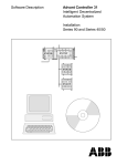
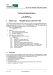
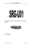
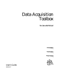
GPI Install Guide
_____________________________________________________________________
Contents
Windows 2000
PCI GPI- 8 or PCI GPI-16 Install
-2
Windows NT
PCI GPI-8 or PCI GPI-16 Install
-4
Windows XP
PCI GPI8 or PCI GPI16 Install
-6
Other GPI Devices
USB GPI8 Install
USB GPI8/8 Install
Serial SRC32 Install
ISA GPI Install (8 & 16) (NT & 2000)
-8
-9
-10
-12
Wiring Info
General Wiring Example
GPI8 Pin Layout
GPI16 Pin Layout
USB GPI 8 Pin Layout
SRC 32 Pin Layout
-14
-15
-16
-17
-18
1
GPI Install Guide
_____________________________________________________________________
PCI GPI-8 or GPI-16 Install for Windows 2000
A GPI-8 card will have a heavy gray cable with a molded female 37-pin
connector.
The GPI-16 uses the same instructions except where noted within the guide.
A GPI-16 will have two flat ribbon cables that attach to the card and
pass through a slot, out the back of the computer.
The connector port closest to the slot on the card is for GPI/O 1-8
while the connector in the middle of the card is for GPI/O 9-16.
Here are the steps for installing a PCI GPI-8 or PCI GPI-16 card in Windows 2000
Professional.
IMPORTANT: One should check the BIOS of the machine for the option:
PLUG and PLAY OS = YES/NO.
This option should be set to NO. If the computer BIOS does not have this option, one
might not be able to get the PCI GPI card to function. In this case, one should consider
using a USB based GPI device.
1. Shut down the PC and install the card into an available PCI slot. Once the card has
been installed, re-power up the PC.
2. Go to the START menu. Select PROGRAMS>ADMINISTRATIVE
TOOLS>COMPUTER MANAGEMENT.
3. Under the DEVICE MANAGEMENT section there should be a device with a “?” in
front of it. RIGHT-CLICK on the device and select PROPERTIES.
4. Select the RESOURCES tab. This should display two I/O
addresses.
Use the lower left-hand address range
NOTE: If the card does not respond after the
installation is finished, repeat the process using
the upper left-hand address range.
5. Close the Device Properties screen and the Computer
Management Screen and open the COMMAND PROMPT.
6. Type CD \ (This should give a C:\ prompt)
7. Type and enter: CD DAD\DRIVERS.NT\GPI
As of DAD version 5.0+ the path to enter is: CD DAD\DRIVERS\GPI
2
GPI Install Guide
_____________________________________________________________________
8. Type and enter: EDIT DADPIO.INI
9. Find the line:
IoPortAddress = REG_DWORD 0X00000300
Change the last four digits of the line to the address found in the above steps.
For example: IoPortAddress = REG_DWORD 0X0000A000
GPI-16 NOTE:
For a GPI-16 one must also modify the line:
IoPortCount = REG_DWORD 0x00000004
Change the last digit of the line to ‘8’
For example: IoPortCount – REG_DWORD 0x00000008
10. Save and exit this file.
11. From the DOS Prompt again, Type AUTOINST C:\DAD then hit <ENTER>.
This will flash; then close the window.
12. Start up DAD. After DAD has loaded. Go to SETUP and then select CFI & README
and open the workstation’s CFI file. (Top left button in white)
13. Scroll down towards the bottom of the file and find the line REMOTE = 0.
Modify this line to: REMOTE = PCI “Your Address” oicx
(Example) REMOTE = PCI A000 oicx
GPI-16 NOTE:
If a GPI-16 is being installed, one should modify this line to:
REMOTE = PCI “Your Address” oicxoicx
(Example) REMOTE = PCI A000 oicxoicx
14. Find the line GPO_GPI = 0 0 0 and change it to GPO_GPI = 8 8 16
GPI-16 NOTE:
If a GPI-16 is being installed, one should modify this line to:
GPO_GPI = 16 16 32
15. Save the changes and close the file. Hit the yellow REFRESH Button, then EXIT
DAD. Once DAD has exited, reboot the PC.
To test the card, start DAD, open the LIBRARY, open the COMMAND window and type
the line PULSE GPO 1 1000 and hit EXECUTE. This will send a relay from DAD to
GPO 1. One should be able to hear a “click” on the card itself when the relay opens,
then closes.
If you would like an Install file to prevent Windows from wanting to install a ‘New Device’ you can
use and install the following INF file
ftp://ftp.enco.com/pub/drivers/GPI/CBI95.INF
3
GPI Install Guide
_____________________________________________________________________
PCI GPI-8 or GPI-16 Install for Window NT
Here are the steps for installing a PCI GPI-8 or a GPI-16 in Windows NT.
NOTE: The GPI card should be physically installed after the Instacal software has been
installed on the workstation.
1. Install the Instacal Software that was provided with the card. If the software is not
available, it can be downloaded at:
http://www.computerboards.com/download.htm
2. Shutdown the PC and install the PCI GPI-8 or GPI-16 card into an available PCI
slot. Restart the machine after the card has been installed.
3. Run the Instacal program.
[START>PROGRAMS>COMPUTER BOARDS>INSTACAL]
The program will find the new card.
4. Double-click on the new card it has found. It will display an
IO address on the left-hand side in a grayed out box. Make
note of the address, then close the Instacal program.
5. Open the COMMAND PROMPT and enter CD \ (This will
take you to the C:\ prompt)
6. Type and enter: CD DAD\DRIVERS.NT\GPI
As of DAD version 5.0+ the path to enter is: CD DAD\DRIVERS\GPI
7. Type and enter: EDIT DADPIO.INI
8. Find the line (tenth from the top)
IoPortAddress = REG_DWORD 0X00000300
Change the last four digits of the line to the address found in the above steps.
For example: IoPortAddress = REG_DWORD 0X0000A000
GPI-16 NOTE:
For a GPI-16 one must also modify the line:
IoPortCount = REG_DWORD 0x00000004
Change the last digit of the line to ‘8’
For example: IoPortCount – REG_DWORD 0x00000008
9. Save and exit this file.
10. From the DOS Prompt again, type and enter: AUTOINST C:\DAD
This will flash then close the window
11. From CONTROL PANEL, select and run the DEVICES icon.
12. Scroll down the list and find “Computer Boards Data Acquisition” Highlight that line
and hit the STARTUP button to the right of it. Select the DISABLE option then OK.
Close the Devices window and Control Panel.
4
GPI Install Guide
_____________________________________________________________________
13. Start up DAD. After DAD has loaded. Go to SETUP and select CFG & README.
Open the workstation’s CFG file. (Top left button in white)
14. Scroll down towards the bottom of the file and find the line REMOTE = 0.
Modify this line to: REMOTE = PCI “Your Address” oicx
(Example) REMOTE = PCI A000 oicx
GPI-16 NOTE:
If a GPI-16 is being installed, one should modify this line to:
REMOTE = PCI “Your Address” oicxoicx
(Example) REMOTE = PCI A000 oicxoicx
15. Find the line GPO_GPI = 0 0 0 and change it to GPO_GPI = 8 8 16
GPI-16 NOTE:
If a GPI-16 is being installed, one should modify this line to:
GPO_GPI = 16 16 32
16. Save the changes and close the file. Hit the yellow REFRESH Button, then EXIT
DAD. Once DAD has exited, reboot the PC.
To test the card, start DAD, open the LIBRARY, open the COMMAND window and type
the line PULSE GPO 1 1000 and hit EXECUTE. This will send a relay from DAD to
GPO 1. One should be able to hear a “click” on the card itself when the relay opens,
then closes.
5
GPI Install Guide
_____________________________________________________________________
PCI GPI-8 or GPI-16 Install for Windows XP
Here are the steps for installing a PCI GPI-8 or a GPI-16 in Windows XP.
NOTE: The GPI card should be physically installed after the Instacal software has been
installed on the workstation.
1. Install the Instacal Software that was provided with the card. If the software is not
available, it can be downloaded at:
http://www.computerboards.com/download.htm
2. Shutdown the PC and install the PCI GPI-8 or GPI-16 card into an available PCI
slot. Restart the machine after the card has been installed.
3. Microsoft Windows will automatically detect the card and start the Install Wizard.
Allow the Install Wizard to automatically detect the card. Follow the prompts for the
Wizard until finished.
4. After the Wizard has completed, run the Instacal program.
[START>PROGRAMS>COMPUTER BOARDS>INSTACAL]
The program will find the new card.
5. Double-click on the new card it has found. It will display an
IO address on the left-hand side in a grayed out box. Make
note of the address, then close the Instacal program.
6. Open the COMMAND PROMPT and enter CD \ (This will
take you to the C:\ prompt)
7. Type and enter: CD DAD\DRIVERS.NT\GPI
As of DAD version 5.0+ the path to enter is: CD DAD\DRIVERS\GPI
8. Type and enter: EDIT DADPIO.INI
9. Find the line (tenth from the top)
IoPortAddress = REG_DWORD 0X00000300
Change the last four digits of the line to the address found in the above steps.
For example: IoPortAddress = REG_DWORD 0X0000A000
GPI-16 NOTE:
For a GPI-16 one must also modify the line:
IoPortCount = REG_DWORD 0x00000004
Change the last digit of the line to ‘8’
For example: IoPortCount – REG_DWORD 0x00000008
10. Save and exit this file.
11. From the DOS Prompt again, type and enter: AUTOINST C:\DAD
This will flash then close the window
12. Uninstall the Computer Board software. This is done from START > SETTINGS >
6
GPI Install Guide
_____________________________________________________________________
CONTROL PANEL > Add/Remove Programs.
13. Start up DAD. After DAD has loaded. Go to SETUP and select CFG & README.
Open the workstation’s CFG file. (Top left button in white)
14. Scroll down towards the bottom of the file and find the line REMOTE = 0.
Modify this line to: REMOTE = PCI “Your Address” oicx
(Example) REMOTE = PCI A000 oicx
GPI-16 NOTE:
If a GPI-16 is being installed, one should modify this line to:
REMOTE = PCI “Your Address” oicxoicx
(Example) REMOTE = PCI A000 oicxoicx
15. Find the line GPO_GPI = 0 0 0 and change it to GPO_GPI = 8 8 16
GPI-16 NOTE:
If a GPI-16 is being installed, one should modify this line to:
GPO_GPI = 16 16 32
16. Save the changes and close the file. Hit the yellow REFRESH Button, then EXIT
DAD. After DAD has been exited, restart the computer.
17. To test the card, start DAD, open the LIBRARY, open the COMMAND window and
type the line PULSE GPO 1 1000 and hit EXECUTE. This will send a relay from
DAD to GPO 1. One should be able to hear a “click” on the card itself when the relay
opens, then closes.
7
GPI Install Guide
_____________________________________________________________________
USB GPI-8 Install for Window 2000 or Windows XP
The USB GPI-8 can be used by machines that lack an available PCI slot
or can not utilize a PCI GPI because of BIOS limitations.
NOTE: Support for these units was added in DAD 4.2k28 (Jun.06.03)
Here are the steps for installing a USB GPI-8 in Windows 2000 or
Windows XP
1. Install the Switch and Sense software. If the software is not available, it can be
downloaded from the FTP site:
ftp://ftp.enco.com/pub/drivers/GPI/USB/Switch&Sense8.zip
2. After the software has been installed, physically connect the USB GPI-8 to the
workstation and power the USB device.
3. Go to START > PROGRAMS > COMPUTER BOARDS and run
the Switch & Sense 8 software. This MUST be run once with
the user clicking on a relay at least one time.
NOTE: This MUST happen before DAD will see the USB
device.
4. Start up DAD. After DAD has loaded. Go to SETUP and select
CFG & README. Open the workstation’s CFG file.
5. Scroll down towards the bottom of the file and find the line REMOTE = 0.
Modify this line to: REMOTE = CBUSB8
Also modify the line GPI_GPO = 8 8 16
6. Save the changes and close the file. Hit the yellow REFRESH Button, then EXIT
DAD. Once DAD has exited, reboot the PC.
To test the card, start DAD, open the LIBRARY, open the COMMAND window and type
the line PULSE GPO 1 1000 and hit EXECUTE. This will send a relay from DAD to
GPO 1. One should be able to hear a “click” on the unit itself when the relay opens,
then closes.
Other notes:
If a different unit has been plugged into a pre-configured
DAD workstation, the application will say there is a unit on 0
and 1. One should delete the unit on 0 (select the unit and
press the big red X). After doing this reboot the workstation.
When the workstation reboots, go back into the application
and Test a relay. Now DAD will talk to the new unit.
8
GPI Install Guide
_____________________________________________________________________
USB GPI-8/8 Install for Window 2000 or Windows XP
[ ! ]This USB device is an update physical unit to the older USB-8
described above. Please verify that the unit is an USB 8/8 device before
installing.
NOTE: Support for these units was added in DAD 5.1.D (Sep.06)
Here are the steps for installing a USB GPI-8 in Windows 2000 or Windows XP
1. Install the Instacal Software that was provided with the card. If the software is not
available, it can be downloaded at:
http://www.computerboards.com/download.htm
2. After the software has been installed, physically connect the
USB GPI-8 to the workstation and power the USB device.
3. Go to START > PROGRAMS > MEASUREMENT
COMPUTING and run InstaCal. Select your board and run a
test, the Relay Noise Test works great.
NOTE: This MUST happen before DAD will see the USB
device.
4. Start up DAD. After DAD has loaded. Go to SETUP and
select CFG & README. Open the workstation’s CFG file.
5. Scroll down towards the bottom of the file and find the line REMOTE = 0.
Modify this line to: REMOTE = UNIVERSAL
Also modify the line GPI_GPO = 8 8 16
6. Save the changes and close the file. Hit the yellow REFRESH Button, then EXIT
DAD. Once DAD has exited, reboot the PC.
To test the card, start DAD, open the LIBRARY, open the COMMAND window and type
the line PULSE GPO 1 1000 and hit EXECUTE. This will send a relay from DAD to
GPO 1. One should be able to hear a “click” on the unit itself when the relay opens,
then closes.
Other notes:
If a different unit has been plugged into a pre-configured
DAD workstation, the application will say there is a unit on 0
and 1. One should delete the unit on 0 (select the unit and
press the big red X). After doing this reboot the workstation.
When the workstation reboots, go back into the application
and Test a relay. Now DAD will talk to the new unit.
9
GPI Install Guide
_____________________________________________________________________
BT SRC32 Install for Window 2000 or Windows XP
The Broadcast Tools SRC32 unit allows one to use an
expandable GPI/O interface with DAD.
NOTE: Support for these units was added in DAD 4.2k28
(Jun.06.03)
Here are the steps for installing a serial BT-SRC32 unit for use with DAD.
Configuration of DAD:
Start up DAD. After DAD has loaded, go to SETUP and select CFG & README. Open
the workstation’s CFG file.
Scroll down towards the bottom of the file and find the following lines, modifying them
as such:
COM2_INFO = "38400 N 8 1"
REMOTE = BTSRC32 2
REMOTE_PROCESS_DELAY = 0
GPO_GPI = 32 32 64
GPI_REVERSE_SENSE = ON
NOTE: This guide is using Com Port 2. If you are using a different Com Port, please
adjust the COMx_INFO line and the REMOTE line accordingly. For example:
Comx_INFO is: Com<port number>_INFO = "38400 N 8 1"
REMOTE is: REMOTE = BTSRC32 <port number>
Save the changes and close the file. Hit the yellow REFRESH Button, then EXIT DAD.
Once DAD has exited, reboot the PC.
Configuration of the BTSRC32 unit:
Inside the SRC32 unit one must set the Dip Switch accordingly. [0=off / 1=on]
12345678
On
xxx x
Off
xx
xx
Notes on Dip Switch options
Switch
Setting
1&2
0 0 = unit 0
(master)
0 1 = unit 1
1 0 = unit 2
1 1 = unit 3
3&4
0 0 = 9600
0 1 = 2400
1 0 = 19200
1 1 = 38400
5
On =
Hex
Off =
ASCII
6
On = Pair
Off= normal
7
Modem mode
not supported
8
invert LCD display status
On = [closed=1 / open=0]
Off = [closed=0 / open=1]
One must also change the internal jumper number 13 from EXTERNAL to RS232.
Failure to do so could result in the ability to use GPI's but NOT the ability to use GPO's.
10
GPI Install Guide
_____________________________________________________________________
Other Notes:
When using more than one unit, one must set the dip switches on each unit
accordingly. DAD MUST talk to the unit that is defined as the Master (unit 0). The sync
cable between the units must be connected to the EXT2 on the master and connected
to the EXT1 on the slave unit.
Also, one must remember to modify the DAD workstation CFG file to reflect the proper
amount of inputs and outputs.
For example: GPO_GPI = 64 64 128
IMPORTANT:
If one has followed all instructions above and can not get the unit to function properly,
there is a chance that one MIGHT have to install the DADPIO with the default address.
For example, run the C:\DAD\DRIVERS\AutoInst.BAT file
This will install the DADPIO with the default address of 300.
11
GPI Install Guide
_____________________________________________________________________
ISA GPI-8 or GPI-16 Install for Windows NT or Windows 2000
A GPI-8 card will have a heavy gray cable with a molded female 37-pin
connector.
The GPI-16 uses the same instructions except where noted within the guide.
A GPI-16 will have two flat ribbon cables that attach to the card and
pass through a slot, out the back of the computer.
The connector port closest to the slot on the card is for GPI/O 1-8 while
the connector in the middle of the card is for GPI/O 9-16.
Here are the steps for installing an ISA GPI-8 or ISA GPI-16 card in Windows 2000.
IMPORTANT: One will need to set either the ISA slot or an IRQ within BIOS of the
machine to LEGACY. If one can not set this option, one will not be able to utilize the
ISA card within the operating system.
1. Open the COMMAND PROMPT.
Type and Enter: CD \ (This should give a C:\ prompt)
2. Type CD DAD\DRIVERS.NT\GPI then hit <ENTER>.
3. Type EDIT DADPIO.INI then hit <ENTER>.
4. Find the line (third from the bottom)
IoPortCount = REG_DWORD 0x00000004
For a GPI8, leave this line alone. Go to step 6.
GPI16 NOTE:
For a GPI16, change this line as shown below:
IoPortCount = REG_DWORD 0x00000008
5. Save and Exit this file.
6. From the DOS Prompt again, Type AUTOINST C:\DAD then hit <ENTER>.
This will flash then close the window.
7. Start up DAD.
8. After DAD has loaded. Go to SETUP and select README.
9. Open the workstation’s CFG file. (Top left button in white)
10. Towards the bottom of the file, find the line REMOTE = 0.
Change this line to read: REMOTE = 300
Also, find the line GPO_GPI = 0 0 0 and change it to GPO_GPI = 8 8 16
GPI16 NOTE:
For a GPI 16, set the line to: GPO_GPI = 16 16 32
12
GPI Install Guide
_____________________________________________________________________
11. Save the changes and close the file close. Hit the yellow REFRESH Button, then
EXIT DAD.
12. Reboot the PC.
13. The GPI card should now be configured. To test the card, start DAD, open the
LIBRARY, open the COMMAND window and type the line PULSE GPO 1 1000 and
hit EXECUTE. This will send a relay from DAD to GPO 1. One should be able to
hear a “click” on the card itself when the relay opens, then closes.
13
GPI Install Guide
_____________________________________________________________________
GPI8 Wiring Info
The following is a diagram for the pin layout of a GPI8.
Satellite Receiver
Interconnection To DAD
DAD GPI Inputs
27
GPI 1
8
Satellite Receiver Contact Closures Provided By Cue/Tone Decoders
26
GPI 2
7
25
GPI 3
6
24
GPI 4
5
23
GPI 5
4
22
GPI 6
3
21
GPI 7
2
20
GPI 8
1
Supply
Voltage
NOTE: Supply voltage can be 5 - 30 volts AC or DC.
IMPORTANT: The card manufacture refers to the inputs and output as 0-7. DAD refers
to the inputs and output as 1-8. For example: the card’s pin out for Input 5 would be
referred to GPI 6 in DAD.
14
GPI Install Guide
_____________________________________________________________________
GPI8 Pin Layout
The following is a Pin Layout Diagram of a GPI8 card.
IMPORTANT: The card manufacture refers to the inputs and output as 0-7. DAD refers
to the inputs and output as 1-8. For example: the card’s pin out for Input 5 [pins 3 and
22] would be referred to GPI 6 in DAD.
15
GPI Install Guide
_____________________________________________________________________
GPI16 Pin Layout
The following is a Pin Layout Diagram of a GPI16 card.
IMPORTANT: The card manufacture refers to the inputs and output as 0-7. DAD refers
to the inputs and output as 1-8. For example: the card’s pin out for Input 5 [pins 5 and
6] would be referred to GPI 6 in DAD.
16
GPI Install Guide
_____________________________________________________________________
USB GPI 8 Pin Layout
The following is a Pin Layout Diagram of a USB GPI 8.
IMPORTANT: The manufacture refers to the inputs and output as 0-7. DAD refers to
the inputs and output as 1-8. For example: the device pin out for Input 5 [pins IP5A and
IP5B] would be referred to GPI 6 in DAD.
17
GPI Install Guide
_____________________________________________________________________
BT SRC32 Pin Layout
The following is a Pin Layout Diagram of a BT SRC32.
IMPORTANT: The manufacture refers to the inputs and output as 1-32. DAD refers to
the inputs and output as 1-32. For example: the device pin out for Input 5 [Screws
Bottom-1 In-5a and Bottom-1 In-5b] would be referred to GPI 5 in DAD.
18