1
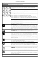
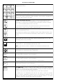
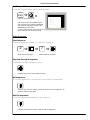
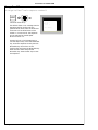
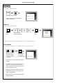
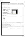
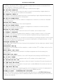
User Manual for SYSTEM 500M
SYSTEM 500M User Manual - Rev. 4.1
Table of Contents:
Keyboard types
3
Legends Used
3
Key Functions
4
Camera Select and PTZ-Camera Control
8
Select Camera
8
Select Camera for PTZ-Control
8
Take PTZ-Control
9
Zoom
9
Focus
9
Iris
9
Pan Camera
10
Tilt Camera
10
Auto panning
10
Call Preposition
11
Sequence prepositions
11
Remove text
11
Activate auxiliary function
11
De-activate auxiliary function
11
Monitor Operation and Time/Date
12
Select Monitor
12
Blank Monitor
12
Default Monitors
12
Display Time and Date
12
Set Time and Date
13
Video Sequence
13
Start Sequence
13
Step fast through a sequence
13
Hold sequence
13
Hold all sequences
13
Change Dwell Time
14
Alarm Operation
15
Clear Alarm
15
Clear Alarm in another group
15
Alarm Status
16
Alarm Status
16
Password
16
Active Alarms
16
Alarm Zones
17
Alarm Input
17
Number 2822-00025
GB - Page 1
User Manual for SYSTEM 500M
Operation of Adpro equipment
Setting the Keyboard Access Level
18
Take Adpro control
18
Adpro functions
18
Programming the Adpro equipment
18
Operation of Integrated Camera Unit (ICU)
GB - Page 2
18
19
Auto focus
19
Auto iris
19
Back Light Compensation
19
Macro playback
20
Error Messages
21
Keyboards 1500M and 1502M layouts
25
Keyboards 1501M and 1503M layouts
27
Number 2822-00025
User Manual for SYSTEM 500M
Keyboard types
Five different keyboard types can be used to control the SYSTEM 500M:
Keyboard 1500M: Arrow keys for Pan/Tilt, no display, one shared RS232/RS485 port, no
Adpro control keys, no ICU control keys
Keyboard 1501M: Joystick for Pan/Tilt, no display, one shared RS232/RS485 port, no
Adpro control keys, ICU control keys, possibility for direct ICU/Camera Station control.
Keyboard 1502M: Arrow keys for Pan/Tilt, display, one shared RS232/RS485 port, ARC
NET port, Adpro control keys, ICU control keys, macro recording, possibility for direct
ICU/Camera Station control.
Keyboard 1503M: Joystick for Pan/Tilt, display, one shared RS232/RS485 port, ARC NET
port, Adpro control keys, ICU control keys, macro recording, possibility for direct
ICU/Camera Station control.
Front panel keyboard: This is the internal keyboard of the SYSTEM 500M, it has arrow
keys for Pan/Tilt, no Adpro control keys, no ICU control keys.
See page 25 and 27 for keyboard layouts
Legends Used
When two keys are used in a combination, i.e. typically the ESC key and another key, the first
key is depressed and released again before the second key is depressed. The second key should
be activated within approximately 2 seconds after the first key is released. This procedure is
basically equal to the normal key strokes when selecting cameras etc.
This method is illustrated by using an "→ " sign between the two keys, refer to the example
below:
ESC
ð
Set the time and date
Number 2822-00025
GB - Page 3
User Manual for SYSTEM 500M
Key Functions
The keys on the keyboard have the following functions:
KEY
DESCRIPTION
7
8
9
4
5
6
1
2
3
ESC
0
CLR
The numeric keys are used to select the ID numbers of the monitors and cameras
connected to the system, as well as video sequences, camera prepositions and
remote sites.
The CLR key resets all digits in the status display to 0 (zero).
The CLR key is also used to clear any message displayed on the monitors, except for
the camera text string and alarm messages.
The ESC key is in non-programming mode used for the following purposes:
The key combination ESC → DISPLAY TIME give access to adjustment of the clock.
The key combination ESC → CLEAR ALARM display the alarm status menu.
The key combination ESC → MONITOR set all monitors to default.
The key combination ESC → SEQUENCE accesses the sequence dwell time factor.
The key combination ESC → PREPOSITION will together with the numerical keys
save a preposition.
The ESC key itself is, when Adpro equipment is controlled, used to activate the
Adpro function "END".
The key combination ESC + ↑/↓ is used in connexion with the Adpro VST 10CA to
make CHANNEL UP/DOWN selections.
The key combination ESC + ←/→ is used in connexion with the Adpro VST 10CA to
make DISPLAY LEFT/RIGHT selections.
The MONITOR key is used to select a monitor. If monitor No. 1 is to be selected,
press the numeric key "1", and immediately after the key "MONITOR". The
MONITOR key is also used in order to give control over a selected camera. When the
camera has been selected make sure that the status display on the keyboard shows
"0000" and then press the MONITOR key that makes it possible to control this
camera.
The CAMERA key is used to select a camera. If camera No. 1 is to be selected,
press the numeric key "1", and immediately after the key "CAMERA".
The SEQUENCE key is used to select a sequence. If sequence No. 1 is to be
selected, press the numeric key "1", and immediately after the key "SEQUENCE".
The SEQUENCE key is also used to step fast through a sequence, every time the
SEQUENCE key is pressed the sequence will go to the next camera.
The SEQUENCE key is ALSO used to start a pre-programmed sequence of the
camera positions. This function can only be used if Ernitec Preposition Camera
Stations are connected.
The HOLD key is used to stop the SEQUENCE function temporary.
Press once and the sequence stops on the currently selected monitor. Press HOLD
once more and the sequence will start again.
Press and hold down the HOLD key in order to stop all running sequences.
The DISPLAY TIME key is pressed to display TIME and DATE on the monitor.
Pressing the key a second time, TIME and DATE is removed from the monitor.
Used together with the ESC key to get access to adjustment of the clock: If the
time/date should be reset, press the key "ESC", and immediately after the key
"DISPLAY TIME".
?
The HELP key is used display/remove text displayed by the selected Camera Station.
This function can only be used if BDR-55X Camera Stations are used.
In Adpro control, the HELP key is used to display help menus, if any.
The CLEAR ALARM key is used to clear an alarmed picture from the monitor.
Pressing the ESC key immediately followed by the CLEAR ALARM key will access
the ALARM STATUS MENU.
GB - Page 4
Number 2822-00025
User Manual for SYSTEM 500M
The DISPLAY TEXT key is used to remove or insert text displayed by the selected
Camera Station. Pressing the key ones removes text. Pressing the key again inserts
the text. This function can only be used if BDR-55X Camera Stations are used.
A
The arrow keys are used for manual control of a pan and tilt unit.
Only available for cameras controlled by Ernitec Camera Stations.
The key combination ESC + ↑/↓ is used in connexion with the Adpro VST 10CA to
make CHANNEL UP/DOWN selections.
The key combination ESC + ←/→ is used in connexion with the Adpro VST 10CA to
make DISPLAY LEFT/RIGHT selections.
The PREPOSITION key is used together with the numeric keys, in order to call a
preposition. If preposition number 45 should called, press the numerical keys
"4""5", and immediately after the key "PREPOSITION". Pressing the ESC key
immediately followed by the PREPOSITION key is used to save a preposition to the
number entered in front of this key combination.
These functions can only be used if ERNITEC Preposition Camera Stations, are
connected.
The AUTO key is used together with the focus/iris keys to switch the ICU back into
Auto Focus, and/or Auto Iris
AUTO
The two ZOOM keys are used to change the focal length of the lens, and
consequential the view angle of the camera.
Only available for cameras controlled by Ernitec Camera Stations.
The two FOCUS keys are used to bring into focus the part of the scene observed.
Only available for cameras controlled by Ernitec Camera Stations.
ICU: When pressed the ICU enters manual focus mode
The IRIS keys are used to adjust the iris opening, to compensate for varying light
conditions on the scene observed.
Only available for cameras controlled by Ernitec Camera Stations.
ICU: When pressed the ICU enters manual iris mode
1
2
3
4
5
6
The six AUX keys are intended for user selected functions. The AUX functions are
typically used for control of light, washer, wiper and gates.
Only available for cameras controlled by Ernitec Camera Stations.
Number 2822-00025
GB - Page 5
User Manual for SYSTEM 500M
F1 F2 F3
The F1 and F2 keys can be used to control a relay or open collector output directly,
if programmed to do so.
F4 F5 F6
F7 F8 F9
F10 F11
AUX
AUX
VCR
1
VCR
2
The MENU key calls the main programming menu and can be used to exit the setup
system while saving any programming changes made.
If Adpro equipment currently is being controlled the MENU key will call the setup
menu on the Adpro equipment being controlled. This function corresponds to
MENU
activate the Adpro function key "END".
The AUX ON and AUX OFF keys are used to control the corresponding auxiliary
relays 1-6 in the camera stations Series BDR-500. If the auxiliary relay 3 in the
camera station currently being controlled should be activated, press the numerical
key "3", and immediately after the key "AUX ON".
The AUX keys are intended for user selected functions. The AUX functions are
typically used for control of light, washer, wiper and gates.
The VCR1 and VCR2 keys can be used to control a relay or open collector output
directly, if programmed to do so.
These outputs are typically used to manually control a video cassette recorder, since
the same outputs can be activated automatically in alarm situations, if programmed
to do so.
The MACRO key is together with the numerical keys used to play back a macro. If
macro number 45 should be played back, press the numerical keys "4""5", and
immediately after the key "MACRO".
The SITE key is used to select a site. If site No. 2 is to be selected, press the
numerical key "2", and immediately after the key "SITE".
Note: The site selection feature is available from keyboards connected to the
ARC-net only.
The BACK LIGHT COMPENSATION key is used in connexion with the ICU to
enable/disable the cameras Back light compensation.
SHIFT
DEL
The SHIFT key is used in combination with the 'DELETE' and 'INSERT' keys, refer to
the Camera Station manual for more information.
The DELETE key is used to delete prepositions from the preposition stack, refer to
the Camera Station manual for more information.
Only used in combination with Ernitec preposition Camera Stations.
INS
The INSERT key is used to insert prepositions in the preposition stack, refer to the
Camera Station manual for more information.
Only used in combination with Ernitec preposition Camera Stations.
ADPRO
The ADPRO key is used in order to give control over the Adpro equipment
associated or connected with the selected camera. Pressing the ADPRO key makes it
possible to control the associated Adpro equipment.
Pressing the key a second time will disable control to the Adpro equipment.
The ADPRO key is in combination with the ESC key used to enter the operator
LEVEL1 or LEVEL 2 passwords: Pressing the ESC key immediately followed by the
ADPRO key will allow the operator to enter the required password. For further
information, refer to the specific section later in this manual.
GB - Page 6
Number 2822-00025
User Manual for SYSTEM 500M
The PHONE key is used in connexion with the VST 10CA Fast Scan to display the list
of phone numbers, select a phone number and dial up.
The AUDIO key is used in connexion with the VST 10CA Fast Scan to enable audio
transmission from the transmitter site to the receiver site. Pressing the AUDIO key a
second time will disable the audio transmission again.
Pressing the ESC key immediately followed by the AUDIO key will enable audio
transmission in the opposite direction, i.e. from the receiver site to the transmitter
site. Pressing this key combination a second time will disable the audio transmission.
The audio quality can be selected by pressing the numerical keys 1, 2, or 3 in front
of the AUDIO key.
The QUAD key is used in connexion with the VST 10CA Fast Scan to set the video
display in quad mode. Pressing the key a second time will toggle the display mode
back to full screen.
The ENHANCE key is used in connexion with the VST 10CA Fast Scan to toggle
between two predefined display resolutions. It is also possible to directly specify the
picture resolution by pressing a numerical key in the range of 1 to 8 in front of the
ENHANCE key.
ON
OFF
The CONTROL ON/OFF keys is used in connexion with the VST 10CA Fast Scan to
control the corresponding control outputs 1-10 on the Fast Scan located at the
transmitter site. If the control output 3 should be activated, press the numerical key
"3", and immediately after the key "CONTROL ON".
The ten control outputs are intended for user selected functions such as lights,
washer, wiper and gates.
The MODE 1/2 key is used in connexion with the VM-12 Video motion detection
modules fitted in the VMD-10 rack frame to select the mode of operation between
two pre-programmed setup's. If operating mode 2 should be selected on the VM-12
module currently being controlled, press the numerical key "2", and immediately
after the key "MODE 1/2".
MODE
1/2
The DETECTION ON and DETECTION OFF keys are used in connection with the
VM-12 Video motion detection modules fitted in the VMD-10 rack frame to select
the DETECTION mode.
For further information refer to the Adpro VMD-10 Manual.
DET
ON
DET
OFF
Second key
functions F1 - F12
The DETECTION ON and DETECTION OFF keys are used in connection with the
VM-12 Video motion detection modules fitted in the VMD-10 rack frame to select
the DETECTION mode.
For further information refer to the Adpro VMD-10 Manual.
These keys are used only during setup of the keyboard; refer to the keyboard
manual or the SYSTEM 500M Programming Manual.
Number 2822-00025
GB - Page 7
User Manual for SYSTEM 500M
Camera Select and PTZ-Camera Control
The PTZ functions listed below are also available for PTZ cameras remotely connected to the
VST 10CA Fast Scan transmitters; refer to the Operation section in the VST 10CA Manual
Select Camera
If Camera 3 is to be displayed on Monitor number 1 (SYSTEM 500M only):
1 ð
ð 3 ð
3 ð
SYSTEM 500M
Select monitor number 1
VST 10CA
Select camera number 3
Select channel number 3
Select Camera for PTZ-Control
If Camera 4 is to be displayed and controlled on Monitor number 2:
2 ð
Select monitor number 2
ð 4 ð
Select camera number 4
Note:*
ð
Take
control
Note:*
Note*: The MON key should not be used in connection with cameras connected to the VST
10CA, since monitor operation is disabled while controlling Adpro equipment. Cameras
connected to the VST 10CA can be PTZ-operated when displayed without further key strokes.
GB - Page 8
Number 2822-00025
User Manual for SYSTEM 500M
Take PTZ-Control*
To control the PTZ functions on a camera present on the monitor selected by this keyboard:
Take control*
Warning*: The MON key should not be used in connection with cameras connected to the
VST 10CA, since monitor operation is disabled while controlling Adpro equipment. Cameras
connected to the VST 10CA can be PTZ-operated when displayed without further key strokes.
Zoom
Change the focal length:
1500M/1502M
1501M/1503M
1500M/1502M
Zoom wide
1501M/1503M
Zoom narrow
Focus
If the picture on the selected monitor is not in focus, press:
Focus near
Focus far
NOTE: When controlling an Integrated Camera Unit (ICU), pressing
one of the focus keys will switch the ICU into manual focus mode.
Iris
If the picture on the monitor is too dark or light, press:
Iris open
Iris close
NOTE: When controlling an Integrated Camera Unit (ICU), pressing
one of the iris keys will switch the ICU into manual iris mode.
Number 2822-00025
GB - Page 9
User Manual for SYSTEM 500M
Pan Camera
If the camera should be panned left or right, press:
1500M/1502M
1501M/1503M
1500M/1502M
Pan left
1501M/1503M
Pan right
JOYSTICK NOTE: When controlling a variable speed Pan/tilt, BDR-575 or ICU, pushing the
joystick towards its extremes will increase speed.
Tilt Camera
If the camera should be tilted up or down, press:
1500M/1502M
1501M/1503M
1500M/1502M
Tilt up
1501M/1503M
Tilt down
JOYSTICK NOTE: When controlling a variable speed Pan/tilt, BDR-575 or ICU, pushing the
joystick towards its extremes will increase speed.
Auto panning (only BDR-575 & ICU)
To start auto panning, press:
AUTO
ð
Start auto panning
GB - Page 10
Number 2822-00025
User Manual for SYSTEM 500M
Call Preposition
To call preposition number 3, press:
3 ð
Call preposition number 3
Sequence prepositions
To start sequence prepositions on the currently controlled camera, press:
Sequence prepositions
Remove text
Remove the text generated by the currently controlled Camera Station:
A
?
Front panel
150XM
Remove or Insert text from camera station
Activate auxiliary function
Activate an auxiliary relay in the currently controlled Camera Station:
2
Front panel
2 ð
AUX
150XM
Activate AUX relay 2
De-activate auxiliary function
De-activate an auxiliary relay in the currently controlled Camera Station:
2
Front panel
2 ð
AUX
150XM
De-activate AUX relay 2
Note: Only when the AUX relays are latched
Number 2822-00025
GB - Page 11
User Manual for SYSTEM 500M
Monitor Operation and Time and Date
Note: If one of the following messages is shown on the keyboard display: VMD control
mode, VMF control mode or VST control mode the ADPRO key must be pressed in
order to leave this mode before monitor operation is possible.
Select Monitor
Select monitor number 2:
2 ð
Select monitor number 2
Blank Monitor
To blank the screen of monitor number 2:
2 ð
ð
Select monitor number 2
Blank monitor
Default Monitors
Set all monitors to the default camera or sequence:
ESC
ð
Set all monitors to default camera or sequence
Display Time and Date
To display current time and date on monitor number 2:
2 ð
Select monitor number 2
GB - Page 12
ð
Start the Time and Date function
Number 2822-00025
User Manual for SYSTEM 500M
Set Time and Date
To set the Time and Date, use the keys as shown:
ESC
ð
=
SET TIME/DATE
Call Time and Date set-up
DAY
: 00
MONTH : 00
Use the TILT UP or TILT DOWN keys to
find the item to set. Press the MONITOR
key, enter the new data and press the
MONITOR key once more.
Continue with the next item. Press the T/D
key to exit the Time and Date set-up.
YEAR
: 00
HOUR
: 00
MINUTE: 00
PRESS (T/D) TO SET
Video Sequence
Start Sequence
To display sequence number 7 on monitor number 2:
2 ð
Select monitor number 2
ð 7 ð
Select sequence number 7
Step fast through a sequence
To step fast through a sequence, press:
Press this key once for each sequence entry
Hold sequence
To hold the sequence on the monitor controlled by the keyboard:
Press this key once and release it again in order to stop the sequence. To
continue press this key again.
Hold all sequences
To hold all sequences displayed on any monitors:
Press and hold down this key in order to stop all sequences
Number 2822-00025
GB - Page 13
User Manual for SYSTEM 500M
Change Dwell Time
To change the Dwell Time for sequence number 8:
ESC
ð
=
START SEQUENCE
Call Dwell Time set-up
SEQ ID: 000
DWELL TIME
The default factor is 10, meaning that the
sequences will be running with the
specified dwell times; with the dwell time
factor set to 5 the dwell times will be
halved or, in other words, the sequence
will be executed at double speed.
Minimum factor is 3.
FACTOR:
00
(ESC) TO START SEQ
Use the TILT UP or TILT DOWN keys to
find the SEQ ID entry. Press the MONITOR
key, enter the sequence ID and press the
MONITOR key. Move down to the
FACTOR field and press the MONITOR key.
Enter the new factor and press the
MONITOR key. Press the ESC key to start
the sequence.
GB - Page 14
Number 2822-00025
User Manual for SYSTEM 500M
Alarm Operation
Clear Alarm
To clear a local alarm, press:
Removes the alarm present on the local alarm group monitor(s)
Clear Alarm in another group
To clear an alarm belonging to another alarm group. In this example the alarm to be cleared
belongs to group 2:
2 ð
Removes the alarm present on the alarm group 2 monitor(s)
Number 2822-00025
GB - Page 15
User Manual for SYSTEM 500M
Alarm Status
Alarm Status
Get access to alarm status:
ESC
ð
=
ALARM STATUS
Call Alarm Status menu
PASSWORD ( 4 DIGIT )
*
KEY IN YOUR 4 DIGIT PASSWORD
(Level 1 Password)
PRESS (ESC) TO QUIT
Password
Key in a 4 digit Password:
ð 0
Open
Field
0
0
0 ð
Enter Password
(Level 1 Password)
=
Close
Field
ALARM STATUS
*ACTIVE ALARMS
ALARM ZONES
ALARM INPUT
REMOTE ALARMS
PRESS (ESC) TO QUIT
The Alarm Status menu gives access to the following options:
Active Alarms
This sub-menu displays the alarms that are currently active.
ð
Move Cursor to
ACTIVE ALARMS,
using arrow keys,
or joystick.
=
Press MON to
call ACTIVE
ALARMS menu
ALARM STATUS GRP. *1
0
0
0
0
0
0
0
CLEAR ALL ALARMS
Use the keys 3 or 9 to view other Alarm
Groups.
Use the TILT UP or TILT DOWN keys, or
JOYSTICK, to position the cursor on an
alarm, and press the Clear Alarm key to
clear the selected alarm.
Pressing Clear Alarm while the cursor is
positioned at CLEAR ALL ALARMS, will
clear all listed alarms.
Press the ESC key to cancel the ACTIVE
ALARMS menu.
GB - Page 16
Number 2822-00025
User Manual for SYSTEM 500M
Alarm Zones
From this sub-menu it is possible to enable/disable Alarm Zones:
ð
Move Cursor to
ALARM ZONES,
using arrow keys,
or joystick.
=
ALARM ZONE STATUS
1: *ENABLED
2: ENABLED
3: ENABLED
4: ENABLED
5: ENABLED
6: ENABLED
7: ENABLED
8: ENABLED
Press MON to
call ALARM
ZONES menu
Use the TILT UP or TILT DOWN keys, or
JOYSTICK, to position the cursor on an
Alarm Zone, and press the MON key to
open the field. Use the PAN LEFT/RIGHT
keys, to select between Enabled and
Disabled, and press MON to close the
field and accept your selection.
Alarm Input
From this sub-menu it is possible to select whether the alarm inputs should be handled locally,
or send to a MAIN System:
ð
Move Cursor to
ALARM INPUT,
using arrow keys,
or Joystick
=
ALARM INPUT
ALARM INPUT IS:
*HANDLE LOCAL
Press MON to
call ALARM
INPUT menu
PRESS (ESC) TO QUIT
Press MON to open the field. Use the PAN
LEFT/RIGHT keys, or JOYSTICK, to select
between Handled Locally and Send To
MAIN, and press MON to close the field
and accept your selection.
Number 2822-00025
GB - Page 17
User Manual for SYSTEM 500M
Operation of Adpro equipment
The Adpro operating functions can only be accessed when the LEVEL 1 password is known
by the operator. In order to set-up the Adpro equipment the LEVEL 2 password is needed.
Note: The Adpro equipment can only be operated using 1502M/1503M keyboards.
Setting the Keyboard Access Level
In order to enter the Keyboard Access Level menu, press:
ESC
ð
ADPRO
=
KEYBOARD
ACCESS LEVEL
Set the keyboard Access level.
PASSWORD (4 DIGIT):
*
Press the MON key to activate the field,
and enter the password.
Terminate with the MON key again.
Press the CLR key to enter LEVEL 0 i.e. no
Adpro operation possible.
PRESS (CLR) TO ENTER
LEVEL 0
Take Adpro control
To control the Adpro functions on the camera currently present on the monitor selected by this
keyboard:
ADPRO
Take Adpro control
Adpro functions
The available Adpro functions are briefly described in the Key Functions section located
previously in this manual.
For a deeper description of the individual Adpro functions please refer to the Operation
section in the relevant Adpro Manuals.
Programming the Adpro equipment
During Adpro control mode press the MENU-key to enter the set-up system on the Adpro
equipment currently being controlled. Note, that this function requires that the keyboard has
access to LEVEL 2 functions.
For programming, please refer to the SETUP section of the relevant Adpro manual.
GB - Page 18
Number 2822-00025
User Manual for SYSTEM 500M
Operation of Integrated Camera Unit (ICU)
Some of the keys on the 1501M/1503M keyboards are reserved for special ICU functions.
Auto focus
In order to switch to auto focus, press:
AUTO
ð
or
AUTO
ð
Enable auto focus
The default setting after power-up is auto focus
Auto iris
In order to switch to auto iris, press:
AUTO
ð
or
AUTO
ð
Enable auto iris
The default setting after power-up is auto iris
Back light compensation
In order to enable/disable Back light compensation, press:
Back light compensation
ON/OFF
Number 2822-00025
GB - Page 19
User Manual for SYSTEM 500M
Macro playback
Macros can be recorded, and played back on the 1502M/1503M keyboards
In order to playback a macro:
8 ð
Playback macro number 8
If no macro has been assigned to the selected number, the following message is shown in the
keyboard display:
Macro empty.
For information on how to record macros, please refer to the Keyboard manual.
GB - Page 20
Number 2822-00025
User Manual for SYSTEM 500M
Error Messages
The SYSTEM 500M and/or the keyboards are able to display text messages for user guidance
only and as error messages.
Note: Certain error messages are displayed on monitor 1 only e.g. when downloading new
settings from the SYSTEM 500M Set-up program. It is therefore recommended to have a
camera displayed on the monitor 1 constantly.
ALARM OUT OF RANGE
The alarms are received on a serial RS-232 port from an external source according to the
Ernitec alarm protocol.
The actual alarm number received is invalid, valid range is 001-032
AUX # ON
Auxiliary function # has been activated.
AUX # OFF
Auxiliary function # has been de-activated.
AUX # OUT OF RANGE
The operator has on the keyboard entered an invalid AUX number - valid range is 1-6.
CAMERA ID NOT FOUND
An operator has tried to select a camera with an ID-number, which doesn't exist.
CAMERA IS FIXED
An operator has tried to PTZ-operate a camera, which in the matrix set-up is programmed as a
fixed camera.
CAMERA NOT VALID
An operator has tried to select a camera from a keyboard which is not allowed to access the
camera or has tried to display it on a monitor which is not allowed to display it.
INVALID KEY
The key the operator has pressed is programmed invalid for the current keyboard.
INVALID PREPOSITION
The entered preposition number is out of range, valid range is 1-128
Number 2822-00025
GB - Page 21
User Manual for SYSTEM 500M
KBD ## IN CONTROL
An operator has tried to PTZ- or Adpro-operate a camera which currently is operated from
another keyboard - keyboard number ##.
Try to override the other keyboard by pressing the MON-button again.
KBD ## USES MONITOR
An operator has tried to select a monitor which currently is selected by a keyboard with a
higher priority - the monitor is therefore not accessible.
KEY REQUIRE LEVEL #
The operator has pressed an Adpro key which is protected by a higher keyboard access level,
than the level currently available to the operator.
MON ## IN ALARM MODE
The operator has tried to select a camera or a sequence to a monitor on which an alarmed
picture is displayed.
MONITOR NOT VALID
The monitor is not accessible to the current keyboard.
MON XX IN SETUP MODE
The operator has tried to select a camera or a sequence to a monitor on which another
operator has entered the setup system.
MONITOR ID NOT FOUND
An operator has tried to select a monitor with an ID-number, which doesn't exist.
NO CONTROL POSSIBLE
The operator has tried to override another operator in order to obtain control on the same
camera. This is not possible due to the other operator keyboard having a higher priority.
NO STATE FOR ALARM
An alarm has been activated, but the alarm is connected to an alarm group which has no alarm
states attached. Basically this means, that no actions is defined for this specific alarm - in fact
all alarms connected to this alarm group.
OVERRIDE MONITOR ##
Press CAM to take a videoline from a lower priority keyboard, that are viewing a camera from a
Remote System.
OVERRIDING KBD ##
The operator has overridden another operator in order to obtain PTZ- or Adpro-control on the
same camera.
PRESS ADPRO FOR CTRL!
The operator has pressed a key related to the Adpro equipment without pressing the
Adpro-key first.
PRESS MON FOR CTRL!
The operator has pressed an pan/tilt, lens or AUX key without pressing the MON-key first.
SEQ ID NOT FOUND
An operator has tried to start a sequence with an ID-number, which doesn't exist.
SIO ## DEVICE NOT IEC
The serial port set up in the Camera menu, does not match the setup of the actual serial port.
SIO ### MUST BE ADPRO
The Adpro equipment is connected to the serial port number ###, but this serial port has not
been set to this equipment type.
SIO ### MUST BE PTZ
The operator has tried to PTZ-operate a camera, but the serial port to which the equipment is
connected has not been allocated for PTZ-control via the ERNA protocol.
SYSTEM IS BUSY - TRANSFERRING SETTINGS
The SYSTEM 500M is currently transferring new settings to/from the SYSTEM 500M Set-up
program - while the settings are downloaded/uploaded the alarm handling and other parts of
the system are disabled.
GB - Page 22
Number 2822-00025
User Manual for SYSTEM 500M
VMD CONTROL MODE
The keyboard is currently controlling a VM12 Video Motion Detection module. In order to
operate the SYSTEM 500M; e.g. selecting a new monitor, the ADPRO key must be pressed in
order to leave the VMD control mode.
VMD MASTER NOT SET
SYSTEM 500M can not find any VMD Master (Chassis 0, Slot 1).
VMF CONTROL MODE
The keyboard is currently controlling a VM30 Frame Store module. In order to operate the
SYSTEM 500M; e.g. selecting a new monitor, the ADPRO key must be pressed in order to leave
the VMF control mode.
VST CONTROL MODE
The keyboard is currently controlling a VST 10CA Fast Scan unit. In order to operate the
SYSTEM 500M; e.g. selecting a new monitor, the ADPRO key must be pressed in order to leave
the VST control mode.
Number 2822-00025
GB - Page 23
User Manual for SYSTEM 500M
GB - Page 24
Number 2822-00025
User Manual for SYSTEM 500M
7
8
9
4
5
6
1
2
3
ESC
0
CLR
ADPRO
DET
ON
DET
OFF
MODE
1/2
F1
F2
F3
F4
7
8
9
4
5
6
1
2
3
ESC
0
CLR
INS
MENU
AUTO
DEL
SHIFT
AUX
VCR
1
AUX
VCR
2
?
1501M
F5
MENU
F6
F7
INS
AUTO
F8
F9
ON
OFF
F10
F11
F12
DEL
SHIFT
AUX
VCR
1
AUX
VCR
2
?
1503M
Number 2822-00025
GB - Page 25
User Manual for SYSTEM 500M
GB - Page 26
Number 2822-00025
User Manual for SYSTEM 500M
7
8
9
4
5
6
1
2
3
ESC
0
CLR
ADPRO
DET
ON
DET
OFF
MODE
1/2
F1
F2
F3
F4
7
8
9
4
5
6
1
2
3
ESC
0
CLR
MENU
AUX
VCR
1
AUX
VCR
2
?
1500M
F5
F6
F7
F8
AUX
VCR
1
AUX
VCR
2
F9
ON
OFF
F10
F11
F12
MENU
?
1502M
Number 2822-00025
GB - Page 27