1
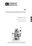
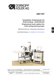
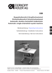
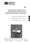
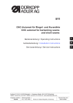
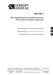
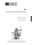
559 Doppelkettenstich Knopflochautomat Einfachkettenstich Schnürlochautomat Automatic double-chainstitch buttonholer Automatic single-chainstitch eyelet machine Bedienanleitung / Operating Instructions Aufstellanleitung / Installation Instructions 2 Serviceanleitung / Service Instructions 3 Postfach 17 03 51, D-33703 Bielefeld Potsdamer Straße 190, D-33719 Bielefeld Telefon +49 (0) 5 21/ 9 25-00 Telefax +49 (0) 5 21/ 9 25 24 35 www.duerkopp-adler.com Ausgabe / Edition: 07/2007 1 Änderungsindex Rev. index: 01.0 Printed in Federal Republic of Germany Teile-Nr./Part.-No.: 0791 559001 Anleitung, komplett / Manual, complete 559 Übersicht Summary Bedienanleitung Aufstellanleitung Serviceanleitung Operating Instructions Installation Instructions Service Instructions Bauschaltplan Interconnection-diagram 9890 580001 B 9890 580001 B Pneumatikgeräteplan Pneumatic circuit plan 9770 559001 9770 559001 Alle Rechte vorbehalten. Eigentum der Dürkopp Adler AG und urheberrechtlich geschützt. Jede, auch auszugsweise Wiederverwendung dieser Inhalte ist ohne vorheriges schriftliches Einverständnis der Dürkopp Adler AG verboten. All rights reserved. Property of Dürkopp Adler AG and copyrighted. Reproduction or publication of the content in any manner, even in extracts, without prior written permission of Dürkopp Adler AG, is prohibited. Copyright © Dürkopp Adler AG - 2007 Foreword This instruction manual is intended to help the user to become familiar with the machine and take advantage of its application possibilities in accordance with the recommendations. The instruction manual contains important information on how to operate the machine securely, properly and economically. Observation of the instructions eliminates danger, reduces costs for repair and down-times, and increases the reliability and life of the machine. The instruction manual is intended to complement existing national accident prevention and environment protection regulations. The instruction manual must always be available at the machine/sewing unit. The instruction manual must be read and applied by any person that is authorized to work on the machine/sewing unit. This means: – – – Operation, including equipping, troubleshooting during the work cycle, removing of fabric waste, Service (maintenance, inspection, repair) and/or Transport. The user also has to assure that only authorized personnel work on the machine. The user is obliged to check the machine at least once per shift for apparent damages and to immediatly report any changes (including the performance in service), which impair the safety. The user company must ensure that the machine is only operated in perfect working order. Never remove or disable any safety devices. If safety devices need to be removed for equipping, repairing or maintaining, the safety devices must be remounted directly after completion of the maintenance and repair work. Unauthorized modification of the machine rules out liability of the manufacturer for damage resulting from this. Observe all safety and danger recommendations on the machine/unit! The yellow-and-black striped surfaces designate permanend danger areas, eg danger of squashing, cutting, shearing or collision. Besides the recommendations in this instruction manual also observe the general safety and accident prevention regulations! General safety instructions The non-observance of the following safety instructions can cause bodily injuries or damages to the machine. 1. The machine must only be commissioned in full knowledge of the instruction book and operated by persons with appropriate training. 2. Before putting into service also read the safety rules and instructions of the motor supplier. 3. The machine must be used only for the purpose intended. Use of the machine without the safety devices is not permitted. Observe all the relevant safety regulations. 4. When gauge parts are exchanged (e.g. needle, presser foot, needle plate, feed dog and bobbin) when threading, when the workplace is left, and during service work, the machine must be disconnected from the mains by switching off the master switch or disconnecting the mains plug. 5. Daily servicing work must be carried out only by appropriately trained persons. 6. Repairs, conversion and special maintenance work must only be carried out by technicians or persons with appropriate training. 7. For service or repair work on pneumatic systems, disconnect the machine from the compressed air supply system (max. 7-10 bar). Before disconnecting, reduce the pressure of the maintenance unit. Exceptions to this are only adjustments and functions checks made by appropriately trained technicians. 8. Work on the electrical equipment must be carried out only by electricians or appropriately trained persons. 9. Work on parts and systems under electric current is not permitted, except as specified in regulations DIN VDE 0105. 10. Conversion or changes to the machine must be authorized by us and made only in adherence to all safety regulations. 11. For repairs, only replacement parts approved by us must be used. 12. Commissioning of the sewing head is prohibited until such time as the entire sewing unit is found to comply with EC directives. 13. The line cord should be equipped with a country-specific mains plug. This work must be carried out by appropriately trained technicians (see paragraph 8). It is absolutely necessary to respect the safety instructions marked by these signs. Danger of bodily injuries ! Please note also the general safety instructions. Index Page: Part 2: Installation Instructions cl. 559 1. Scope of delivery . . . . . . . . . . . . . . . . . . . . . . . . . . . . . . . . . . . . . . . . . . . . . . . . . 3 2. General notes and securing devices . . . . . . . . . . . . . . . . . . . . . . . . . . . . . . . . . . . . . 3 3. Table plate with dimensioning . . . . . . . . . . . . . . . . . . . . . . . . . . . . . . . . . . . . . . . . 4 4. Lifting eye bolt. . . . . . . . . . . . . . . . . . . . . . . . . . . . . . . . . . . . . . . . . . . . . . . . . . . 5 5. Assembly of the main switch . . . . . . . . . . . . . . . . . . . . . . . . . . . . . . . . . . . . . . . . . 5 6. Assembly of the control . . . . . . . . . . . . . . . . . . . . . . . . . . . . . . . . . . . . . . . . . . . . . 6 7. Potential equalization . . . . . . . . . . . . . . . . . . . . . . . . . . . . . . . . . . . . . . . . . . . . . . 7 8. Assembly of the waste container . . . . . . . . . . . . . . . . . . . . . . . . . . . . . . . . . . . . . . . 8 9. 9.1 9.2 9.3 9.4 9.5 9.6 Installation of the automatic buttonholer Adjusting the working height . . . . . . . . . . . . . . . . . . . . . . . . . . . . . . . . . . . . . . . . . . . 9 Attaching the thread stand . . . . . . . . . . . . . . . . . . . . . . . . . . . . . . . . . . . . . . . . . . . . 9 Connecting the pedal . . . . . . . . . . . . . . . . . . . . . . . . . . . . . . . . . . . . . . . . . . . . . . 10 Securing the stand . . . . . . . . . . . . . . . . . . . . . . . . . . . . . . . . . . . . . . . . . . . . . . . . 10 Connecting the maintenance unit . . . . . . . . . . . . . . . . . . . . . . . . . . . . . . . . . . . . . . . 11 Adjusting the operating pressure. . . . . . . . . . . . . . . . . . . . . . . . . . . . . . . . . . . . . . . . 11 10. 10.1 Lubrication Filling the oil reservoirs . . . . . . . . . . . . . . . . . . . . . . . . . . . . . . . . . . . . . . . . . . . . . 13 11. 11.1 11.2 11.3 11.4 Installing the sewing software General . . . . . . . . . . . . . . . . Loading the program . . . . . . . . Setting the sewing equipment . . Dongle-Update via the Internet . 12. Sewing test . . . . . . . . . . . . . . . . . . . . . . . . . . . . . . . . . . . . . . . . . . . . . . . . . . . . 16 . . . . . . . . . . . . . . . . . . . . . . . . . . . . . . . . . . . . . . . . . . . . . . . . . . . . . . . . . . . . . . . . . . . . . . . . . . . . . . . . . . . . . . . . . . . . . . . . . . . . . . . . . . . . . . . . . . . . . . . . . . . . . . . . . . . . . . . . . . . . . . . . . . . . . . . . . . . . 14 14 15 15 2 4 1 3 6 2 5 1. Scope of delivery The scope of delivery is dependent on your order. Please check before the assembly whether all required parts are available. – 1 Machine head – 2 Control – 3 Control panel – 4 Thread stand – 5 Maintenance unit – 6 Main switch – Right and left spacer for the distance between buttonhole and fabric edge – Tools and small parts in the accessories – Optional equipment (depending on the order) e.g.: - Stand - Pneumatic connection package - Integral sewing lamp - Foot switch 2. General notes and securing devices 2 ATTENTION ! The sewing automat must only be assembled by trained specialist staff. All work on the electric equipment of the automat must only be carried out by electricians or correspondingly instructed persons. The mains plug has to be pulled out. Securing devices Remove all securing devices before installing the sewing automat. – Remove tapes and battens from the machine head, the machine table and the stand. – Remove screw 1. This screw avoids that the machine head swivels up during transportation. – Remove screws 2. They will prevent the clamping plates from falling. 1 2 3 3. Table top with dimensioning If you manufacture the table top yourself, take the above sketch as an example for the dimensioning. The table top should be approx. 40 mm thick. Hole for the thread stand Positions for screwing on the brackets. To fasten the machine safely, use only the screwed inserts M8 x 25 DIN 7965 (the screwed inserts are not included in the accessories) with the screws for the brackets. 7 5 Positions for screwing on the protective bracket for the control Positions for screwing on the control The rubber-bonded metal buffers 5 have to be screwed between the brackets 7 and the machine pedestal, because otherwise vibrations are transmitted from the automat to the stand (all required parts are included in the accessories). 4 4. Lifting eye bolt The lifting eye bolt helps you to lift the automat into the stand. For example you can hoist the automat by a ceiling crane or you put a rigid bar (e.g. the bar of the thread stand) through the lifting eye bolt and lift the automat with 2 persons. The lifting eye bolt is included in the accessories. – Screw the lifting eye bolt 8 on the automat. – Lift the automat into the stand. – Unscrew the lifting eye bolt 8 when the automat is mounted. 5. 8 Assembly of the main switch 1 5 2 6 4 2 7 3 – – – – – – Loosen the screw 4 and remove the switching knob 5. Remove the main switch cover. For this purpose, unlock the tab in the hole 6. Insert the cable from the control box in the main switch. Connect the cable cores of the control box to the terminals L1 (1à brown) and L2 (2 à blue). Connect the protective earth (3 à yellow-green) of the control box to the main switch too. Make sure that the notch 7 of the main switch faces down. Put the main switch cover again. Put on the switching knob 5 and screw it tight. Hint If you manufacture the table top yourself, fit the main switch at an easily accessible place because the main switch is also the emergency stop switch. 5 6. Assembly of the control Attention! The control must not stand on the floor because otherwise the ventilation grid are covered. This can lead to the overheating of the control. 8 2 1 7 3 9 4 – – – – 6 8 10 5 Screw the control on the underside of the table top with the screws 2 and 3. The side carrying the data plate points to the front. Connect all plugs in field 1 and 4 with the respective bushes. The plugs are clearly marked with an imprint on cable 8 and the bushes at the casing 7! Cable and bush have the same designation. Check whether every plug is in the correct bush ! Screw plugs and bushes together. Finally screw 6 the protective bracket 5 under the table top so that the cables cannot be ripped out or damaged inadvertently. In addition secure the protective bracket by screwing it together with the control using the screws 10. X20 7 6 X30 X40 X50 7. Potential equalization 3 4 1 2 6 5 2 – – – Connect the potential compensation cable 1 to the stand using the screw and toothed washer 2 (included in the accessories). Screw on the potential compensation cable 1 from the stand together with the potential compensation cable 3 from the automat, on the control box through the screw 4. Screw on the potential compensation cable 5 from the sewing motor to the control box through screw 6. Attention ! When screwing on the potential compensation cable, make sure to lay the toothed washers on the stand or on the control box. 7 8. Assembly of the waste container 1 2 3 1 – – – 8 Screw the waste container under the pedestal of the automat as shown in the illustration. Connect the hose 3 with the waste container and the hose nozzle 2. The hose 3 sucks cutting waste into the container. Connect the waste container and the pressure supply with the compressed-air hose 1 (in the accessories). 9. Installation of the automatic buttonholer 1 2 3 9.1 Adjusting the working height The working height is infinitely variable between 73 cm and 90 cm (measured up to the upper edge of the table top). – Loosen the locking screws 1 and 2 on both sides of the stand. – Set the working table of the automatic buttonholer to the desired working height. – Tighten the locking screws 1 and 2. 9.2 2 Attaching the thread stand 6 6 – 4 – 3 – 5 Insert the thread reel stand 3 in the hole of the table top and fasten it with nuts and washers. Mount and align the thread reel bracket 5 and the unwinding arm 3 as shown in the illustration. Important: thread stand and unwinding arm must be positioned exactly one above the other. Depending on the type of thread reel the centering piece 6 must be set as shown in the above illustration. Incorrect settings can lead to sewing disturbances. 9 9.3 Connecting the pedal 1 2 – – – – – 9.4 Place the pedal 1 under the stand. Screw off the handwheel and the belt protection of the automat. Guide the cable of pedal 1 through the cable duct of the automat to the top. Connect the cable of pedal 1 with bush 2 (X406). Screw the belt protection and the handwheel on again. Securing the pedal 1 2 – – 10 Screw the two support plates down with nut 1 until the automat stands firmly and safely. Screw the counternut 2 upwards and tighten it. 9.5 Connecting the maintenance unit 1 4 2 3 The pneumatic system of the machine and its optional equipment must be supplied with compressed air containing absolutely no water or oil. – Screw the maintenance unit on the stand. – Connect the maintenance unit with the thicker one 3 of the three compressed-air hoses coming out of the cable chute of the automat. – Connect the thinner hose to the connection 4. – Connect the maintenance unit with your pressure supply. ATTENTION ! For a faultless function of the pneumatic control processes the compressed-air circuit must guarantee an operating pressure of 6 ± 0,5 bar. The compressed air must be clean (oil-free). Pneumatic connection package A pneumatic connection package for stands with maintenance unit and pneumatic optional equipment is available under order number 0797 003031: – Connection hose, 5 m long, Ø = 9 mm – Hose nozzles and hose clamps – Coupler socket and coupler plug R ¼" 9.6 Adjusting the operating pressure The operating pressure of the automatic buttonholer amounts to 6 bar. It can be read at the manometer 2. – For adjusting the operating pressure lift the twist handle 1 and twist it correspondingly. Turn in clockwise direction = increase the air pressure Turn counter-clockwise = reduce the air pressure 11 2 10. 4 Lubrication 5 1 1 3 1 1 1 2 1 2 Caution: Danger of injury ! Oil can cause skin eruption. Avoid a longer contact with the skin! Wash yourself thoroughly after a contact! ATTENTION ! The handling and disposal of mineral oils is subject to legal regulations. Deliver used oil to an authorized collecting station. Protect the environment. Be careful not to spill any oil! Fill up the oil reservoirs exclusively with lubricating oil DA-10 or an equivalent oil with the following specification: – Viscosity at 40°C: 10 mm² /s – Ignition point: 150°C 2 The oil can be bought at the sales points of DÜRKOPP ADLER AG under the following parts numbers: 250 ml Container: 9047 000011 1 l Container: 9047 000012 2 l Container: 9047 000013 5 l Container: 9047 000014 ATTENTION ! If the automatic buttonholer has not been used for a long time or after assembling the machine, oil the wicks, felts, looper and needle bar components. – – – – – – – 12 Loosen screws and remove the face and front plate Oil the felts and the wicks 1. Apply one or two drops of oil to the needle bar and needle bar bushing. Screw on the face and front plate. Remove the clamping plates. Oil the wick 3. Apply one or two drops of oil to the spreader 4 and the spreader plate 5. 10.1 Fill the oil reservoirs – Fill up the reservoirs 2 and 4 through the feed openings 1 and 3 up to the marking “max”. 1 2 3 4 2 13 11. Installing the sewing software 11.1 General Loading a specific sewing software in the DACIII control unit is possible with the help of the “Programmed Dongle”. The “Programmed Dongle” has a label indicating the class and software version. Such a loading (booting) may be used in order to provide several DACIII control unit with a sewing software (first installation) or to install a newer machine software (update). With the delivery of the machine only the test software (allowing the loading of sewing software) is installed in the control unit. The test software offers no further functions. If the test software gets damaged during the loading process, it is no longer possible to load a software using a dongle. In such a case use a PC with a loader cable. The detailed procedure for this is described at the homepage of Dürkopp Adler AG “www.duerkopp-adler.com” among the section of “Download Area” and “Software”. CAUTION ! Turn off the main switch before connecting the dongle. 11.2 Loading the program 1 – – – Insert the mains plug. Switch on the main switch. If the main menu does not appear on the display after a relatively long waiting time, the sewing software is missing. In this case, the sewing software must be loaded. – – Turn the machine off at the main switch. Insert the dongle 2 into the socket X110 (TEST-Interface) 1 of the control unit (see pictures). Switch on the main switch. The Software will be loaded. The loading process takes less than 60 seconds. During the loading process do not remove the dongle and do not switch off the machine. The machine proceeds with a warm start after the software is loaded. Remove the dongle 2. If necessary confirm the software version. Caution! The machine software must match the machine class. – – – – – 2 14 11.3 Setting the sewing equipment After the loading of the program, the control panel will display an error message “9010" (enter the sewing equipment). “OK” Key ïðñò Keys Press the “OK” key. Enter the code “2548” using the arrow keys. “OK” Key Press the “OK” key. The menu item 511 (sewing equipment) will be activated. “OK” Key ñò Keys Press the “OK” key. Select the equipment matching to the machine and subclass using the arrow keys and confirm it through the “OK” key. The main menu will then be displayed on the control panel. The machine is now ready for use. CAUTION ! A wrong setting of the sewing equipment can damage the sewing machine. 2 11.4 Dongle-Update via Internet Dongles can be updated with programs available from the Dürkopp Adler homepage. Please visit our Internet site “www.duerkopp-adler.com” where you will find the relevant programs in the “Download” area. Prerequisite is our auxiliary download software “Dongle Copy” which is available in the same section together with instructions for easy use. 15 12. Sewing test After finishing the assembly work a sewing test has to be made: – Insert the mains plug. Caution: Danger of injury ! Needle thread, looper thread and gimp thread must only be threaded in when the machine is switched off or in the threading in mode! – – – – – – – – – Insert needle Thread in looper thread (see operating instructions). Thread in needle thread (see operating instructions). If desired, thread in gimp thread (see operating instructions). Switch on main switch. Load workpiece to be processed. Select a buttonhole type and adjust a low speed at first (see operating instructions). Gradually increase the speed. Check that the buttonhole meets the desired requirements. If not: – Alter the thread tension (see operating instructions). Attention! If even after a longer waiting period the control panel still does not display the main menu, there is no program loaded on the control unit. In this case the program has to be loaded first. (See chapter “Installing the sewing software”). 16