1
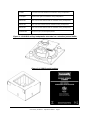
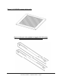
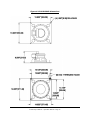
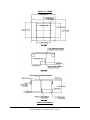
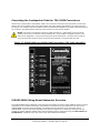
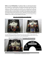
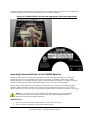
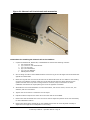
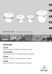
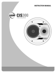
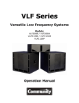
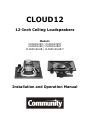
CLOUD12
12-Inch Ceiling Loudspeakers
Models:
CLOUD1299 / CLOUD1299T
CLOUD1266 / CLOUD1266T
CLOUD12SUB / CLOUD12SUB-T
Installation and Operation Manual
EC STATEMENT OF CONFORMITY
This document confirms that the range of products of Community Professional Loudspeakers bearing the CE
label meet all of the requirements in the EMC directive 89/336/EEC laid down by the Member States Council
for adjustment of legal requirements. Furthermore, the products comply with the rules and regulations
referring to the electromagnetic compatibility of devices from 30-August-1995.
The Community Professional Loudspeaker products bearing the CE label comply with the following
harmonized or national standards:
DIN EN 55013:08-1991
DIN EN 55020:05-1995
DIN EN 55082-1:03-1993
The authorized declaration and compatibility certification resides with the manufacturer and can be viewed
upon request. The responsible manufacturer is the company:
Community Light & Sound
333 East 5th Street
Chester, PA 19013
USA
TEL: 1-610 876-3400
FAX: 1-610 874-0190
Chester, PA USA May 2011
About this manual: Every effort has been made to ensure that the information contained in this manual
was complete and accurate at the time of printing. However, due to ongoing technical advances, changes or
modifications may have occurred that are not covered in this publication. The latest version of this manual
and the most recent product information published by Community is always available at
http://www.communitypro.com.
Community CLOUD12 – Operation Manual - Page 2
TABLE OF CONTENTS
IMPORTANT SAFETY INFORMATION .......................................................................................... 4
UNPACKING AND INSPECTION ................................................................................................. 5
CLOUD12 OVERVIEW.............................................................................................................. 6
Table 1: CLOUD12 models and accessories ............................................................................ 6
CLOUD12 ASSEMBLY .............................................................................................................14
WIRING AND INSTALLATION ..................................................................................................15
Installing Backbox Fittings for Conduit and Strain Relief ..........................................................15
Connecting Strain Relief to Cable and Loudspeaker Assembly ..................................................16
Connecting the Loudspeaker Cable for 8 Ohm (Low Impedance) Connections .............................17
Connecting the Loudspeaker Cable for 70V/100V Connections .................................................18
CLOUD12SUB Ceiling Mount Subwoofer Overview ..................................................................18
Attaching Channel Rail Kits to the C12BB3 Backbox................................................................20
Suspending the C12BB3 Backbox ........................................................................................22
Attaching the CLOUD12 Loudspeaker to the C12BB3 Backbox ..................................................24
Attaching the C12SQGRL Grille to the CLOUD12/C12BB3 Assembly ..........................................26
WARRANTY INFORMATION AND SERVICE .................................................................................27
TABLE OF FIGURES
Figure 1: CLOUD12 ceiling loudspeaker mounted on a standard ported baffle .................................................... 7
Figure 2: C12BB3 metal backbox ................................................................................................................. 7
Figure 3: C12SQGRL square white grille ........................................................................................................ 8
Figure 4: Channel rails available in lengths of 23.75 inches, ............................................................................ 8
Figure 5: CLOUD12 dimensions .................................................................................................................... 9
Figure 6: CLOUD12SUB dimensions ............................................................................................................ 10
Figure 7: C12BB3 backbox dimensions ........................................................................................................ 11
Figure 8: C12SQGRL grille dimensions ........................................................................................................ 12
Figure 9: RAIL24-PR channel rail dimensions ............................................................................................... 12
Figure 10: RAIL30-PR channel rail dimensions ............................................................................................. 13
Figure 11: RAIL48-PR channel rail dimensions ............................................................................................. 13
Figure 12: CLOUD12 assembly with backbox, grille and channel rails .............................................................. 14
Figure 13: Knocking out the knockout with a hammer and punch ................................................................... 15
Figure 14: Connecting strain relief .............................................................................................................. 16
Figure 16: Attaching the loudspeaker cable to the CLOUD12 input panel ......................................................... 17
Figure 17: CLOUD1266T and CLOUD1299T input panel (70V/100V operation).................................................. 18
Figure 18: CLOUD12SUB and CLOUD12SUB-T .............................................................................................. 19
Figure 19: CLOUD12SUB wiring and input panel (8 ohm operation) ................................................................ 19
Figure 20: CLOUD12SUB-T wiring and input panel (70V/100V operation) ........................................................ 20
Figure 21: Channel rail kit with tools and accessories ................................................................................... 21
Figure 22: Tightening the rail kit to the backbox .......................................................................................... 22
Figure 23: “Snugging” the ¼-inch eyebolts .................................................................................................. 23
Figure 24: Eyebolt load ratings .................................................................................................................. 23
Figure 25: Proper handling of the CLOUD12 loudspeaker ............................................................................... 24
Figure 26: Aligning the CLOUD12 with the backbox ...................................................................................... 25
Figure 27: CLOUD12 installed / gasket compressed ...................................................................................... 25
Figure 28: C12SQGRL grille in place on the CLOUD12 assembly ..................................................................... 26
Community CLOUD12 – Operation Manual - Page 3
IMPORTANT SAFETY INSTRUCTIONS
Always follow these basic safety precautions when using or installing CLOUD12 loudspeakers and
accessories:
Read these instructions.
Keep these instructions.
Heed all warnings.
Follow all instructions, particularly those pertaining to rigging, mounting, hanging and electrical
connections.
Do not use this apparatus near water.
Clean only with dry cloth
Do not block any ventilation openings. Install in accordance with the manufacturer’s instruction.
Do not install near any heat sources such as radiators, heat registers, stoves, or other apparatus
(including amplifiers) that produce heat.
Only use attachments/accessories that are specified and approved by the manufacturer.
Unplug this apparatus during lightning storms or when unused for long periods of time.
Refer all servicing to qualified service personnel. Servicing is required when the apparatus has been
damaged in any way, such as power-supply cord or plug is damaged, liquid has been spilled or
objects have fallen into the apparatus, the apparatus has been exposed to rain or moisture, does
not operate normally, or has been dropped.
Do not expose this equipment to dripping or splashing liquids.
The terms caution, warning, and danger may be used in this manual to alert the reader to important safety
considerations. If you have any questions or do not understand the meaning of these terms, do not proceed
with installation. Contact your local dealer, distributor, or call Community directly for assistance. These
terms are defined below:
CAUTION: describes an operating condition or user action that may expose the equipment or user
to potential damage or danger.
WARNING: describes an operating condition or user action that will likely cause damage to the
equipment or injury to the user or to others in the vicinity.
DANGER: describes an operating condition or user action that will immediately damage the
equipment and/or be extremely dangerous or life threatening to the user or to others in the vicinity.
WARNING:
To reduce the risk of fire or electric shock, do not expose this apparatus to rain or moisture.
These servicing instructions are for use by qualified service personnel only. To reduce the risks of
fire or electric shock do not perform any servicing other than that contained in the operating
instructions unless you are qualified to do so.
The loudspeakers described in this manual are designed to be ‘flown’ or suspended for maximum acoustical
performance using a variety of rigging hardware, means, and methods in some applications. It is essential
that all installation work involving the suspension of these loudspeaker products be performed by
competent, knowledgeable persons who understand safe rigging practices. Severe injury and/or loss of life
may occur if these products are improperly installed. Please read the section on wiring and installation for
additional information.
__
____________________________________________
PRECAUTION: Veuillez toujours suivrent ces mesures de sécurité de base lors de l'utilisation ou lors
de l'installation des haut-parleurs CLOUD12 et de ces accessoires:
Lisez et Gardez les instructions.
Observez tous les avertissements.
Suivez toutes les instructions, particulierement ceux concernant le calage, support, montage et
raccordements électriques.
Ne pas utiliser cet appareil près de l'eau.
Nettoyez seulement avec un tissu sec.
Ne pas bloquer les ouvertures de ventilation. Installer conformément aux instructions du
fabricant.
Ne pas installer près des sources de chaleur comme les radiateurs, les cuisinières, foyers ou
autres appareils (y compris les amplificateurs) qui peuvent produire de la chaleur.
Community CLOUD12 – Operation Manual - Page 4
Utilisez seulement les accessoires qui sont spécifiés et approuvés par le fabricant.
Débranchez cet appareil pendant les orages de foudre ou si inutilisé pendant de longues
périodes.
Référez tout entretient au personnel qualifié de service. Ceci est exigé quand l'appareil a été
endommagé de quelque façon, incluant le fil d'alimentation et ou l'embout du fil a été
endommagé, des liquides ont été renversés ou des objets sont tombé à l'intérieur de l'appareil,
l'appareil a été exposé à la pluie ou l'humidité, l'appareil ne fonctionne pas normalement ou a
été échappé.
N'exposez pas cet équipement à l'égoutture ou des liquides d'éclaboussement.
Les termes attention, avertissement, et danger peut être utilises dans ce manuel pour alerter le lecteur aux
considérations importantes de sûreté. Si vous avez des questions ou ne comprenez pas la signification de
ces termes, ne procédez pas à l'installation. Contactez votre detaillant, distributeur, ou Community
directement pour assistance. Les termes sont définies ci-dessous:
ATTENTION: décrit une condition de fonctionnement ou une action d'utilisateur qui peuvent
exposer l'équipement ou l'utilisateur aux dommages potentiels ou au danger.
AVERTISSEMENT: décrit une condition de fonctionnement ou une action d'utilisateur qui peuvent
causer des dommages probable à l'équipement et/ou à l'utilisateur et à ceux se trouvant à
proximité.
DANGER: décrit une condition de fonctionnement ou une action d'utilisateur qui endommageront
immédiatement l'équipement et/ou seront extrêmement dangereuses et qui peut représenter un
danger pour la vie à l'utilisateur et à ceux se trouvant à proximité.
______________________________________________________________________________________
AVERTISSEMENT:
Pour réduire le risque de feu ou de décharge électrique, ne pas exposer cet appareil à la pluie ou
l'humidité.
Ces instructions d'entretient sont pour l'usage d'un personnel de service qualifié seulement. Pour
réduire le risque de feu ou de décharge électrique n'exécutez aucun entretient autrement que ce qui
est contenu dans les instructions d'opérations à moins que vous êtes qualifié pour le faire.
______________________________________________________________________________________
Les haut-parleurs décrits en ce manuel sont conçus pour être accroché ou suspendus afin d'atteindre une
exécution acoustique maximum en utilisant une série de differents matériaux, moyens, et méthodes de
calage dans certaines applications. Il est essentiel que tout le travail d'installation impliquant la suspension
de ces produits de haut-parleur soit effectué de facon securitaire par des personnes compétentes et
bien formées dans les methodes de calage. Des blessures graves et/ou des pertes humaines peuvent se
produire si ces produits sont incorrectement installés. Veuillez lire la section sur le câblage et l'installation
pour des informations supplémentaires.
______________________________________________________________________________________
UNPACKING AND INSPECTION
CLOUD12 loudspeakers are inherently rugged and are carefully packed in sturdy cartons. However, it is
wise to thoroughly inspect each unit after it has been removed from the packaging, as damage could occur
during shipping.
Please note that once the shipment has left your dealer or the Community factory, the responsibility for
damage is always borne by the freight company. If damage has occurred during shipping, you must file a
claim directly with the freight company. It’s very important to contact the freight company as soon as
possible after receiving your shipment, as most freight companies have a short time limit within which they
will investigate claims. Make sure to save the carton and the packing material, as most claims will be
denied if these materials are not retained. Your Community dealer and the factory will try to help in any
way they can, but it is the responsibility of the party receiving the shipment to file the damage claim.
It’s always a good idea to retain the carton and packing materials indefinitely, if possible, in the event that
the unit may need to be returned to your dealer or distributor for repair in the future.
Each shipping carton contains the following items:
CLOUD12 ceiling loudspeaker mounted on a standard ported baffle (Qty 1)
Four 8/32 screws (for mounting the baffle to a C12BB3 backbox sold separately)
Operation manual (Qty 1)
Warranty card (Qty 1)
Community CLOUD12 – Operation Manual - Page 5
CLOUD12 OVERVIEW
Thank you for purchasing your new Community CLOUD12 Series High Output Ceiling Loudspeakers. The
CLOUD12 and CLOUD12SUB ceiling loudspeakers are extremely high output devices, intended to meet the
needs of the professional sound contractor for a variety of professional sound installation applications.
Available in either 60 x 60 degree or 90 x 90 degree coverage patterns, and in both 8 ohm and 70V/100V
formats, the 12-inch woofer and high output co-axially mounted 1-inch tweeter deliver high quality sound
over a wide coverage area. For installations that require extra bass output, the CLOUD12SUB provides a
matched 12-inch ceiling-mount subwoofer.
The CLOUD12 and CLOUD12SUB are provided with multi-terminal barrier strips for amplifier connection. The
70V/100V versions of the CLOUD12 and CLOUD12SUB are provided with the following 70V wattage taps:
25/50/100/200W. For applications outside North America, the following 100V taps are offered:
50/100/200W.
The CLOUD12 and CLOUD12SUB loudspeakers employ Community's advanced technology DYNA-TECHTM
driver protection system. Functioning as a multi-stage limiter, DYNA-TECH circuitry provides precise and
repeatable protection by reducing excessive power to the drivers under abusive conditions. There are
numerous advantages to this type of multi-stage protection circuitry. The trip point is pre-set to engage at
exactly the same time on all loudspeakers that are powered from the same amplifier. The initial stages of
DYNA-TECH protection circuitry do not rely on, and are not affected by heat build-up. If the system is
operated in the second-stage mode of protection for a long period of time, or if the input level is increased
to try to overcome the volume drop from the second-stage protection circuitry, a solid-state circuit breaker
will trip and remove all signal from the loudspeaker until the input level is reduced. Because this circuit
breaker is heat sensitive, it provides a final level of protection that takes heat into account as well as power.
The CLOUD12 and CLOUD12SUB come mounted on a standard ported baffle, and are equipped with eight
(8) mounting points for industry standard backboxes. Each package includes four (4) 8/32 screws for
mounting the baffle to a backbox.
The CLOUD12 and CLOUD12SUB can be flush-mounted into any ceiling type, or alternatively can be
suspended in an open ceiling. For proper installation, the CLOUD12 assembly must be mounted to a
backbox, such as the Community C12BB3 heavily braced 3.0-cubic foot metal backbox. Additional
accessories available for the CLOUD12 include the C12SQGRL square white grille, and installation channel
rails in 23.75-inch, 30-inch and 47.75-inch lengths (RAIL24-PR, RAIL30-PR and RAIL48-PR, respectively).
Table 1 lists a summary of the available CLOUD12 models and accessories.
Table 1: CLOUD12 models and accessories
Part Number
Description
CLOUD1266
Two-way, full-range 12-inch coaxial ceiling loudspeaker with 60° x
60° coverage, 8 ohm operation
CLOUD1266T
Two-way, full-range 12-inch coaxial ceiling loudspeaker with 60° x
60° coverage, 70V/100V operation
CLOUD1299
Two-way, full-range 12-inch coaxial ceiling loudspeaker with 90° x
90° coverage, 8 ohm operation
CLOUD1299T
Two-way, full-range 12-inch coaxial ceiling loudspeaker with 60° x
60° coverage, 70V/100V operation
CLOUD12SUB
12-inch ceiling mount subwoofer, 360° x 180° coverage, 8 ohm
operation
CLOUD12SUB-T
12-inch ceiling mount subwoofer, 360° x 180° coverage, 70V/100V
operation
Community CLOUD12 – Operation Manual - Page 6
C12BB3
3.0 cubic foot metal backbox for CLOUD12 ceiling loudspeakers
C12SQGRL
Square white grille for CLOUD12 ceiling loudspeakers
RAIL24-PR
Pair of 23.75-inch channel rails for CLOUD12 ceiling loudspeakers
RAIL30-PR
Pair of 30-inch channel rails for CLOUD12 ceiling loudspeakers
RAIL48-PR
Pair of 47.75-inch channel rails for CLOUD12 ceiling loudspeakers
1/4EYBLTKIT
Kit of four (4) 1/4"-20 forged eyebolts
Figure 1: CLOUD12 ceiling loudspeaker mounted on a standard ported baffle
Figure 2: C12BB3 metal backbox
Community CLOUD12 – Operation Manual - Page 7
Figure 3: C12SQGRL square white grille
Figure 4: Channel rails available in lengths of 23.75 inches,
30 inches and 47.75 inches (sold in pairs)
Community CLOUD12 – Operation Manual - Page 8
Figure 5: CLOUD12 dimensions
Community CLOUD12 – Operation Manual - Page 9
Figure 6: CLOUD12SUB dimensions
Community CLOUD12 – Operation Manual - Page 10
Figure 7: C12BB3
backbox dimensions
Community CLOUD12 – Operation Manual - Page 11
Figure 8: C12SQGRL grille dimensions
Figure 9: RAIL24-PR channel rail dimensions
Community CLOUD12 – Operation Manual - Page 12
Figure 10: RAIL30-PR channel rail dimensions
Figure 11: RAIL48-PR channel rail dimensions
Community CLOUD12 – Operation Manual - Page 13
CLOUD12 ASSEMBLY
The assembly diagram below illustrates how the CLOUD12 loudspeaker, C12BB3 backbox, C12SQGRL grille
and channel rails are assembled together. Please note that the C12BB3 ships as a backbox only, and all
other parts shown are optional accessories.
Figure 12: CLOUD12 assembly with backbox, grille and channel rails
Community CLOUD12 – Operation Manual - Page 14
WIRING AND INSTALLATION
This manual will serve to assist in wiring and physically mounting CLOUD1266, CLOUD1266T, CLOUD1299,
CLOUD1299T, CLOUD12SUB and CLOUD12SUB-T loudspeakers. The directions include assistance to those
installers using a complete Community package of loudspeakers and accessories, including the C12BB3
backbox, C12SQGRL square grille and appropriate tile rails. If accessory products from a different
manufacturer are used, please refer to the installation manuals supplied with those products.
For protection against electrical shock and to meet the requirements of the UL2043
standard, the speaker assembly must be installed in a Listed Community Model C12BB3
Back Box or similar UL1480/UL2043 listed enclosure. Minimum dimensions for the
enclosure must be 23” wide x 20” deep by 12” tall with a minimum wall thickness of
1.2mm.
Installing Backbox Fittings for Conduit and Strain Relief
Required tools:
One hammer and knockout punch tool
One step-bit for adjusting knockout diameter (optional)
Safety glasses, gloves and other personal safety gear are recommended as this process involves
striking metal parts and chipping away debris around the knockouts.
NOTE: All electrical installation connections for speaker lines are subject to local, state, and federal
building & fire codes. The selection of appropriate electrical hardware to interface with the C12BB3
lies solely with the installation professional. Community recommends that an appropriately licensed
engineer, electrician, or other professional identify and select the appropriate conduit, fittings, wire,
etc. for the installation.
Instructions for installing backbox fittings for conduit and strain relief:
1.
The C12BB3 comes equipped with knockout fittings on each side panel measuring:
a. 21/32” (17mm) to accommodate 3/4” fittings
b. 15/16” (24mm) to accommodate 1” fittings
2.
The knockouts are removed with a hammer and punch using the same techniques for removing
knockouts in other types of electrical boxes. A step-bit can be used to modify the diameter of the
knockout to accommodate larger conduit sizes.
3.
Insert appropriate fittings and tighten sufficiently for wire path concealment and strain relief, in
accordance with applicable codes.
4.
The acoustical damping batting material on the interior of the C12BB3 backbox should not cover the
inside surface of knockouts. If the batting covers the knockouts, peel back about four inches to
expose the knockouts. Trim off any excess batting that has been peeled back so that it will not
interfere with the loudspeaker’s function.
White mastic acoustical material on the C12BB3 (looks like white plaster) can be chipped away as needed to
allow electrical fittings to seat securely on the metal surface surrounding the knockout.
Figure 13: Knocking out the knockout with a hammer and punch
Community CLOUD12 – Operation Manual - Page 15
Connecting Strain Relief to Cable and Loudspeaker Assembly
Pass the loudspeaker cable through the appropriate knockout opening in the backbox and secure the cable
with a standard electrical tie-wrap (not provided) to provide strain relief (see figures below).
Figure 14: Connecting strain relief
STRAIN RELIEF PREPARATION
TIGHTENING STRAIN RELIEF #1
TIGHTENING STRAIN RELIEF #2
PREPARING TO CUT TIE-WRAP
CUTTING TIE-WRAP
COMPLETED STRAIN RELIEF
Community CLOUD12 – Operation Manual - Page 16
Connecting the Loudspeaker Cable for 8 Ohm (Low Impedance)
Connections
Connect the common side of the speaker cable to the " - " terminal on the input block. Connect the positive
side of the speaker cable to the " + " terminal on the input block. 14 AWG twisted pair speaker cable is
recommended for most 8 ohm applications when using spade or ring terminals. The speaker input block will
accept up to 10 AWG cable directly without spade terminals. For multiple speakers, attach the subsequent
speakers by parallel connecting them to the " - " and " + " input terminals of the previous speaker.
NOTE: Community recommends crimping a spade terminal (1/4” width spade) to the end of the
speaker wire prior to connection to the terminal block. In the absence of spade terminals, wire
ends can be stripped ¼” (7mm) and connected to the terminal block. Be careful not to strip too
much as frayed wire ends can short across the terminal block. Ring terminals do not fit.
Figure 15: CLOUD1266 and CLOUD1299 input panel (8 ohm operation)
Figure 16: Attaching the loudspeaker cable to the CLOUD12 input panel
Community CLOUD12 – Operation Manual - Page 17
Connecting the Loudspeaker Cable for 70V/100V Connections
Connect the common side of the speaker cable to the “common” terminal on the input block. Connect the
positive side of the speaker cable to the appropriate 70V/100V wattage tap based on the requirements of
the project. For multiple 70V/100V speakers, attach the subsequent speakers by parallel connecting them to
the “common” and appropriate autoformer input terminals of the previous speaker.
NOTE: Community recommends crimping a spade terminal (¼" width spade) to the end of the
speaker wire prior to connection to the terminal block. In the absence of spade terminals, wire
ends can be stripped ¼" (7mm) and connected to the terminal block. Be careful not to strip too
much as frayed wire ends can short across the terminal block. Ring terminals do not fit.
Figure 17: CLOUD1266T and CLOUD1299T input panel (70V/100V operation)
CLOUD12SUB Ceiling Mount Subwoofer Overview
The CLOUD12SUB ceiling subwoofer is the same size and weight as the full-range CLOUD12 Series of ceiling
loudspeakers. All mechanical assembly and installation instructions and procedures are the same for the
CLOUD12SUB as the full-range assemblies. The autoformer tap selections on the 70V/100V version
CLOUD12SUB-T and the full-range assemblies are identical. Differences in sensitivity among the various
models will require different wattage taps, and all amplifier power is calculated using the total number of
loudspeakers, regardless of the mix of full-range and subwoofer assemblies.
Community CLOUD12 – Operation Manual - Page 18
NOTE: The electrical damping factor of the subwoofer amplifier is a critical factor when selecting
equipment to support the CLOUD12SUB. Damping factor refers to the power amplifier’s ability to
stop (or “dampen”) a reproduced frequency. The higher the damping factor, the better the amplifier
will control the LF driver. Bass frequencies are more difficult to control than higher frequencies, and
therefore the damping factor becomes more important to the overall system. The higher the
damping factor, the better the amplifier will control the LF driver. The damping factor of an amplifier
is dependent largely on its output impedance. A high damping factor indicates that an amplifier will
have greater control over the movement of the speaker cone, particularly near the resonant
frequency of the driver’s mechanical resonance. Community recommends that the damping factor of
the subwoofer amplifier be greater than 100 @ 8 ohms. Additionally, the cable chosen should be at
least 14 AWG for optimum LF reproduction with minimum line loss and minimum reduction in
damping factor. It should be further noted that damping factor is more of an influence in a low
impedance (8 ohm) system than a high impedance (70.7V) system.
Figure 18: CLOUD12SUB and CLOUD12SUB-T
CLOUD12SUB (8 OHM OPERATION)
CLOUD12SUB-T (70V/100V OPERATION)
The CLOUD12SUB ceiling subwoofer is shipped with 24 inches of two-conductor, 16 AWG speaker cable
attached via crimped spade terminals on one end. The other end is stripped and ready to connect via wire
nut to incoming cable. See the figure below for input terminal designation.
Figure 19: CLOUD12SUB wiring and input panel (8 ohm operation)
Community CLOUD12 – Operation Manual - Page 19
The CLOUD12SUB-T ceiling subwoofer is shipped with a 5-conductor cable for connection to the appropriate
autoformer input position. See the figures below for input terminal designation.
Figure 20: CLOUD12SUB-T wiring and input panel (70V/100V operation)
Attaching Channel Rail Kits to the C12BB3 Backbox
Community offers rail kits in three popular lengths: 24 inches, 30 inches and 48 inches. Choose the
appropriate size kit to fit the architectural structural supports for the CLOUD12 speaker and C12BB3
backbox assembly. The CLOUD12 speaker system is meant primarily for installation in ceilings, and these
instructions follow that path. Other installation locations, such as in walls, are also possible.
Rail kits can be installed directly to the building structure, and can be used to create additional rigging
solutions. Please remember that when using rail kits for rigging supported by steel wire, rope, chain, or
similar materials, the center of gravity of the assembly might be above the attachment points on the rail kit.
NOTE: The rail itself may not provide sufficient stiffness if rigged from a point located far
from the backbox tabs. Community recommends all mounting and rigging methods be
approved by a qualified Professional Engineer.
Required tools:
Two 7/16” (11mm) wrenches, socket drivers, or spin-tights (nut drivers).
Torque wrench (as needed) to verify proper fastener torque.
Community CLOUD12 – Operation Manual - Page 20
Figure 21: Channel rail kit with tools and accessories
Instructions for attaching the channel rails to the backbox:
1.
Unpack
a.
b.
c.
d.
e.
f.
the RAIL24-PR, RAIL30-PR, or RAIL48-PR kit and find the following contents:
Two mounting rails
(4) 1/4-20 x 1” Hex Head Screws
(4) 1/4” Hex Nuts
(8) 1/4” Flat Washers
(4) 1/4” Lock Washers
Liability Waiver Card
2.
Set rail along one side of the C12BB3 backbox so that the leg of the rail aligns with the slotted holes
against the slotted tabs.
3.
Orient the leg with the row of ten 9/32” holes in the desired direction for it to fasten to the building
structure. The installer will likely orient the rail so that this leg faces the same direction as the
speaker and will rest on top of the ceiling structure. However, keep in mind there are other
installation scenarios that require placing the rail in the opposite orientation.
4.
Assemble the hex screws hardware. For each tab location, use one hex screw, one hex nut, two
washers, and one lock washer.
5.
Tighten the hex screws to a maximum 10 lb-ft torque.
6.
Repeat the above steps for the other rail on the other side of the C12BB3.
7.
Please note that the slotted hole in the rail can be used to adjust the position of the rail horizontally
for best installation location.
8.
Please note also that the slotted tab on the C12BB3 permits the rail to be adjusted vertically to
adjust the trim height of the loudspeaker in the ceiling.
Community CLOUD12 – Operation Manual - Page 21
Figure 22: Tightening the rail kit to the backbox
Suspending the C12BB3 Backbox
The C12BB3 backbox will generally be installed in tile-based ceiling systems, but can also be installed in
open space. Use eyebolt kits (part number 1/4EYBLTKIT) to fasten conventional rigging hardware to the
C12BB3.
NOTE: There are several 1/4-20 suspension points located in the back panel of the
C12BB3. These can be used as alternate support and rigging points for open ceiling plan
installation. Community recommends all mounting and rigging methods be approved by a
qualified Professional Engineer.
Required Tool:
Stiff screwdriver (or similar tool) for snugging eyebolts
Instructions for suspending the backbox using eyebolts:
1.
Unpack the 1/4EYBLTKIT and find the following items:
a. (4) 1/4” Forged Shouldered Eyebolts
b. (4) Cup Washers
2.
Set aside (4) cup washers as they are not used for this application.
3.
Insert one eyebolt kit in each suspension point and turn it until seated snug on the rear of the
cabinet surface.
4.
Do not over-tighten the eyebolt. Once seated, the eyebolt will only need 1/8-turn to ¼-turn to
firmly tighten. Insert a stiff tool through the eye to help “snug” the eyebolt into position, but do not
use that as a tightening (or “torquing”) tool.
5.
In some cases shims (not included) will be necessary to adjust the orientation of the eyebolt so that
the plane of the eye correctly aligns with the direction of the attached suspension cable.
6.
The eyebolts should be installed tight enough to prevent accidental unfastening, but not tight
enough to damage the insert threads.
Community CLOUD12 – Operation Manual - Page 22
Figure 23: “Snugging” the ¼-inch eyebolts
Eyebolt Suspension:
The eyebolts must be screwed in so that the shoulder firmly contacts the surface of the enclosure. In all
cases the direction of pull on the eyebolt and mounting point should not exceed a maximum of 45º from the
vertical axis of the mounting point hole. Multiple cables that can independently support the loudspeaker
must also be used. See the following figure.
Figure 24: Eyebolt load ratings
NOTES:
There is no benefit in tightening the eyebolt more than hand tight. Never pull an eyebolt sideways
or at 90° to a vertical pull angle.
The CLOUD12 family of loudspeaker assemblies must be installed in a backbox prior to permanent
installation. In order to conform to local electrical codes, do not install any CLOUD12 loudspeaker
assembly in a ceiling without an appropriate backbox such as the Community C12BB3.
The CLOUD12 loudspeakers can generate substantial vibrations, which can cause the ceiling tile or
other parts of the support structure to audibly buzz. Depending on the nature of the ceiling tile and
the overall structure, the installer may elect to adhere dampening material (not provided) such as
neoprene under the tile rails or the edges of the tiles themselves to eliminate buzzing or rattling.
Community CLOUD12 – Operation Manual - Page 23
Attaching the CLOUD12 Loudspeaker to the C12BB3 Backbox
NOTE: The CLOUD12 loudspeaker weighs approximately 20 lbs and the C12BB3 backbox
weighs at least 40 lbs. Both are awkward and difficult to handle. Lift the CLOUD12 by the
speaker basket or main support backing only; do not use the terminal strip or the autoformer
(70V/100V versions only) as a lift point. It is highly recommended that two people work as a
team to install the C12BB3 backbox into the ceiling and the CLOUD12 assembly into the
backbox. Beware of sharp edges on the cast woofer basket. These are a normal remnant
of the casting process.
Required tools:
One #2 Philips Screwdriver
Safety glasses and other related personal safety gear are always recommended when working
overhead.
It is highly recommended that two people participate in this portion of the installation. Placing and
installing loudspeaker assemblies in a ceiling is a dangerous enterprise for one person to undertake.
Instructions for attaching the CLOUD12 to the backbox:
1.
Refer to instructions in this manual related to suspending the C12BB3 and supporting the C12BB3
safely.
2.
Make all necessary conduit or other wire path ingress installations before proceeding with the
installation. For more information on interfacing common conduit fittings with the C12BB3, please
refer to the portion of this manual addressing that topic.
3.
After removal of the CLOUD12 loudspeaker from the shipping container, find the following items:
Parts List for fastening CLOUD12 Loudspeaker to C12BB3 backbox:
(1) CLOUD12 Ceiling Loudspeaker
(1)
(4) 10-24 x 1/2" Philips Truss Head Screws
(1)
(4) #10 Flat Washers
(1)
(4) #10 Lock Washers
(1)
(4) 8/32 Screws
(1)
Warranty Documentation
Warranty Registration Card
Waiver of Liability Card
Installation and Operation Manual
Specification Sheet
Figure 25: Proper handling of the CLOUD12 loudspeaker
4.
Refer to instructions earlier in this manual to make the necessary electrical connections to the
loudspeaker’s amplifier circuit, being careful to observe polarity and to use the correct taps for
transformer-equipped (70V/100V) units.
Community CLOUD12 – Operation Manual - Page 24
5.
Set the CLOUD12 into the square hole in the C12BB3. Handle the speaker assembly by its metal
frame or baffle plate. Be careful to not handle the weight of the assembly by the electronic parts or
the speaker’s paper cone. It will likely require the assistance of a second worker to hold the
CLOUD12 speaker assembly. Alternately, a fixture might be devised to safely support the speaker
frame while fastening it into the C12BB3.
6.
Be sure that the neoprene rubber gasket material surrounding the outer edge of the speaker frame
makes contact and seals all the way along the perimeter of the raised square flange on the C12BB3.
7.
Insert and start threading all four 10-24 x ½" Philips Truss Head Screws using one #10 Flat Washer
and one #10 Lock Washer as shown in Figure 12. After all four screws have been threaded one or
two turns; tighten screws hand-tight so that the neoprene gasket is evenly compressed. Do not
over-tighten the Philips head screws, but do take care to ensure that they are firmly seated and that
the lock washer has compressed.
8.
Check and review that all steps above have been carefully followed.
Figure 26: Aligning the CLOUD12 with the backbox
Figure 27: CLOUD12 installed / gasket compressed
Community CLOUD12 – Operation Manual - Page 25
Attaching the C12SQGRL Grille to the CLOUD12/C12BB3 Assembly
Required tools:
One #2 Philips Screwdriver
Superlative vision and a flashlight to see the tiny black holes behind the grille when inserting the
screws
Safety glasses are highly recommended
Instructions for attaching the grille to the loudspeaker and backbox assembly:
1.
Unpack C12SQGRL and inspect contents to find the following:
(1) C12SQGRL white grille
(4) 8-32 x 1-1/2” Philips truss head screws
2.
The C12SQGRL is provided in white. The grille can be painted if another color is desired. Use a high
quality spray paint only. Prior to painting, the surface should be treated to remove the sheen from the
polyester powder coating. This can be done with fine grit sanding or chemical sheen removers such as
trisodium phosphate. Primer and finish coat paint is applied in the same manner as other metal
surfaces. If the C12SQGRL grille is roller or brush painted, the mesh material may become clogged with
paint, resulting in attenuating of high frequencies and subsequent poor sound.
3.
Please note the two locations at each corner of the CLOUD12 loudspeaker baffle plate for
attaching grilles. The holes closer to the perimeter of the baffle plate are used for the
C12SQGRL. The holes closer to the speaker cone are used for other manufacturer’s
compatible grilles.
4.
Place the C12SQGRL grille over the face of the CLOUD12 loudspeaker so that the edges of the grille
wrap around and conceal the edges of the baffle plate and surrounding ceiling material.
5.
Line up one of the 8-32 x 1-1/2” Philips truss head screws through one hole in the C12SQGRL and insert
it into the correct hole in the CLOUD12 baffle plate. Turn the screw one or two turns to get it started.
Repeat this process for the remaining three screws.
6.
Carefully snug all four mounting screws evenly so that both edges of the grille make firm contact with
surrounding ceiling material or so that the upper surface of the grille makes firm contact with the baffle
plate (for installations where the CLOUD12 speaker and backbox are installed in free space).
7.
Be sure the grille is tightened enough to be securely fastened to the CLOUD12 loudspeaker, and snug
enough to the ceiling material (or the baffle) so that the grille does not vibrate.
Figure 28: C12SQGRL grille in place on the CLOUD12 assembly
Community CLOUD12 – Operation Manual - Page 26
WARRANTY INFORMATION AND SERVICE
Transferable Warranty "(Limited)” Valid in the USA Only
Community CLOUD12 ceiling loudspeakers are warranted in the USA to be free from manufacturing defects
in materials and workmanship for a period of five years, as determined by one of the following two methods,
whichever is longer:
Starting from the date of retail purchase, as noted on the sales receipt from an authorized Community
dealer,
OR
Starting from the date of manufacture, determined by the serial number, if the sales receipt is not available.
This warranty applies to the product; therefore, the remainder of the warranty period will be automatically
transferred to any subsequent owner.
This warranty applies only to failure of a Community loudspeaker caused by defects in materials and
workmanship during the stated warranty period. It does not apply to a unit that has been subjected to
abuse, accident, modification, improper handling/installation, or repairs made without factory authorization
or by anyone other than authorized Community Field Service Stations. This warranty is void if the serial
number has been defaced, altered or removed.
Products covered by this warranty will be repaired or replaced at the option of Community, without charge
for materials or labor, provided all the terms of this warranty have been met.
Obtaining Warranty Service
Warranty service may be obtained from the factory, or from an authorized Field Service Station.
To obtain factory or field warranty service for products purchased in the United States, return the product
for inspection to the address below, freight prepaid, in the original packaging. If the original packaging is
not available, call or write Community Warranty Service to obtain proper packaging materials or hand carry
the product to the nearest Field Service Station.
Factory Service Center:
Community Warranty Service
333 East Fifth Street
Chester, PA 19013-4511 USA
Field Service Station:
Call (610) 876-3400 for the nearest Authorized Field Service Station
For factory service, please call (610) 876-3400 for a Return Authorization (R/A) number before shipping.
The following information must be included in the package:
1)
Owner’s complete name, daytime phone number, return street address and return authorization
number.
2)
The serial number of the product being returned and a copy of the retail sales receipt, if possible.
3)
A complete description of the problem(s) experienced, including a brief description of how the
equipment is being used and with what brand, model and output power of amplifier.
Upon receipt, the service center will determine if the problem is covered under warranty. If covered under
this warranty, the product will be repaired or replaced, at Community’s option, and returned to the owner
freight prepaid. If the problem is not covered under this warranty, the owner will be notified of the problem
with an estimate of the repair costs.
Community CLOUD12 – Operation Manual - Page 27
Consequential and Incidental Damages: Community shall not be liable for any consequential or incidental
damages including, without limitation, injury to persons, property, or loss of use. Some states do not allow
the exclusion or limitations of consequential or incidental damages, so the above limitations and exclusions
may not apply.
This Community warranty is not extended by the length of time which an owner is deprived of the use of the
product. Repairs and replacement parts provided under the terms of this warranty shall carry only the
remaining portion of the warranty.
Community reserves the right to change the design of any product from time to time, without notice and
with no obligation to make corresponding changes in products previously manufactured.
While this warranty gives specific legal rights, there may also be other rights that vary from state to state.
No action to enforce this warranty shall be permitted ninety days after expiration of the warranty period.
Warranty Information and Service for Countries Other Than the USA
To obtain specific warranty information and available service locations for countries other than the United
States of America, contact the authorized Community Distributor for your specific country or region.
Safety Agency Compliance
4001449
Conforms to UL1480 Standard
Conforms to UL2043 Standard
Certified to CSA C22.2 No. 60065 Standard
For protection against electrical shock and to meet the requirements of the UL2043
standard, the speaker assembly must be installed in a Listed Community Model C12BB3
Back Box or similar UL1480/UL2043 Listed enclosure. Minimum dimensions for the
enclosure must be 23” wide x 20” deep by 12” tall with a minimum wall thickness of
1.2mm.
Additional Compliance Information
Suitable for use in air handling spaces per NFPA70 National Electrical Code 2008 Article
300.22(c)(2) and NFPA 90 Installation of Air Conditioning and Ventilation Systems 2009
Article 4.3.11.2.6.5.
SUITABLE FOR USE IN AIR HANDLING SPACES
Community Professional Loudspeakers
333 East Fifth Street, Chester, PA 19013-4511 USA
Tel: 1-(610) 876-3400 | Fax: 1-(610)874-0190
www.communitypro.com
© 2011 All Rights Reserved
30JUNE2011