1
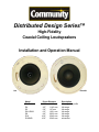
Distributed Design Series™
High-Fidelity
Coaxial Ceiling Loudspeakers
Installation and Operation Manual
D10
D10SUB
Model
D4LP
D4
D5
D6 & D6-B
D8
D10
D10SUB
Driver Diameter
4.5" 4.5"
5.0" 6.5"
8.0"
10.0"
10.0"
114.3 mm
114.3 mm
127 mm
165.1 mm
203.2 mm
254.0 mm
254.0 mm
Description
full-range, low profile
full-range
full-range
full-range
full-range
full-range
subwoofer
Introduction
Thank you for selecting the Community Distributed
Design Series™ of ceiling loudspeakers.
Whether you chose them because they deliver
exceptionally high quality sound, because they
have predictable, uniform coverage so spaces
are easy to lay out, because they are easy to
install and save time, or because they are very
competitively priced for such a high-performance,
durable loudspeaker, you can have confidence
you made the right choice.
The Distributed Design Series is built to satisfy
safety agency standards, with quality assured
by Community’s long history of building highperformance, durable loudspeakers for sound
reinforcement and contracting applications.
The Distributed Design Series is comprised of
these seven models:
Model
D4LP
D4
D5
D6 & D6-B
D8
D10
D10SUB
Driver Diameter
4.5" 114.3 mm
4.5" 114.3 mm
5.0" 127.0 mm
6.5" 165.1 mm
8.0" 203.2 mm
10.0" 254.0 mm
10.0" 254.0 mm
Response
full-range
full-range
full-range
full-range
full-range
full-range
subwoofer
Each model is available as a complete assembly,
including everything needed for standard
installations, or you can purchase packages for
the face portion only or the back can portion.
Each of these packages has components for two
loudspeakers. The D4LP Low Profile model fits
where deeper units cannot and may be retrofitted
into existing shallow cans.
Except for the D10SUB subwoofer, each of the
other six models is a true coaxial loudspeaker.
This means it has a real compression driver
concentrically arranged so that the upper
frequencies emerge through the center of the
low-frequency driver’s magnetic structure and
cone via a precisely tapered Tru-Phase™ highfrequency waveguide. This special construction
provides consistent, wide dispersion right up
to 16 kHz, all but eliminating high-frequency
narrowing. You don’t have the reflection and
diffraction problems at multiple frequencies found
with "straight tube" coaxial loudspeakers, simple
"whizzer-cone" loudspeakers, or front-mounted
soft dome high frequency loudspeakers (typically
Community Distributed Design Series
found in ceiling speakers at this price point) that
attempt to emulate a true coax design.
Further pattern improvement is achieved by
precisely mounting the low frequency driver
(and its’ concentric HF driver) dead-center in the
baffle, as contrasted to the offset designs used
by many others.
Most competitive ceiling loudspeakers typically
have a half-inch or greater, "step" in their face
where the grille is attached, and the low-frequency
driver is rear-mounted behind the grille plate.
Such designs produce unwanted reflections and
diffraction effects such as frequency response
peaks and nulls, polar irregularities, and phase
response problems. To avoid these issues,
Community Distributed Design baffles are very
close to the grille (less than 1/8 inch away).
The loudspeaker baffle and ceiling thus form
an uninterrupted planar surface for diffractionfree HF driver acoustic loading and a smooth,
predictable pattern. This makes it easy to lay
out your loudspeaker installation for optimum
coverage without those unwanted dead zones or
too-loud overlaps.
The Distributed Design Series saves you money
in several ways. (a) Their powerful magnetic
structures and efficient coils ensure high output,
which gives you more headroom per power
amplifier so you can use a smaller amp that will
save you money. (b) These loudspeakers are very
competitively priced and (c) Community designed
this series with place-through-the-cutout Tile
Support Bridge Rails, Drop-Stop™ installation
assistant tabs, Twist-Assist™ loudspeaker face
retainer tabs, and other innovations so that one
person on a ladder is easily able to install the
loudspeaker in the ceiling. Overall, this saves
a tremendous amount of time and labor during
the installation. You can use 8-ohm or constant
voltage distribution for which you get a 70 volt /
100 volt transformer built in.
We urge you to read these instructions carefully
and familiarize yourself with the features and
installation methods before you begin the job.
If you have any questions or concerns, please
contact Community right away.
Installation and Operation Manual Page 2
Table of Contents
Important Safety Instructions . . . . . . . . . . . . . . . . . . . . . . . . . . . . . 5
L’information de Sûreté Importante . . . . . . . . . . . . . . . . . . . . . . . . . . 6
Unpacking and Inspection . . . . . . . . . . . . . . . . . . . . . . . . . . . . . . . 7
Option 1: Full Ceiling Loudspeaker Assembly* . . . . . . . . . . . . . . . . . . . . 8
Option 2: Face Only. . . . . . . . . . . . . . . . . . . . . . . . . . . . . . . . . . . . . . . . 9
Option 3: Back Can . . . . . . . . . . . . . . . . . . . . . . . . . . . . . . . . . . . . . . . 10
Optional Accessories . . . . . . . . . . . . . . . . . . . . . . . . . . . . . . . . . . . . . . 11
Specifications . . . . . . . . . . . . . . . . . . . . . . . . . . . . . . . . . . . . . 12
Component Identification . . . . . . . . . . . . . . . . . . . . . . . . . . . . . . . 18
Wiring . . . . . . . . . . . . . . . . . . . . . . . . . . . . . . . . . . . . . . . . . . 20
Power Determination. . . . . . . . . . . . . . . . . . . . . . . . . . . . . . . . . . . . . . 20
Installation in back cans without conduit . . . . . . . . . . . . . . . . . . . . . . . 20
Installation of conduit to the back can . . . . . . . . . . . . . . . . . . . . . . . . . 22
Installing the Back Can in the Ceiling . . . . . . . . . . . . . . . . . . . . . . . . 23
General . . . . . . . . . . . . . . . . . . . . . . . . . . . . . . . . . . . . . . . . . . . . . . . 23
Procedure (for suspended ceiling). . . . . . . . . . . . . . . . . . . . . . . . . . . . 23
Dry-Wall Ceiling Installation.. . . . . . . . . . . . . . . . . . . . . . . . . . . . . . . . . 25
Details for Pre-Installation in a New Drywall Ceiling . . . . . . . . . . . . . . . . . 26
Inserting the Loudspeaker Assembly into the Back Can . . . . . . . . . . . . . . . 26
Painting the Loudspeaker . . . . . . . . . . . . . . . . . . . . . . . . . . . . . . . 27
Type of Paint. . . . . . . . . . . . . . . . . . . . . . . . . . . . . . . . . . . . . . . . . . . . . 27
Painting Process . . . . . . . . . . . . . . . . . . . . . . . . . . . . . . . . . . . . . . . . . 27
Secure the Loudspeaker Into the Back Can . . . . . . . . . . . . . . . . . . . . . 28
Loudspeaker Tap Setting . . . . . . . . . . . . . . . . . . . . . . . . . . . . . . . 30
Warranty Information and Service . . . . . . . . . . . . . . . . . . . . . . . . . . 31
Transferable Warranty "(Limited)" Valid in the USA Only . . . . . . . . . . . . . . . 31
Warranty Information and Service for Countries Other Than the USA . . . . . . . . 31
Shipping Damage. . . . . . . . . . . . . . . . . . . . . . . . . . . . . . . . . . . . . . . . . 31
Find the Latest Online . . . . . . . . . . . . . . . . . . . . . . . . . . . . . . . . . . . . . 31
About this manual
Every effort has been made to ensure that the information contained in this manual was complete and accurate at the
time of printing. However, due to ongoing technical advances, changes or modifications may have occurred that are
not covered in this publication. The latest version of this manual and the most recent product information published
by Community is always available at:
http://www.communitypro.com
Community Distributed Design Series
Installation and Operation Manual Page 3
Table of Figures
Figure 1. Full Ceiling Loudspeaker assembly package contents (typical) . . . . . . . . 8
Figure 2. Face Only package contents (typical) . . . . . . . . . . . . . . . . . . . . . 9
Figure 3. Back Can package contents (typical) . . . . . . . . . . . . . . . . . . . . . 10
Figure 4. Optional Accessories. . . . . . . . . . . . . . . . . . . . . . . . . . . . . . . . 11
Figure 5. D45-BC Back can dimensions. . . . . . . . . . . . . . . . . . . . . . . . . 14
Figure 6. D4-FO Loudspeaker dimensions. . . . . . . . . . . . . . . . . . . . . . . 14
Figure 7. D4LP-BC Back can dimensions. . . . . . . . . . . . . . . . . . . . . . . . 14
Figure 8. D5-FO Loudspeaker dimensions. . . . . . . . . . . . . . . . . . . . . . . 15
Figure 9. D6-BC Back can dimensions. . . . . . . . . . . . . . . . . . . . . . . . . . 15
Figure 10. D6-FO Loudspeaker dimensions . . . . . . . . . . . . . . . . . . . . . . 15
Figure 11. D8-BC Back can dimensions. . . . . . . . . . . . . . . . . . . . . . . . . 16
Figure 12. D8-FO Loudspeaker dimensions . . . . . . . . . . . . . . . . . . . . . . 16
Figure 13. D10-BC Back can dimensions. . . . . . . . . . . . . . . . . . . . . . . . 16
Figure 14. D10-FO Loudspeaker dimensions . . . . . . . . . . . . . . . . . . . . . . 16
Figure 15. D10SUB-FO Loudspeaker dimensions . . . . . . . . . . . . . . . . . . . 17
Figure 16. Face adapter ring detail. . . . . . . . . . . . . . . . . . . . . . . . . . . . . 17
Figure 17. Can adapter / trim ring detail. . . . . . . . . . . . . . . . . . . . . . . . . 17
Figure 18. Component part identification (1) . . . . . . . . . . . . . . . . . . . . . . 18
Figure 19. Component part identification (2) . . . . . . . . . . . . . . . . . . . . . . 19
Figure 20. Non-conduit guided wiring to can and wire restraint . . . . . . . . . . . . . 20
Figure 21. Internal wiring between can terminal block and loudspeaker . . . . . . . . 21
Figure 22. Conduit for protected wiring to can . . . . . . . . . . . . . . . . . . . . . 22
Figure 23. Redeploying the plug for wires entering from conduit . . . . . . . . . . . 22
Figure 24. Cutout template dimensions . . . . . . . . . . . . . . . . . . . . . . . . . 23
Figure 25. Installing a C-Ring support plate onto tile bridge support rails . . . . . . . 23
Figure 26. Drop-Stop™ tabs (highlighted) snap out over C-Ring support . . . . . . . 24
Figure 27. Turning the can clamp actuators clockwise securely locks the back can into
the ceiling.. . . . . . . . . . . . . . . . . . . . . . . . . . . . . . . . . . . . . . . 24
Figure 28. New installation in an existing drywall ceiling . . . . . . . . . . . . . . . . 25
Figure 29. New construction bracket for drywall or lath-and-plaster installations . . . . 26
Figure 30. Initial position (left) and loudspeaker face twisted to lock (right) . . . . . . 28
Figure 31. Four Twist-Assist™ face tabs inside the back can instantly secure the
loudspeaker to the back can with a twist. . . . . . . . . . . . . . . . . . . 28
Figure 32. Use the four included, captive, 4mm sheet metal screws to secure the
loudspeaker into the can. . . . . . . . . . . . . . . . . . . . . . . . . . . . 28
Figure 33. Grille safety clip and line (left) should look like this (right) when attached. . 29
Figure 34. Setting Loudspeaker Tap. . . . . . . . . . . . . . . . . . . . . . . . . . . . 30
Community Distributed Design Series
Installation and Operation Manual Page 4
Important Safety Instructions
Always follow these basic safety precautions
when using or installing Distributed Design
loudspeakers and accessories:
• Read these instructions.
• Keep these instructions.
• Heed all warnings.
• Follow all instructions, particularly those
pertaining to rigging, mounting, hanging and
electrical connections.
• Do not use this apparatus near water.
• Clean only with dry cloth.
• Do not block any ventilation openings. Install in
accordance with the manufacturer’s instruction.
• Do not install near any heat sources such
as radiators, heat registers, stoves, or other
apparatus (including amplifiers) that produce
heat.
• Only use attachments/accessories that are
specified and approved by the manufacturer.
• Refer all servicing to qualified service
personnel. Servicing is required when the
apparatus has been damaged in any way, such
as power-supply cord or plug is damaged, liquid
has been spilled or objects have fallen into the
apparatus, the apparatus has been exposed to
rain or moisture, does not operate normally, or
has been dropped.
DANGER: describes an operating condition or
user action that will immediately damage the
equipment and/or be extremely dangerous or
life threatening to the user or to others in the
vicinity.
WARNING: To reduce the risk of fire or
electric shock, do not expose this
apparatus to rain or moisture.
These servicing instructions are for use by
qualified service personnel only. To reduce
the risk of fire or electric shock do not perform
any servicing other than that contained in the
operating instructions unless you are qualified to
do so.
The loudspeakers described in this manual
are designed to be ‘flown’ or suspended for
maximum acoustical performance using a
variety of rigging hardware, means, and methods
in some applications. It is essential that all
installation work involving the suspension of
these loudspeaker products be performed
by competent, knowledgeable persons who
understand safe rigging practices. Severe injury
and/or loss of life may occur if these products are
improperly installed. Please read the section on
wiring and installation for additional information.
The terms caution, warning, and danger may be
used in this manual to alert the reader to important
safety considerations. If you have any questions
or do not understand the meaning of these terms,
do not proceed with installation. Contact your local
dealer, distributor, or call Community directly for
assistance. These terms are defined as follows:
CAUTION: describes an operating condition or
user action that may expose the equipment or
user to potential damage or danger.
WARNING: describes an operating condition
or user action that will likely cause damage to
the equipment or injury to the user or to others
in the vicinity.
Community Distributed Design Series
Installation and Operation Manual Page 5
L’information de Sûreté Importante
PRECAUTION : Veuillez toujours suivrent ces
mesures de sécurité de base lors de l’utilisation ou
lors de l’installation des haut-parleurs Distributed
Design et de ces accessoires:
• Lisez et Gardez les instructions.
• Observez tous les avertissements.
• Suivez toutes les instructions, particulierement
ceux concernant le calage, support, montage et
raccordements électriques.
• Ne pas utiliser cet appareil près de l’eau.
• Nettoyez seulement avec un tissu sec.
• Ne pas bloquer les ouvertures de ventilation.
Installer conformément aux instructions du
fabricant.
• Ne pas installer près des sources de chaleur
comme les radiateurs, les cuisinières, foyers ou
autres appareils (y compris les amplificateurs)
qui peuvent produire de la chaleur.
• Utilisez seulement les accessoires qui sont
spécifiés et approuvés par le fabricant.
• Référez tout entretient au personnel qualifié
de service. Ceci est exigé quand l’appareil a
été endommagé de quelque façon, incluant
le fil d’alimentation et ou l’embout du fil a été
endommagé, des liquides ont été renversés ou
des objets sont tombé à l’intérieur de l’appareil,
l’appareil a été exposé à la pluie ou l’humidité,
l’appareil ne fonctionne pas normalement ou a
été échappé.
Les termes attention, avertissement, et danger
peut être utilises dans ce manuel pour alerter le
lecteur aux considérations importantes de sûreté.
Si vous avez des questions ou ne comprenez
pas la signification de ces termes, ne procédez
pas à l’installation. Contactez votre detaillant,
distributeur, ou Community directement pour
assistance. Les termes sont définies ci-dessous:
peuvent causer des dommages probable à
l’équipement et/ou à l’utilisateur et à ceux se
trouvant à proximité.
DANGER : décrit
une
condition
de
fonctionnement ou une action d’utilisateur qui
endommageront immédiatement l’équipement
et/ou seront extrêmement dangereuses et
qui peut représenter un danger pour la vie à
l’utilisateur et à ceux se trouvant à proximité.
AVERTISSEMENT : Pour réduire le
risque de feu ou de décharge électrique,
ne pas exposer cet appareil à la pluie ou
l’humidité.
Ces instructions d’entretient sont pour l’usage
d’un personnel de service qualifié seulement.
Pour réduire le risque de feu ou de décharge
électrique n’exécutez aucun entretient autrement
que ce qui est contenu dans les instructions
d’opérations à moins que vous êtes qualifié pour
le faire.
Les haut-parleurs décrits en ce manuel sont conçus
pour être accroché ou suspendus afin d’atteindre
une exécution acoustique maximum en utilisant
une série de differents matériaux, moyens, et
méthodes de calage dans certaines applications.
Il est essentiel que tout le travail d’installation
impliquant la suspension de ces produits de hautparleur soit effectué de facon securitaire par des
personnes compétentes et bien formées dans les
methodes de calage. Des blessures graves et/ou
des pertes humaines peuvent se produire si ces
produits sont incorrectement installés. Veuillez
lire la section sur le câblage et l’installation pour
des informations supplémentaires.
ATTENTION : décrit
une
condition
de
fonctionnement ou une action d’utilisateur qui
peuvent exposer l’équipement ou l’utilisateur
aux dommages potentiels ou au danger.
AVERTISSEMENT : décrit une condition de
fonctionnement ou une action d’utilisateur qui
Community Distributed Design Series
Installation and Operation Manual Page 6
EC Statement of Conformity
This document confirms that the range
of products of Community Professional
Loudspeakers bearing the CE label meet
all of the requirements in the EMC directive
89/336/EEC laid down by the Member States
Council for adjustment of legal requirements.
Furthermore, the products comply with the rules
and regulations referring to the electromagnetic
compatibility of devices from 30-August-1995.
Community Professional Loudspeakers
333 East Fifth Street
Chester, PA 19013-4511
USA
TEL: (610) 876-3400
FAX: (610) 874-0190
Chester, PA USA
December, 2013
The Community Professional Loudspeaker
products bearing the CE label comply with the
following harmonized or national standards:
DIN EN 55013:08-1991
DIN EN 55020:05-1995
DIN EN 55082-1:03-1993
The authorized declaration and compatibility
certification resides with the manufacturer and
can be viewed upon request. The responsible
manufacturer is the company:
Unpacking and Inspection
Community Distributed Design loudspeakers
are engineered and manufactured to be rugged
and they are carefully packed in sturdy cartons.
However, it is wise to thoroughly inspect each unit
after it has been removed from the packaging, as
damage could occur during shipping.
Please note that once the shipment has left your
dealer or the Community factory, the responsibility
for damage is always borne by the freight company.
If damage has occurred during shipping, you must
file a claim directly with the freight company. It’s
very important to contact the freight company as
soon as possible after receiving your shipment,
as most freight companies have a short time limit
within which they will investigate claims. Make
sure to save the carton and the packing material,
as most claims will be denied if these materials
are not retained. Your Community dealer and the
factory will try to help in any way they can, but
it is the responsibility of the party receiving the
shipment to file the damage claim.
Community Distributed Design Series
It’s always a good idea to retain the carton and
packing materials indefinitely, if possible, in the
event that the unit may need to be returned to
your dealer or distributor for repair in the future.
For each of the seven models in the Distributed
Design Series, it is possible to order a full Ceiling
Loudspeaker Assembly, a Face-Only Assembly
or a Back Can Assembly. Consult the three lists
(beginning on the next page) to find the contents
of each carton for the version of the assembly you
have ordered.
Installation and Operation Manual Page 7
Option 1: Full Ceiling Loudspeaker Assembly*
Models: D4LP, D4, D5, D6, D6-B, D8, D10, D10SUB
• Ceiling Loudspeaker Assembly (Qty 2)
• Back cans (Qty 2)
• Tile Support Bridge Rails (Qty 4)
• Grilles (Qty 2)
Loudspeakers
(secured in their back cans)
• C-Ring Support Plates (Qty 2)
• Cut-out template (can-sized) (Qty 1)
• Paint Masks (Qty 2)
• Flat screwdriver (Qty 1) (for screws, connectors
and to help remove the grille)
Grilles
C-Ring Support
Plates
Tile Support Bridge Rails
Cut-out
Template
Paint Masks
Flat screwdriver
Figure 1. Full Ceiling Loudspeaker assembly package contents (typical)
Note: These illustrations are typical. The actual parts appearance differs among the various models in this series.
Community Distributed Design Series
Installation and Operation Manual Page 8
Option 2: Face Only
Models: D4-FO, D5-FO, D6-FO, D6-FO-B,
D8-FO, D10-FO, D10SUB-FO
• Ceiling Loudspeakers (Qty 2)
• Grilles (Qty 2)
• Paint Masks (Qty 2)
• Cut-out template (can-sized) (Qty 1)
• 4mm x 20mm Phillips Pan Head Screws
(x8 pieces for D4LP, D4, D5 or D6;
x16 pieces for D8, D10 and D10SUB)
• Flat screwdriver (Qty 1) (for screws, connector
and to help remove the grille)
Loudspeakers
Grilles
Paint Masks
Cut-out
Template
Flat screwdriver
Figure 2. Face Only package contents (typical)
Community Distributed Design Series
Installation and Operation Manual Page 9
Option 3: Back Can
(Models: D4LP-BC, D45-BC, D6-BC, D8-BC,
D10-BC)
• Back cans (Qty 2)
• Tile Support Bridge Rails (Qty 4)
• C-Ring Support Plates (Qty 2)
• Cut-out template (can-sized) (Qty 1)
• Flat screwdriver (Qty 1) (for screws, connectors
and to help remove the grille)
Back Cans
C-Ring Support
Plates
Tile Support Bridge Rails
Cut-out
Template
Flat screwdriver
Figure 3. Back Can package contents (typical)
Community Distributed Design Series
Installation and Operation Manual Page 10
Optional Accessories
Community offers helpful optional accessories
that are not included with the basic packages.
Please be sure to order these parts separately if
you need them.
Retrofit rings are available in two types for various
loudspeaker group sizes. The Face Adapter
Ring allows you to place the Distributed Design
loudspeaker alone in a non-Community made
back can. The Can Adapter/Trim Ring allows you
to mount an entire Distributed Design loudspeaker
assembly with its Community back can in a
larger non-Community back can or to mount the
loudspeaker assembly into an existing but oversize ceiling cutout hole. If you’re performing a
retrofit, you will want to order the type of adapter
you need in the size suitable for the loudspeaker.
(These rings are not offered for the 8 or 10 inch
diameter loudspeakers.) As suggested by its
name, the Can Adapter ring can be used as a
Trim Ring. When used as a trim ring, white rubber
hole plugs (included) fill the 4 countersink indents
intended for mounting the ring to an existing larger
industry back can
A New Construction Bracket is available for
installing loudspeakers in new construction
before drywall or plaster is put in place. The
drywall typically is cut with a router-type tool or
laser guided cutter in which case the bracket hole
will serve as a cutout guide.
New Construction Bracket
Face Adapter Ring
Can Adapter/Trim Ring
(without and with screw hole plugs)
Figure 4. Optional Accessories
Ceiling Loudspeaker Packages
Size
4.5" Low Pro.
Assembled
Back Can Only
D4LP
D4LP-BC
4.5"
D4
5"
D5
6.5"
8"
10"
10" Subwoofer
D45-BC
Face Only
D4-FO
Adapter Rings
Brackets
Face
Can Adapter/Trim
New Construction
D45-FAR
D45-CATR
D45-NCB
D5-FO
D6, D6-B
D6-BC
D6-FO
D6-FO-B
D6-FAR
D6-CATR
D6-NCB
D8
D8-BC
D8-FO
–
–
D6-NCB
D10-FO
–
–
D10SUB-FO
–
–
D10
D10SUB
D10BC
D10-NCB
Note: All sizes are listed. Dashes indicate item not offered. Some models share a common back can or accessory
bracket/ring, as indicated in the chart.
Community Distributed Design Series
Installation and Operation Manual Page 11
Specifications
Description
Ceiling Loudspeaker Type
Model
4.5" Low Profile
Full Range Coax
D4LP
60 Watts
4.5" Standard
Full Range Coax
D4
100 Watts
5.0" Standard
Full Range Coax
D5
100 Watts
6.5" Standard
Full Range Coax
D6, D6-B
150 Watts
8.0" Standard
Full Range Coax
D8
200 Watts
10.0" Standard
Full Range Coax
D10
200 Watts
10.0" Subwoofer
Subwoofer
D10SUB
40 V (200 W)
60 Watts
40 V (200 W)
180° conical
8 ohms
30.98 V (120W)
110° conical
N/A
8 ohms
30.98 V (100W)
120° conical
1"/25.4 mm
10"/254 mm
8 ohms
21.91 V (60 W)
125° conical
1"/25.4 mm
10"/254 mm
2.0" / 50.8 mm
8 ohms
21.91 V (60 W)
130° conical
.803"/20.4 mm
8"/203.2 mm
2.5" / 63.5 mm
8 ohms
15.49 V (30 W)
140° conical
.803"/20.4 mm
6.5"/165.1 mm
2.0" / 50.8 mm
8 ohms
Maximum Voltage at Driver (RMS)
140° conical
.75"/19.4 mm
5.0"/127 mm
1.5" / 38.1 mm
8 ohms
Nominal -6 dB Beamwidth
.75"/19.4 mm
4.5"/114.3 mm
1.5" / 38.1 mm
Nominal Impedance
HF Compression driver (VC dia.)
4.5"/114.3 mm
1" / 25.4 mm
Max Input Power Rating
(8 ohms, continuous RMS)
LF loudspeaker (cone dia.)
1"/ 25.4 mm
Connector for two pair of 2-wire leads, uninterrupted whether loudspeaker is connected or not.
LF loudspeaker (Voice Coil dia.)
Input Connection
Available 70V Taps (watts)
NC†-30-15-7.5
30-15-7.5-3.75
8 ohms
NC†-30-15-7.5
30-15-7.5-3.75
8 ohms
NC†-60-30-15
60-30-15-7.5
8 ohms
NC†-60-30-15
60-30-15-7.5
8 ohms
NC†-120-60-30
120-60-30-15
8 ohms
NC†-200-100-50
200-100-50-25
8 ohms
NC†-200-100-50
200-100-50-25
Euroblock Quick Disconnect
Available 100V Taps (watts)
8 ohms
Internal Connection
Low Impedance
3
1
3
3
3
3
3
3
4
4
4
4
4
4
4
4
4
4
4
4
Zinc Plated Steel (corrosion resistant)
Knockout Strain Relief (Qty)
3
Enclosure
Mounting Rigging Points (Qty) (#
of steel mounting clips)
(2) C-Ring Supporting Plates, (2) Grilles, (2) paint masks, cut-out template, screwdriver
Powder Coated Steel Grille with Safety Metal Clip
Face Clips (Qty)
Grille
Included Accessories
9.768" (248.1 mm)
6.788" (172.4 mm)
9.768" (248.1 mm)
8.75" (222 mm)
6.788" (172.4 mm)
9.768" (248.1 mm)
10.25" (260 mm)
6.788" (172.4 mm)
11.24" (285.5 mm)
12.25" (311 mm)
8.166" (207.4 mm)
13.209" (335.5 mm)
14.125" (359 mm)
9.938" (252.4 mm)
15.197" (386 mm)
14.125" (359mm)
9.938" (252.4 mm)
15.197" (386 mm)
Retrofit Adapter Ring (2 types), New Construction Bracket
Dimensions:
3.599" (91.4 mm)
8.75" (222 mm)
Optional Accessories
Depth from Baffle back:
8.75 " (222 mm)
Face Diameter:
Cutout Diameter
†The designation NC means do not use this setting when connected to a 100-volt system as it would draw too much power. NC means "No-Connect," really "do not connect."
Page 12
Installation and Operation Manual Community Distributed Design Series
Safety Agency Compliance
4001450
Conforms to UL1480 Standard
Conforms to UL2043 Standard
Certified to CSA C22.2 No. 60065 Standard
For protection against electrical shock and to meet the requirements of the UL2043 standard, the
speaker assembly must be installed in the appropriate Listed Community Distributed Design Series
Back Box or similar UL1480/UL2043 Listed enclosure. Minimum dimensions for the enclosure for each
model must be:
Model
D4-FO
D5-FO
D6-FO
D6-FO-B
D8-FO
D10-FO
D10SUB-FO
Required Minimum Enclosure Size for UL1480/UL2043 Compliance
(Width x Length x Depth)
7.362" x 7.362" x 3.504"
7.362" x 7.362" x 6.693"
8.858" x 8.858" x 6.693"
10.827" x 10.827" x 8.071"
12.795" x 12.795" x 9.843"
12.795" x 12.795" x 9.843"
*Minimum enclosure thickness must be 1mm for all enclosures.
Additional Compliance Information
Suitable for use in air handling spaces per NFPA70 National Electrical Code 2008 Article 300.22(c)(2)
and NFPA 90 Installation of Air Conditioning and Ventilation Systems 2009 Article 4.3.11.2.6.5.
SUITABLE FOR USE IN AIR HANDLING SPACES
Community Distributed Design Series
Installation and Operation Manual Page 13
Figure 5. D45-BC Back can dimensions
Figure 7. D4LP-BC Back can dimensions
Ø7.142" (181.4)
Ø7.189" (182.6)
3.552" (90.2)
6.622" (168.2)
3.421" (86.9)
6.492" (164.9)
Ø8.303" (210.9)
Ø9.384" (238.3)
Ø8.249" (209.5)
Ø9.322" (236.8)
Figure 6. D4-FO Loudspeaker dimensions
Note: The same D4-FO Loudspeaker
face assembly is used for the D4 and
D4LP as these models differ only
with respect to their back cans.
3.293" (83.7)
.442" (11.2)
Ø8.386" (213)
Ø9.768" (248.1)
Community Distributed Design Series
Installation and Operation Manual Page 14
Figure 8. D5-FO Loudspeaker dimensions
Figure 9. D6-BC Back can dimensions
Ø8.858" (225)
6.651" (168.9)
6.520" (165.6)
4.934" (125.3)
Ø9.742" (247.4)
.442" (11.2)
Ø8.386" (213)
Ø10.797" (274.2)
Ø9.768" (248.1)
Note: The D5-FO uses the same D45-BC
back can as the D4-FO.
Figure 10. D6-FO Loudspeaker dimensions
4.677" (118.8)
.462" (11.7)
Ø9.881" (251)
Ø11.24" (285.5)
Community Distributed Design Series
Installation and Operation Manual Page 15
Figure 11. D8-BC Back can dimensions
Figure 13. D10-BC Back can dimensions
Ø12.431" (315.7)
Ø10.592" (269)
8.027" (203.9)
7.896" (200.6)
9.693" (246.2)
Ø11.709" (297.4)
9.563" (242.9)
Ø13.54" (343.9)
Ø12.769" (324.3)
Ø14.611" (371.1)
Figure 12. D8-FO Loudspeaker dimensions
Figure 14. D10-FO Loudspeaker dimensions
7.157" (181.8)
6.067" (154.1)
.473" (12)
.523" (13.3)
Ø11.85" (301)
Ø13.209" (335.5)
Community Distributed Design Series
Ø13.819" (351)
Ø15.197" (386)
Installation and Operation Manual Page 16
Figure 15. D10SUB-FO Loudspeaker
dimensions
Figure 16. Face adapter ring detail
7.886" (200.3)
.523" (13.3)
Ø13.819" (351)
Ø15.197" (386)
Figure 17. Can adapter / trim ring detail
Note: The D10SUB-FO loudspeaker
uses the same D10-BC back can as the
D10-FO loudspeaker.
Community Distributed Design Series
Installation and Operation Manual Page 17
Component Identification
Combination terminal block cover and
cable strain relief clamp
Input terminal block
Knockout strain relief on
terminal block cover (with
conduit installed)
3/4" and 1"
knockout
strain relief
Zinc plated steel
can-locking
clamp (4)
Drop-Stop™ tab (4)
Steel can-locking clamp
(shown deployed)
Internal leads and plug to bring rear terminal
block signal to the loudspeaker’s input
connector on the circuit board
Twist-Assist™ can
mating clip (4)
Bass reflex port
Hole for 4mm sheet
metal screw (4 typical)
Zinc plated steel
can-locking
clamp (4)
Twist-Assist™
face mounting
clip (4)
Dog screw alignment slot
(4 typical). Used to align
face in proper location
when installing back can
Loudspeaker
input connector
on circuit board
Phillips-head can-locking
clamp actuator (4)
Figure 18. Component part identification (1)
Community Distributed Design Series
Installation and Operation Manual Page 18
Bridge rail clip on
C-ring support plate
Seismic safety tabs
Drop-Stop™
installation assistant
tabs
Steel can-locking clamp
(shown retracted)
Tile support bridge
rails
Stabilizing flange on rail
(faces the loudspeaker)
Low impedance / 70V & 100V
transformer tap switch
Grille (shown snapped
onto loudspeaker face)
Metal safety clip and high-impact
mono filament nylon loops that secure
grille to loudspeaker face
Mounting screw holes on optional
face adapter ring (left) and optional
can adapter/trim ring (right)
Figure 19. Component part identification (2)
Community Distributed Design Series
Installation and Operation Manual Page 19
Wiring
Note: This section describes the wiring
connection of the loudspeaker to the can, and
the wiring between the can and loudspeaker.
Installation order will depend upon the facility and
the installer; pre-installation of the cans including
routing the wires to the can location, or cans
and loudspeakers at the same time. There is no
"perfect or preferred" order for installation. This
section describes the general means to wire the
cans and loudspeakers before mounting the can
into the ceiling (or wall).
This manual will serve to assist in wiring and
physically mounting Distributed Design Series
loudspeakers. The directions include assistance
to those installers using a complete Community
package of loudspeakers and accessories,
including the back cans, grilles, and tile rails.
We include instructions for use of optional
Community Distributed Design Series retrofit
adapters so that Community Distributed Design
Series loudspeakers can be mounted in other
manufacturer’s cutouts and/or back cans. If
accessory products from a different manufacturer
are used, please refer to the installation manuals
supplied with those products.
Power Determination
As detailed subsequently, there is no need
to specially select different wire terminals for
8-ohms or for various 70-volt and 100-volt power
Terminal Block (4.5" can)
taps. Instead, a face-mounted tap switch allows
you to make this selection. Once the loudspeaker
is mounted correctly in the ceiling, set the tap
switch to the appropriate tap setting before any
audio is passed through the loudspeaker. Do not
change the setting on the tap switch while the
loudspeaker is in use.
Installation in back cans without conduit
The only tool required is a screwdriver, which is
provided in the Loudspeaker package. Distributed
Design back cans include a swivel-out terminal
access cover that also serves as a cable clamp
when tightened in place. The terminal block in the
can’s outer recess has two (+) connections and
two (-) connections. If you’re only connecting one
(dual conductor) cable, you can use either (+) and
(-) terminal, as illustrated in Figure 20. If you’re
daisy-chaining a cable to the next can, you can
connect the next cable to the remaining (+) and (-)
terminals. There is no need to connect jumpers
or try to stuff two wires into one terminal block
port because each pair of (+) and each pair of (-)
terminals is directly jumpered together on the input
connector as well as internally on the PC board.
Due to this internal jumper on the connector, the
parallel connection will be maintained even if
the input connector comes unplugged from the
loudspeaker’s PC board. See Figure 21.
Terminal Block (6.5" can)
showing wire connections to
the block for a single cable
(not daisy-chained)
Cover/strain relief plate
swiveled into closed
position and secured to
clamp the cable firmly. Note
the half-inch (12.5 mm)
knock-out in the cover that
may be used for conduit.
Built-in cable strain relief
Figure 20. Non-conduit guided wiring to can and wire restraint
(Only use this method when permitted by applicable building and electrical codes!)
Community Distributed Design Series
Installation and Operation Manual Page 20
Note: All electrical installation connections for loudspeaker lines are subject to all applicable governmental
building and fire codes. The selection of appropriate electrical hardware to interface with the Distributed
Design Series loudspeaker lies solely with the installation professional. Community recommends that an
appropriately licensed engineer, electrician, or other professional identify and select the appropriate conduit,
fittings, wire, etc. for the installation.
Internal wiring between
terminal block and plug-in
connector to loudspeaker
(factory wired). Red arrows
point to the jumpers between
the pairs of (+) and (-) terminals
in the highlighted area of this
image.
View of 6.5" loudspeaker
showing the location of the
socket for the wiring connector Close-up view of socket for the
wiring connector from the back
from the back can.
can.
Connect the plug from the can
(or from the conduit wiring, see
Figure 22) to this socket on the
loudspeaker assembly.
The loudspeaker is now
connected to the wires from
the can and is ready to mount
in the can.
Note: It should be obvious that
in these photos the loudspeaker
and can are not in place in a
ceiling, but instead are arranged
for photographic convenience.
Figure 21. Internal wiring between can terminal block and loudspeaker
Community Distributed Design Series
Installation and Operation Manual Page 21
Installation of conduit to the back can
• Additionally, the top cover has a 3/4" (19 mm)
knock-out.
Required tools:
• One hammer and knockout punch tool
• One step-bit for adjusting knockout diameter
(optional)
• Safety glasses, gloves and other personal
safety gear are recommended as this process
involves striking metal parts and chipping away
debris around the knockouts.
1. All Distributed Design Series loudspeaker
back cans have dual-diameter knockout strain
relief fittings on each side. These fittings each
measure:
• 21/32" (17mm) to accommodate 3/4" (19 mm)
fittings
• 15/16" (24 mm) to accommodate 1" fittings
Conduit fitted to one side of the can (an
additional knockout strain relief on the
opposite side of the can allows the connection
wiring to be carried through to subsequent
cans)
2. The knockout strain relief ports are opened
with a hammer and punch using the same
techniques for removing knockouts in standard
electrical boxes. A step-bit can be used to modify
the diameter of the hole to accommodate larger
conduit sizes.
3. Insert appropriate fittings and tighten
sufficiently for wire path concealment and strain
relief, in accordance with applicable codes.
4. You can use flexible or rigid conduit (if
permitted by local electrical codes).
Conduit fitted to the top cover plate of the
can, which has a knockout strain relief for this
purpose
Figure 22. Conduit for protected wiring to can
When you use conduit to bring wires to the
side port(s) of the back can, you can loosen the
screws in the green plug to remove the factoryinstalled wires from the internal terminal block
jumpers (see Figure 22), then insert wires from
the conduit(s) and tighten the screws. In any
case, the rest of the wiring details are the same
as shown in Figure 21.
Figure 23. Redeploying the plug for wires
entering from conduit
(Loosen clamping screws to remove wires)
Community Distributed Design Series
Installation and Operation Manual Page 22
Installing the Back Can in the Ceiling
General
Lay out the loudspeaker locations according to
the requirements of the specific installation and
in compliance with applicable safety and building
codes. It is beyond the scope of this manual to
provide guidance in this area. Community does,
however, offer our Forecaster ceiling system
software to assist you in distributed loudspeaker
system design. Please visit the Product Selection
area of Community website for this software.
We also encourage you to use the provided
seismic safety tabs to secure the back cans to
the building structure. Again, please be guided by
applicable building codes here; we cannot provide
detailed rigging instructions due to the wide global
variations in such codes and practices.
Procedure (for suspended ceiling)
Note: The optimum situation for installation is into a
ceiling where the suspension grid is installed and the
tiles have not yet been placed. We designed this series
to facilitate installation into an already-placed ceiling, and
we are writing the instructions to conform to this more
restrictive condition. So when we say something like,
"pass the tile bridge support rails through the can cutout,"
and the adjacent space is unobstructed, of course you
should feel free to use the more sensible alternative and
just drop the rails into place.
1. Mark the hole location on the ceiling tiles
and, using the cutout template provided with your
Distributed Design Series loudspeakers, cut a
hole to the precise size. See Figure 24.
Figure 24. Cutout template dimensions
3. Guide the C-ring support plate through the
cutout hole and position it centered in the hole and
aligned so its attachment clips are closest to the
tile bridges you just placed. Slide these bridges as
necessary so the C-ring clips can be pressed onto
the raised rail ribs, and now snap the C-ring clips
onto the rails. See Figure 25.
Attachment Clips
2. Insert the bridge support rails through the
can cutout and position them across the rails on
either side of the cutout, approximately as far
apart as the clips on the C-ring support plate. See
Figure 25.
Note: The bridge support rails each have a raised rib
with a flat stabilizing flange on one side which keeps the
rail from tipping toward the loudspeaker it is supporting.
For this reason, be sure to place the rails so that these
stabilizing flanges are facing inward toward the cutout.
Community Distributed Design Series
Stabilizing
flanges
Figure 25. Installing a C-Ring support plate
onto tile bridge support rails
Installation and Operation Manual Page 23
4. Slide the back can into the hole, aligning it
so that its input terminal block OR its knockout
strain relief locations are consistent with the
wiring distribution you have mapped out. When
you press the can fully into place, the four
spring-loaded Drop-Stop™ tabs will spread
atop the C-ring, and you may hear them "snap"
into position; you can now continue without
having to hold the can in place. See Figure 26.
Figure 26. Drop-Stop™ tabs (highlighted)
snap out over C-Ring support
(Temporarily holds can in place even before you secure
it with the steel mounting clamps)
Rotate the back can as necessary to ensure all of
the clamps are oriented to contact and compress
the C-Ring to the ceiling tile during step five as
follows.
Note: If you’re using loose wires, rather than conduit, it
makes sense to first connect the wires to the terminal
block atop the can, and secure them with the top cover/
strain relief, before installing the can through the cutout
and into place in the C-Ring.
Community Distributed Design Series
5.Locate the four Phillips-head can clamp
actuators around the perimeter of the back can’s
front flange (see Figure 27). Using a #2 Phillips
screwdriver twist each actuator clockwise until
you feel resistance as the can clamp presses
against the ceiling.
Figure 27. Turning the can clamp actuators
clockwise securely locks the back can into
the ceiling.
6.This concludes a single back can installation
for a standard suspended ceiling. Repeat for
as many loudspeakers as you need to install.
Refer to page 28 for instructions on installing the
loudspeaker into the back can.
Installation and Operation Manual Page 24
Dry-Wall Ceiling Installation
There are four basic ways to install a Community
Distributed Series loudspeaker assembly into
a drywall ceiling (a.k.a. sheet rock or gypsum
board). Some are for new construction, others for
retrofit to existing construction. We recommend
some methods over others and of course the
choice is yours.
A. The
preferred
method
for
new
installations is to use the optional New
Construction Bracket, pre-installing it directly to
the supporting beams before the sheet rock is
applied. Multiple small holes on wings to either
side of the main cutout hole allow the installer
to use screws or nails to secure the ring to the
straddling beams. See the following subsection
for step-by-step details and variations.
B. An alternative method for new
installations – where the ceiling has already
been completed – is to use the C-Ring Support
Plate along with the Tile Bridge Support Rails.
While there are in fact not going to be truss
members across which the rails fit, nonetheless
they will distribute the weight of the loudspeaker
assembly across a greater area than the C-Ring
Adapter alone and will thus avoid sagging that
might otherwise occur over time. You can cut the
hole using the provided template or using a New
Construction Bracket as a cutting guide, even
though this bracket won’t be used for anything
else. It’s then easy to pass the Tile Bridge Support
Rails through the cutout and snap the C-Ring
Support Plate on top of them. Refer to Figure 25
on page 23 and to Figure 28.
Community Distributed Design Series
Figure 28. New installation in an existing
drywall ceiling
Use the Tile Bridge Support Rails
and C-Ring Support Plate.
C. Retrofit a Distributed Series Loudspeaker
(driver/face plate without back can) into an existing
back can using a corresponding Distributed
Series Face Adapter Ring.
D. Retrofit an entire Community Distributed
Series Loudspeaker Assembly (including
back can) into an existing back can using a
corresponding Distributed Series Can Adapter
Ring.
Note: If you are retrofitting a new loudspeaker alone,
without back can, into an existing low-profile back can
for a 4.5" competitor’s model (minimum 3.5" / 89 mm
deep), you can use the D4-FO loudspeaker alone, but
if you wish to drop an entire Loudspeaker Assembly into
an existing 4.5" can, use the D4LP (with Can Adapter/
Trim Ring). While the latter includes a shallow back can,
both the D4 and D4LP use the same D4-FO loudspeaker
which has a shallow depth.
Note: We do not offer a Face Adapter Ring for our larger
model loudspeakers.
Installation and Operation Manual Page 25
Details for Pre-Installation in a New Drywall
Ceiling
Inserting the Loudspeaker Assembly into the
Back Can
Optional New Construction Brackets are available
for installing loudspeakers in new construction
before drywall or plaster is put in place. See
Figure 29, and refer to the chart on page 11 for
sizes and model numbers.
1. Bring the wiring from the ceiling to the top of
the can and attach it to the terminal block (see the
next Section of this manual for details). Secure the
wiring with the top plate/strain relief clamp.
Figure 29. New construction bracket for
drywall or lath-and-plaster installations
The New Construction Brackets support the
loudspeakers in plaster/dry wall ceilings. Multiple
holes in the bracket’s two "ears" permit convenient
attachment to nearby ceiling beams. The drywall
typically is cut with a router-type tool, in which
case the bracket central hole will serve as a
cutout guide for the router bit.
2. Slide the back can into the hole. When you
press the can fully into place, the four Drop-Stop
installation assist tabs will spread atop the C-ring,
and you may hear them "snap" into position; you
can now continue without having to hold the back
can in place. The illustration in Figure 26 on page
24 shows how the Drop-Stop tabs work, and is
equally applicable with C-Ring Support Plate or
New Construction Bracket installations in drywall
ceilings.
3. Locate the four Phillips-head can clamp
actuators around the perimeter of the back can’s
front flange, and using a #2 Phillips screwdriver
twist each actuator clockwise until you feel
tension as the clamps securely lock the back
can to the ceiling (refer to Figure 27 on page 24).
The back cans leave the Community factory with
these clamps fully open (so that approximately
1.5" / 38 mm thick ceilings can be accommodated).
Note. If you are thinking of using the Can
Adapter/Trim Ring to fit a complete Community
Loudspeaker Assembly into an existing oversize
ceiling hole, PLEASE DO NOT! We do not
recommend this practice. The loudspeaker
has minimal support and is more apt to cause
the ceiling to sag. Also, this almost certainly
would not satisfy seismic codes if any such
codes are applicable.
Community Distributed Design Series
Installation and Operation Manual Page 26
Painting the Loudspeaker
The loudspeakers’ textured white finish
complements most decors and does not require
further painting. However, if the interior design
requires a custom loudspeaker finish, these
loudspeakers are easy to paint.
It’s best to paint the baffle before installation. In
cases where it needs to be finished along with
the ceiling, the loudspeaker baffle can be painted
after mounting in the ceiling.
Note: The paint masks provided by Community are
intended to PREVENT the loudspeakers from receiving
any paint.
Type of Paint
The loudspeaker’s ABS plastic baffle accepts
almost any type of latex or oil based paint. We
recommend application of two coats.
3. After cleaning, apply two or more two thin
coats of either latex or oil-based paints. Latex
paint will adhere better if an oil-based primer is
used first. Apply the paint with a roller or brush,
or spray it on.
4. The grille should be painted separately, and
when it is not in place on the loudspeaker. We
further recommend that you remove the grille’s
internal cloth mesh, then spray paint the grille
assembly. Avoid using a roller or brush to paint the
grille as its metal perforated holes may become
clogged with paint, which degrades sound quality
and also may attenuate the sound. Reinstall the
internal cloth mesh (or if damaged install a new
cloth mesh).
Painting Process
Follow this procedure to obtain the best results:
1. Clean the baffle with a light solvent such as
mineral spirits, rubbing the baffle with a lightly
dampened cloth. Do not use abrasives such as
sandpaper or steel wool.
CAUTION: Use only light mineral spirits thinner
as a cleaner. NEVER use gasoline, kerosene,
acetone, methyl ethyl ketone (MEK), paint
thinner, harsh detergents or other chemicals.
These chemicals and agents may permanently
damage the loudspeaker and some are also
toxic and highly flammable.
2.Mask the loudspeaker so that the surround,
cone and center area will not receive any paint.
If the loudspeaker is already in the ceiling, you
may wish to mask the ceiling as well. Use a
low-tack painter’s tape (typically blue in color)
to avoid damaging the loudspeaker surround
when the tape is removed. We advise against
using conventional masking tape and NEVER
use duct tape in this application; these kinds of
tape generally leave adhesive residue that can
be difficult to remove and that may actually cause
damage.
Community Distributed Design Series
Installation and Operation Manual Page 27
Secure the Loudspeaker In the Back Can
When you have made the electrical connections
from the wires coming into the can to the
loudspeaker then you can mount that loudspeaker
into the can.
2. Twist the loudspeaker clockwise a few
degrees so the Twist-Assist™ face tabs are
positioned at the left of the face slots as you look
at the front face (see Figures 30 and 31).
1. Four Twist-Assist™ face tabs protrude just
inside the can opening. Align the four slots along
the periphery of the loudspeaker face with the
Phillips-head can clamp actuators. The actuators
should be positioned so that they are at the far
right of the slots (viewed through the slot from the
front of the loudspeaker).
3. Four 4mm sheet metal screws come from
the factory partially inserted into the plastic face.
Use a screwdriver to install these captive screws
into the can. Tighten so they are snug against the
face, but do not over-tighten them. See Figure 32.
Position of actuators
with face locked
Back Can
Tur
n
Align slots in face over
clamp actuators
Note: Some codes now require that the grille have a safety
cable; your local codes may vary. In any case, Community
makes it easy to comply with an included security cable
system, as detailed in Steps 4 through 6.
Figure 30. Initial position (left) and
loudspeaker face twisted to lock (right)
Face
Twist face
to lock
Allows tabs to
mate in can.
Grille
Captive 4mm sheet
metal screw (4)
Align screw
to slot (Qty 4)
Figure 32. Use the four included, captive,
4mm sheet metal screws to secure the
loudspeaker into the can.
Figure 31. Four Twist-Assist™ face tabs
inside the back can instantly secure the
loudspeaker to the back can with a twist.
Community Distributed Design Series
Use the screws after inserting loudspeaker into the back
can and twisting to retain it.
Installation and Operation Manual Page 28
4. Once the loudspeaker is secured in
the back can, you can attach the safety
cable between the grille and loudspeaker.
There is a nylon mono filament loop
attached to the grille and looped through
a metal clip. Another mono filament line is
located inside the bass reflex port of the
face of the loudspeaker. Use the metal
clip to link these two mono filament loops.
See Figure 33.
5. Carefully lower the grille until the cable holds
it, and let go. It should hang harmlessly from the
mono filament line.
6. If you’re proceeding with setup, you can leave
the grille hanging so you can adjust the power
setting as noted on the next page. Otherwise,
snap the grille into position on the face of the
loudspeaker baffle.
Figure 33. Grille safety clip and line (left) should look like this (right) when attached.
Community Distributed Design Series
Installation and Operation Manual Page 29
Loudspeaker Tap Setting
You can use a standard #2 or #3 Phillips or a
medium slot-blade screwdriver such (not the
one provided with the loudspeaker kit), or just
press with your thumb firmly, and twist to adjust
the power control dial on the front face of the
loudspeaker baffle. As shown in Figure 34, you
can make any of five different settings, although
the dial has dual calibrations so at first glance
it appears to have ten settings. The 8-ohm
position is the same on both sides and is for a
low impedance connection. On the left side of
Figure 34’s closeup detail view are the power
values for 100-volt connections, and on the right
side the power values for 70-volt connections.
(The actual power values on this dial will vary with
the model of loudspeaker installed.)
Face-mounted, screwdriver-adjustable
loudspeaker power / voltage setting dial.
Note: The letters NC mean "no-connect" but
they do not actually break a connection. DO
NOT USE this setting if you’re using a 100-volt
distribution scheme as the loudspeaker may
draw excessive power; it corresponds to the
highest power that can be drawn with a 70-volt
source.
This control makes it very easy and fast to balance
an installation since there is no need to drop the
loudspeakers out of their back cans and move
wires to different terminals.
Enhanced detail of typical adjustor dial
(Available settings vary with model.)
Figure 34. Setting Loudspeaker Tap
Community Distributed Design Series
Installation and Operation Manual Page 30
Warranty Information and Service
TRANSFERABLE WARRANTY
"(LIMITED)" - VALID IN THE USA ONLY
NOTES
The Distributed Design Ceiling Loudspeaker
Systems are designed and backed by Community
Professional Loudspeakers. For complete
warranty information within the USA please refer
to the Warranty Card enclosed with the product, or
the website: www.communitypro.com/warranty. Please call 610-876-3400 to locate your nearest
Authorized Field Service Station.
For Factory Service call 610-876-3400. You must
obtain a Return Authorization (R/A) number prior
to the return of your product for factory service.
WARRANTY INFORMATION AND SERVICE FOR
COUNTRIES OTHER THAN THE USA
To obtain specific warranty information and
available service locations for countries other
than the United States of America, contact
the authorized Community Distributor for your
specific country or region.
SHIPPING DAMAGE
If the product is damaged during transit you
must file a damage claim directly with the freight
company. Be sure to save the carton and packing
materials, as damage claims can be denied if
these materials are not retained. If evidence of
physical damage exists upon arrival, be cautious
before signing a delivery acceptance receipt. Often, the fine print will waive your right to file a
claim for damage or loss after you sign it. Make
sure that the number of cartons shown on the
freight documents have actually been delivered.
FIND THE LATEST ONLINE
The latest version of this manual and the most
recent product information is always available at
www.communitypro.com.
For a copy of the complete warranty statement, visit www.communitypro.com/warranty
Please register your product online at www.communitypro.com/productregistration
Community Distributed Design Series
Installation and Operation Manual Page 31
Community Professional Loudspeakers
333 East Fifth Street, Chester, PA 19013-4511 USA
Tel: (610) 876-3400 • Fax: (610)874-0190
communitypro.com
© 2014 All Rights Reserved
7JAN2014