1
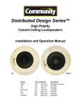
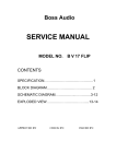
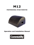
DISTRIBUTED DESIGN SERIES
CEILING LOUDSPEAKERS
BRACKETS AND ACCESSORIES GUIDE
Accessory Part No
Description
D45-CATR
Can Adapter / Trim Ring for D4LP, D4 and D5
D6-CATR
Can Adapter / Trim Ring for D6
D45-FAR
Face Adapter Ring for D4-FO and D5-FO Face-Only Units
D6-FAR
Face Adapter Ring for D6-FO Face-Only Unit
D45-NCB
New Construction Bracket for D4LP, D4 and D5
D6-NCB
New Construction Bracket for D6
D8-NCB
New Construction Bracket for D8
D10-NCB
New Construction Bracket for D10 and D10SUB
DISTRIBUTED DESIGN SERIES CEILING LOUDSPEAKERS
BRACKETS AND ACCESSORIES GUIDE
CAUTION
CONTENTS
Section
Page
Can Adapter / Trim Ring (CATR)
3 to 4
Installation of loudspeakers should only be
performed by trained and qualified
personnel. It is strongly recommended that
a licensed and certified professional structural
engineer approve the mounting design.
Face Adapter Ring (FAR)
5
New Construction Bracket (NCB)
6
Dimensional Drawings
7
WAIVER OF LIABILITY
Compatible Industry Back Cans
8
Whenever Community Light and Sound, Inc. (CLS),
dba Community Professional Loudspeakers is
requested to provide advice or material regarding
the design or installation of its equipment such
advice or material is intended and provided for
information purposes only. The advice or material is
only intended to familiarize the user with various
options for design, coverage and installation. User
expressly agrees that CLS shall not be liable for any
damages, whether in tort, contract, strict liability or
otherwise consequential, incidental or otherwise to
person or property as a result, directly or indirectly,
of the use of any advice or material. The user of any
advice or material provided by CLS assumes all risk
and liability for the use thereof. Without limitation to
the above, CLS does not accept liability or
responsibility for the performance of any
manufacturer, design, method, use, material or
technique employed by the acoustic designer and/or
installation company. All advice, information or
material is subject to field variations and
environmental conditions. All advice, information, or
material given is offered on the assumption that
common or standard practices for installation used
in the construction trades is applied to all phases of
the user’s project. Actual assembly or configuration
must be performed only by persons with knowledge
of mechanical trades and rigging, where applicable.
Any installation method must be certified by a
Professional Engineer licensed in the state in which
assembly or configuration is located.
ABOUT WIRING
Wiring of the loudspeakers is not discussed in this
accessory guide. For information on wiring, please
see the complete Distributed Design Series Ceiling
Loudspeaker Installation and Operation Manual at
www.communitypro.com. The installer must route
the wires and connect them properly before the
loudspeaker installation is completed.
NOTICE: Every effort has been made to ensure
that the information contained in this guide was
complete and accurate at the time of printing.
However, due to ongoing technical advances,
changes or modifications may have occurred that
are not covered in this manual. The latest version
of this manual and the most recent product
information published by Community is always
available at http://www.communitypro.com.
Page 2
CAN ADAPTER / TRIM RING (CATR)
The Distributed Design Series (DDS) Can Adapter/Trim Ring
(CATR) is intended for use when a D-Series ceiling
loudspeaker is being mounted in either an existing oversize
hole in the ceiling or when the entire D-Series ceiling
loudspeaker can assembly is being mounted inside of an
existing, larger, industry standard-type back can.
The next illustration depicts use of the CATR to mount the DDS
ceiling loudspeaker assembly into an existing, significantly
oversize hole (up to 11 inches or 279mm in diameter). In this
case, two CATR’s are deployed, one atop the ceiling and one
below it. When it is not practical or possible to use the
D-Series C-Ring and tile rails for support, a second CATR
may be deployed on the rear of the ceiling to provide a
clamping surface for the loudspeaker. If there is access into
the ceiling (for example, by lifting up an adjacent ceiling tile),
the second CATR may be used without modification.
Using the CATR with an Existing Oversize
Hole
If the DDS ceiling loudspeaker is being fitted into an existing
oversize hole of up to 11 inches (279 mm) in diameter or if
the DDS loudspeaker is being inserted into a previously
installed larger industry back can, then you can use a CATR
to dress the installation.
By using two CATR’s per
loudspeaker you can also add rigidity where it is necessary.
Figure 2:
Dual CATR’s used to strengthen and bridge the
gap across an existing oversize ceiling hole
CATR (Can Adapter Trim Ring)
There are two models of the Can Adapter/Trim Ring. The
D45-CATR is used for retrofit installations of an entire D4LP,
D4 or D5 complete assembly into an existing larger industry
back can or into an existing but oversize ceiling hole. The
D6-CATR does the same for a D6 complete assembly.
Exis ng Ceiling
Tile Rail Bridges
NOTE: Before mounting a loudspeaker into an oversize hole
using the CATR, insert the provided rubber hole plugs into
the four countersunk holes on the CATR that will face
outward. Insert the plugs, pull them through from the rear
side firmly and cut the excess length off of the plugs from
the rear side so that they do not interfere with installation.
You will not need to use the provided 8-32 screws in this
application and you should not need to use the provided
clamp extenders.
CATR (Can Adapter Trim Ring)
D-Series Complete Assembly
(Back Can Showing Drop-StopTM
Tabs)
When using a CATR to mount a D-Series loudspeaker into
an oversize hole, it is recommended that the user also use
the standard tile rails and C-ring behind the ceiling whenever
possible for the best possible weight distribution and
support. Rotate the back can as necessary to ensure all of
the clamps are oriented to contact and compress the C-Ring
to the ceiling tile.
The uppermost CATR rests, lip up, atop the Tile Support Bridge
Rails that come with the DDS Loudspeaker assembly; the
C-Ring Support Plate is not used since it is not large enough to
cover the oversize hole. The Tile Support Bridge Rails provide
extra stability. The CATR on the bottom serves to trim the hole
and it provides a necessary surface for clamping by the flange
of the loudspeaker’s back can.
Figure 1:
Suggested use of CATR and Standard C-Ring
being used in an oversize hole
Exis ng Ceiling
Tile Rail Bridges and C-Ring Support Plate
CATR (Can Adapter Trim Ring)
D-Series Complete Assembly (Back Can
Showing Drop-StopTM Tabs)
Page 3
When there is no access to the upper surface of the ceiling,
the factory-supplied CATR must be modified to provide a
method for getting the bracket through the smaller diameter
hole in the ceiling. The solution is to cut a small 20 to 30
degree arc from the CATR as shown in Figure 3; the larger arc
is needed for thicker ceiling. Tilt the modified CATR, slip its
cutout over the ceiling, and rotate the CATR to position it
appropriately, as illustrated. Make sure that the CATR is
properly centered above the existing hole to provide the best
support possible.
CAN ADAPTER / TRIM RING (CATR) CONTINUED
NOTE: It is not recommended to use this method of
loudspeaker mounting on thin ceilings or those that may sag
over time. Use the C-ring and Tile Support Bridge Rails
whenever possible to help support the load of the loudspeaker.
It is up to the installer to determine if this method of loudspeaker
mounting is appropriate. Improper use of this method can lead
to injury or even death if a poorly supported loudspeaker falls
from the ceiling.
Using the CATR with an Existing Industry
Back Can
You can use a CATR to install a D4, D4LP, D5 or D6
complete loudspeaker assembly, including the back can, into
an existing larger back can. This is the “Adapter” function of
the CATR. Leave the existing back can and its tile rails (if
any) in place. Using the four (4) supplied 8-32 screws,
mount the CATR into the existing back can using the existing
screw inserts on the can, taking care to center the CATR
(Note: you will not need to use the hole plugs in this
application).
Figure 3:
Modification of one CATR in an oversize ceiling hole when
there is no access other than through the hole itself
Before installing the D-Series loudspeaker into the existing
back can you must install the provided Clamping Extenders
onto the ceiling loudspeaker clamping feet. Simply slide the
plastic clamp extenders over the metal clamp. For the best
performance align the outer edge of the extender with the
outer edge of the existing clamp. Make sure to fold the
clamps back against the can before proceeding to install the
loudspeaker. Once that is completed, you can open the
Drop-Stop Tabs slightly, insert the DDS loudspeaker back
can through the CATR, listening for the Drop-Stop Tabs to
snap into position. Then turn the Phillips-head Can-Locking
Clamp Actuator screws in the DDS can so that it is secured
in place, following the same procedure recommended in the
Distributed Design Series Ceiling Installation and Operation
Manual for standard ceiling loudspeaker installation.
Modified CATR being inserted through
the ceiling hole to rest above ceiling
(lip up)
Cut one of the two CATRs as
shown here so that it can be
inserted through the ceiling.
Figure 4:
D45-CATR used to fit an entire assembled D4, D4LP
or D5 into a larger existing back can
Modi ed CATR
Existing Back Can and Tile Rails
Exis ng Hole
CATR (Can Adapter Trim Ring)
CATR (Can Adapter Trim Ring)
D-Series Complete Assembly
(Back Can with Drop-Stop™ Tabs shown)
D-Series Complete Assembly
(Back Can Showing Drop-Stop™
Tabs shown)
Parts Supplied with Can Adapter / Trim Ring (CATR)
D45-CATR
(3) Clamp Extender
(4) Trim Ring Screw Hole Plug
(4) 8-32x1 Oval Head Screw, White
(1) 4.5/5” Can Adapter / Trim Ring
When you then install the complete D-Series loudspeaker
assembly (D4, D4LP, D5 or D6) be sure that all the Drop-Stop
Tabs of the loudspeaker back can will rest on the CATR (i.e.,
don’t align it so that a tab is above the cut-out arc. Obviously
there is no need to cut an arc in the CATR that sits below the
ceiling (lip down), nor would you want to do so for cosmetic
reasons. This concludes the “Trim” function of the CATR.
D6-CATR
(4) Clamp Extender
(4) Trim Ring Screw Hole Plug
(4) 8-32x1 Oval Head Screw, White
(1) 6” Can Adapter / Trim Ring
Page 4
FACE ADAPTER RING (FAR)
The Face Adapter Ring allows a “Face-Only” DDS ceiling
loudspeaker assembly (D4-FO, D5-FO or D6-FO) to be
mounted into an existing industry back can for retrofit
installation. The illustration below shows where the FAR
should be located when implementing this mounting method.
Once the Hole Plugs are inserted you may mount the face to
the FAR. Carefully align the four (4) reinforced screw
bosses on the loudspeaker face with the four (4) metal tabs
sticking out on the FAR. Using the four (4) provided deep
thread screws, screw through the four bosses on the face
and into the metal tabs. Doing this by hand may be difficult.
We recommend that you use a powered screwdriver with a
reasonable amount of torque to help get the screws started
into the metal. Once the screws are started, they will finish
going in easily. Make sure that the outer edge of the plastic
loudspeaker face is seated flush against the FAR all the way
around the loudspeaker after installation is complete.
Figure 5:
Using the FAR to mount DDS loudspeaker faces
(face-only units) into existing industry back cans for
retrofit installations
Existing Back Can and
Tile Rails (if any)
Figure 7:
When mounting the DDS loudspeaker face to the
FAR, carefully align the screw bosses with the
FAR’s metal tabs
FAR (Face Adapter Ring)
Face-Only D-Series Loudspeaker
Installation of the FAR to the back can is identical to
mounting a CATR to the back can (see the CATR section on
pages 3-4). Before mounting the face-only FO model ceiling
loudspeaker face onto the FAR, the supplied Face Hole
Plugs must be installed onto the faces to prevent air leaks.
Failure to install the Face Hole Plugs may compromise the
performance of the loudspeaker. By design, the Face Hole
Plugs fit very tightly and may be somewhat difficult to get into
place. From the front of the face, push the “T” side of the
Plug through one of the oval holes on the loudspeaker face.
Using pliers, finish pulling the hole plug through the face until
the underside of the flat “flange” of the plug is resting flush
on the loudspeaker face and is fully within the groove on the
face. If interference occurs between the loudspeaker face
and the plug flange, it is okay to trim off the long sides of the
flange to reduce the interference.
Parts Supplied with Face-Only Adapter Ring (FAR)
D45-FAR
(3) Face Hole Plug
(4) Trim Ring Screw Hole Plug
(4) 8-32x1 Oval Head Screw, White
(1) 4.5/5” Face Adapter Ring
D6-FAR
(4) Face Hole Plug
(4) Trim Ring Screw Plug
(4) 8-32x1 Oval Head Screw, White
(1) 6.5" Face Adapter Ring
Figure 6:
Before mounting the DDS loudspeaker face into the
existing industry back can, the Face Hole Plugs
MUST be installed on the face to prevent air leaks.
Page 5
NEW CONSTRUCTION BRACKET (NCB)
Community offers four sizes of New Construction Brackets
(NCB) suitable for 4.5-inch, 5-inch, 6.5-inch, 8-inch and
10- inch diameter DDS ceiling loudspeakers. The illustration
below is simply an introduction to the NCB. Please see
Community’s Distributed Design Series Ceiling Loudspeaker
Installation and Operation Manual for information on drywall
ceiling installation methods, pre-installation in a new drywall
ceiling, and inserting the loudspeaker assembly into the
back can.
Figure 8:
Using a New Construction Bracket (NCB) to mount a complete
D4LP, D4, D5, D6, D8, D10 or D10SUB Ceiling Loudspeaker
Assembly in a new drywall ceiling structure
Existing Ceiling Framework
New Construction Bracket
Existing
Drywall
Ceiling
D-Series Back Can
Page 6
ACCESSORY DIMENSIONAL DRAWINGS
The illustrations on this page are NOT drawn to scale. They do accurately depict the dimensions of the various mounting adapters
discussed in this document. Please also see Community’s Distributed Design Series Ceiling Loudspeaker Installation and Operation
Manual for a chart depicting the use of these items with various Distributed Design Series ceiling loudspeaker systems.
New Construction Brackets
Can Adapter / Trim Ring
NOTE: D45-CATR and D6-CATR have the same OD
Face Adapter Ring
Page 7
COMPATIBLE INDUSTRY BACK CANS
The following industry back cans are compatible with Community Distributed Design Series Can Adapter / Trim
Rings (CATR) and Face Adapter Rings (FAR). “ ” indicates that the manufacturer back can is compatible.
D4LP
Back Can Manufacturer
Model
Atlas
D45-FAR
D45-CATR
D4 / D5
D45-FAR
D45-CATR
D6
D6-FAR
D6-CATR
95-8 (All Versions)
95-8-7 (All Versions)
95-8-10 (All Versions)
96-8 (All Versions)
96-8-7
96-8-10
Q408
Lowell
CP84
CP87
CP810
DX58
DX108
RF841
RF871
NOTE: On some "Torsion" model enclosures, the internal torsion hardware may need to be removed prior to installing
the FAR or CATR. Torsion models are sometimes known as "Spring" models and often have a "T" prefix in the model
number, such as the Atlas T95-8.
The following industry back cans are NOT compatible with Community Distributed Design Series
ceiling loudspeaker products and accessories.
Atlas Back Cans: Any 95-4 Series, any 96-4 Series, any 96-6 Series, 95-12, EZ195-8, CS95-8 and any E410 Series
Lowell Back Cans: XCP84, XCP87, XCP810, IX610, IX810, CP4, 8X and DX104.
Community Professional Loudspeakers
333 East Fifth Street, Chester, PA 19013-4511 USA
Phone 610-876-3400 · Fax 610-874-0190
www.communitypro.com
© 2011 Community Professional Loudspeakers
15NOV2011