1
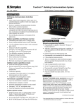
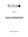
Audix Systems,
Station Road,
Wenden,
Saffron Walden,
Essex,
CB11 4LG.
Telephone: +44(0)1799 540888
Facsimile: +44(0)1799 541618
www.tycosafetyproducts-europe.com
www.audixsystems.co.uk
MSL1000
Monitored Serial Link
Interface
Manual V1.01
MSL1000 User Manual
1. Revision History
Version
1.0
1.01
Modifications
Original issue.
Corrections to jumper tables and setup instructions.
Date
16/05/01
28/06/01
© COPYRIGHT AUDIX SYSTEMS. 2005
DISCLAIMER
This manual contains information that is correct to the best of Audix Systems knowledge. It
is intended to be a guide and should be used as such. It should not be considered as a sole
source of technical instruction, replacing good technical judgement, since all possible
situations cannot be anticipated. If there are any doubts as to exact installation,
configuration and/or use,
call Audix Systems at +44 (0)1799 540888
ACKNOWLEDGEMENTS
All trademarks are recognised
Page 2 of 20
21014 V1.01
MSL1000 User Manual
2. Models Covered
This user manual covers the following equipment
•
•
•
MSL1000 – 16 Channel Monitored Serial Link Interface
TPCHASSIS – Terminal Panel Chassis
TPMSL100 – Termination Board
3. Technical Support
In the unlikely event of you having problems with your MSL1000 please contact our
Customer Services Department.
Audix Systems
Station Road
Wenden
Saffron Walden
CB11 4LG
Tel 01799 540888
Fax 01799 541618
Page 3 of 20
21014 V1.01
MSL1000 User Manual
4. Contents
1.
REVISION HISTORY ...................................................................................................................... 2
2.
MODELS COVERED ...................................................................................................................... 3
3.
TECHNICAL SUPPORT ................................................................................................................. 3
4.
CONTENTS..................................................................................................................................... 4
5.
PROLOGUE.................................................................................................................................... 5
6.
MSL1000 OPERATIONAL DETAILS ............................................................................................. 7
DEFINITIONS ......................................................................................................................................... 7
IMPORTANT SAFETY CONSIDERATIONS ................................................................................................... 7
CONNECTIONS TO ALARM CONTROL SYSTEM:......................................................................................... 7
TERMINATION OF SITE CABLES. .............................................................................................................. 8
SETTING ACTIVE STATE OF ALARM INPUTS. ............................................................................................. 8
DE-ACTIVATING UNUSED ALARM INPUTS.................................................................................................. 8
ALARM INPUT TIMING REQUIREMENTS. .................................................................................................... 8
NON-LATCHING OPERATION OF AN ALARM INPUT. .................................................................................... 8
RESET INPUTS: ..................................................................................................................................... 8
RESET PULSE TIMING REQUIREMENTS:................................................................................................... 9
RESET INPUTS OPERATION: ................................................................................................................... 9
SETTING ACTIVE STATE OF RESET INPUTS............................................................................................... 9
DE-ACTIVATING AN UNUSED RESET INPUT. .............................................................................................. 9
OTHER NOTES ABOUT RESET INPUTS. .................................................................................................... 9
HOW THE CONTACTS ARE MONITORED.................................................................................................. 10
MONITORING RESISTORS ..................................................................................................................... 10
MONITORING THE COMMON FAULT OUTPUT WITH AUDIX FMS............................................................... 10
HOW TO LOCATE THE FAULT WHEN COMMON FAULT OUTPUT IS PRESENT. .............................................. 10
W HAT ARE THE VOLTAGES EXPECTED ON THE INPUT WIRES................................................................... 11
EFFECT OF FAULTS THAT DEVELOP SLOWLY.......................................................................................... 11
7.
SPECIFICATION........................................................................................................................... 12
8.
GENERAL SYSTEM OPERATION............................................................................................... 13
9.
RULES OF OPERATION.............................................................................................................. 14
10.
TABLE OF JUMPER LINKS..................................................................................................... 15
11.
REAR PANEL CONNECTOR PIN-OUTS................................................................................. 17
PIN-OUT FOR MSL1000 FIRE CONTACT MONITORING CARD. D791 PL1 ............................................... 17
PINOUT FOR MSL1000 REAR PANEL TERMINAL BLOCK D791 PL2........................................................ 17
12.
SCHEMATIC DIAGRAMS AND PCB LAYOUTS ..................................................................... 18
MSL1000 W IRING SCHEMATIC
< ADD A4-93476 ON THIS PAGE WITHOUT ITS BORDER > ............... 18
D791 CONTACT MONITORING CARD..................................................................................................... 19
D792A TPMSL100 CARD ................................................................................................................... 20
Page 4 of 20
21014 V1.01
MSL1000 User Manual
5. Prologue
BS 5839 describes a requirement for ‘the voice-alarm system to latch on reciept of
a signal from the fire detection and alarm system until de-latched by a seperate
command from the fire detection and alarm system’. The Audix MSL1000 is a
serial data linked interface for Audix PA VA systems that satisfies this requirement,
with a dc monitored parallel interface for volt-free contacts driven by any fire
detection and alarm system.
This document descibes the intended operation and use of the MSL1000.
The operating principle is to define the contact loop resistance with resistors in
serial and parallel with the contacts, at the contact location. Then with a DC current
drive to the contact loops, monitor the DC voltage with “window detectors” at the
voice-alarm system inputs
Only when the detectors “see” a voltage between the “HI” and “LO” voltage
threshold do they pass on the alarm signal to the voice-alarm equipment, the alarm
signal is “active high”
The HI and LO threshold levels are programmed with jumper links at two alternative
levels to allow monitoring of NO or NC alarm contacts
Two fault conditions will cause a fault to be detected:
1. Open-circuit when the monitored voltage exceeds a reference level
2. Short-circuit when the monitored voltage falls below a reference level
The MSL1000 must be linked to the Master Fault Monitoring System (FMS) which
will report faults detected by the unit.
The detector is designed signal a fault condition to the FMS if power to the unit is
lost
The Output connections of the interface are linked to the serial 485 interface card
and housed into a single 19” rack mountable, 1U chassis.
This connects the alpha, Vector or V32 front-end audio processors, which contain
the emergency message cards.
The data link between the MSL1000 and alpha or Vector is continuously monitored
and its failure is reported to the master FMS.
Whenever the fire alarm contact activates the MSL1000 will send data to the alpha
or Vector and trigger the emergency fire message.
Messages are stored as raw data files and not as simple tone generators, so any
voice and/or alarm message can be recorded and stored on the message cards.
Priorities and routing of messages can be configured within the alpha, Vector or
V32 matrix
Page 5 of 20
21014 V1.01
MSL1000 User Manual
Page 6 of 20
21014 V1.01
MSL1000 User Manual
6. MSL1000 operational details
Definitions
The Unit
Output
MSL1000 Monitored Serial interface
An active high level to the serial to parallel convertor which is
transmitted by the serial link card D439. LED on is the non-alarm
state, the input opto-coupler holds the input low, with high being the
active (alarm) state tranmitted by the MSL1000 to the Alpha or V32
or Vector or similar Voice Alarm System controller.
Alarm Input A dc monitored connection from the fire detection and alarm system,
used to activate the Audix Voice Alarm system
Reset Input A dc monitored connection from the fire detection and alarm system,
used to de-latch the alarm state of the Audix Voice Alarm system.
Fault Output 5V Logic level output from the unit, not driven high in fault condition.
Fault State
An input deemed to be short-circuited or open-circuited, as
detected by the fault monitoring circuits, and thus not able to control
a programmed alarm response.
Important Safety Considerations
The MSL1000 should be supplied from a fuse protected 24V DC supply, the fuse
rating should be 500mA L T.
The MSL1000 and associated equipment must not be exposed to dripping or
splashing.
Connections to Alarm Control System:
The unit will require the following connections to isolated contacts at the fire
detection and alarm system.
1.
One wire per Alarm signal.
2.
One wire for a Common Reset.
3.
One wire common 0V return.
All inputs feature filter/delay circuits to eliminate false triggers.
Figure 1. MSL Schematic (Non Phased Evacuation)
Figure 2. MSL Schematic (Phased Evacuation)
Page 7 of 20
21014 V1.01
MSL1000 User Manual
Termination of site cables.
A ribbon cable from the main MSL1000 chassis connects to a special Termination
Panel fitted to a rail in the the rear of the equipment rack. This panel is Audix
2
Systems part TPMSL100 and allows connection of site cables up to 2.5mm .
There are extra terminals and another ribbon cable connector on the TPMSL100 to
accomodate the System Fault outputs from an Audix Systems FMS system.
The terminal block arrangement is shown in a later section of this manual, for easy
installation it is silkscreened on to the PCB just below the terminal blocks.
Setting active state of alarm inputs.
For all inputs the operational active state will be collectively programmed as
‘normally open’ or ‘normally closed’ using jumpers.
Fit J1, J3/1-2, leave J2 open for NC mode. or Fit J2, J3/2-3, leave J1 open for
NO mode.
Each input in use, should have its ‘Input Active’ jumper fitted to provide monitoring
current: Fit J12 for input 1, J22 for input 2, J32 for input 3 etc.
There is a complete listing of all the jumpers later in this manual.
De-activating unused alarm inputs.
Any input not in use, should have its ‘Input Active’ jumper removed.
Remove J12 for input 1, J22 for input 2, J32 for input 3 etc.
In the open or unjumpered state, the input will be inactive, and must not be
programmed as part of the alarm system. No connection should be made to the
input terminals, if a monitored contact is accidentally connected then a fault will be
indicated.
Alarm Input timing requirements.
The Reset Input should be inactive before an Alarm Input changes to the active
state.
The Fire Detection system should maintain the Alarm Input(s) in an active state, for
the duration of the alarm period.
To cancel the alarm, the Alarm Input is deactivated immediately before a reset
pulse is applied at the reset input.
See “General System Operation” a later section of this manual, for a description of
operation with a Fire Alarm system.
Non-latching operation of an Alarm input.
The second jumper link on each input channel allows latching mode to be defeated
for that input. In general these links will not be fitted on BS5839 compliant systems.
For non-latching operation fit J11 for input 1, J21 for input 2 non, J31 for input 3
etc.
Reset Inputs:
There are two reset inputs, operation of each is identical.
Page 8 of 20
21014 V1.01
MSL1000 User Manual
The Reset Input should be driven (with a pulsed signal) by the fire detection and
alarm equipment.
Reset Pulse Timing requirements:
The Reset Input should be driven to its active state for 2 seconds minimum,
following the change of state of any Alarm Input from active to inactive state.
Reset Inputs Operation:
When Reset inputs are in the inactive state, or in a recognised fault state; each
output will become active when the associated input connection goes into activate
state.
When the Reset inputs are in the inactive state, or in a recognised fault state ; any
active output will remain active, even if the corresponding alarm input goes into a
faulty state.
The Reset Input will be ineffective when in s/c fault state, or in o/c fault state.
When a Reset Input is in a recognised fault state it will not be possible to silence
the alarms by deactivating the alarm inputs.
An active Output will remain active if its Input is active and a Reset input is active
An active Output will remain active if its input goes directly into a fault state, while
the Reset Input is in inactive state or fault state.
Setting active state of reset inputs.
The active state of the Reset Inputs follows the collectively programmed state for
the alarm inputs (i.e. ‘normally open’ or ‘normally closed’ using jumpers.)
The reset inputs in use must have thier ‘Input Active’ jumpers fitted:
Fit J301 if Reset Input 1 is in use, fit J311 if Reset Input 2 is in use.
De-activating an unused reset input.
The unused reset input should have its ‘Input active’ jumper left open.
In the open or unjumpered state, the input will be inactive, and no connection
should be made to the input terminals. If monitored contact is connected then a
fault will be indicated.
Remove J301 if Reset Input 1 is not used.
Remove J311 if Reset Input 2 is not used.
Other notes about reset inputs.
The second monitored Reset input may optionally be wired to a manually operated
switch or to key-switch on the front panel of the unit or at some remote location.
When a Reset Input is held in the Active State the operation of the unit will appear
non-latching. This is just how it works but is not the best way to achieve overall
non-latching operation. If non-latching is is required it is recommended to disable
the reset inputs and select non-latching operation for all of the alarm inputs as
described earlier in this manual.
Page 9 of 20
21014 V1.01
MSL1000 User Manual
How the contacts are monitored.
Each input, including reset inputs will monitor its input connection for o/c and s/c
failure.
Each input has 4 states, defined by voltage levels: o/c fault, s/c fault, active, and
inactive.
Any Input detecting a fault state will cause an active low signal on the ‘common
fault’ output from the unit.
Each input connection must be fitted with the specified monitoring resistors located
at the fire detection equipment end of the connection.
Failure of any or the power rails within the unit will cause an active low signal on the
‘common fault’ output from the unit.
Any Alarm or Reset input that is deactivated ( no jumper fitted) will cause a
common fault output, if monitor resistors are connected to the input terminals.
Monitoring resistors
Specified end of line resistors, as supplied with MSL1000:
R in series with contacts:
910Ω 1% 100ppm 0.3W metal film
R in parallel with contacts:
3KΩ 1% 100ppm 0.3W metal film
Figure 3. MSL Wiring Details
This gives the following resistance readings:
Switch Closed state circuit resistance
= 910 Ω.
Switch Open state circuit resistance
= 3.91 kΩ ( 910Ω +3.0 kΩ)
Control Line Short Circuit
=0Ω
Control Line Open Circuit
=∞Ω
Monitoring the Common Fault Output with Audix FMS.
The Common Fault output should be monitored using an input of a Audix VT704
card in an Audix FMS. The VT704 should be set to indicate a fault when the
common fault output drops below 4.0 Volts. The input pull-up resistor on the VT704
must be disconnected with the appropriate jumper link setting.
If the Common Fault output is used to drive Fault Monitoring Systems other than
Audix FMS be aware that this output does not sink current in the fault state when
power fails to the MSL1000.
How to locate the fault when common fault output is present.
As the diagnostic LEDs are not visible when the chassis is closed, the easiest way
to identify faulty inputs is to measure the voltages on the input terminals with a DC
voltmeter.
Page 10 of 20
21014 V1.01
MSL1000 User Manual
What are the voltages expected on the input wires.
Each input has 4 states, defined by voltage levels: o/c fault, s/c fault, active, and
inactive.
Contact Status
Fault condition
Alarm/Active
Idle/inactive
Fault condition
Input voltage range:
N.C. mode
Over 12.3V
6.7 V to 12.3V
Nominal 5.4V
Less than 4.0V
Input voltage range:
N.O. mode
Over 12.3V
4.0V to 8.0V
Nominal 10.4V
Less than 4.0V
The voltages in the table assume the onboard regulator is exactly 15 Volts. If the regulator gives a
different voltage within its expected tolerance range then the thresholds which are derived from this
voltage will vary pro-rata.
Effect of faults that develop slowly.
Certain slowly developing faults may be seen as temporary false alarm signals,
these will of course latch if the Reset Input is in inactive state or fault state.
In practice an s/c fault is more likely to develop slowly than a o/c fault; a typical
cause of this problem is moisture soaking into a badly sealed mineral insulated
cable.
A false alarm will not normally be generated when a fault warning is given for a
slowly developing s/c fault if the Fire Alarm Interface is operated in Normally Closed
mode, although the idle current is slightly higher in this mode. A decision must be
made during system design which mode of operation best suits the application.
The monitoring circuitry is designed to avoid another problem associated with
Normally Closed mode; The leakage current on the cable should trigger a fault
condition before it becomes too large to prevent the voltage reaching the alarm
threshold should the contact open to signal a true alarm signal. The voltage
thresholds are set differently in NC mode specifically to avoid this problem.
Another problem addressed in the design is the effect of a slowly developing fault
on a reset input, which may pass through the reset active state, during which time
the latching operation would be ineffective. This is why it is most important for the
alarm inputs to be maintained during alarm conditions, as described in the general
system operation section, this then gives the system the greatest immunity from
failure to generate an alarm.
Page 11 of 20
21014 V1.01
MSL1000 User Manual
7. Specification
Alarm inputs .
16
Reset inputs
2
Input activation collectively programmed.
Either NO or NC
Inputs individually programmable
Active or Disabled
Inputs individually programmable
Latching or Non-latching
Input connection monitoring.
O/C and S/C failures.
Alarm is not activated by inputs detecting faulty input
connections.
Certain slow faults excepted.
RS485 interface to VA matrix
PMCV 16 protocol.
Single Logic level fault O/P
Driven high for no faults.
(greater than 4V)
Fault output, high state source current
6 mA at 4V o/p
Fault output low state sink current ( with power failed )
0 mA
Front panel fault indicators.
None
Internal diagnostic LEDs per alarm input:
Input in fault state.
Internal diagnostic LEDs per reset input:
Input in fault state.
Internal diagnostic LED:
Reset input active, one LED
for both reset inputs.
Power supply voltage required:
20 – 28V DC
24V DC recommended
In normal idle state the MSL1000 with all inputs active:
200mA from a 24V
Power supply protection fuse rating.
500mA L T
Power consumption:
5W max.
Page 12 of 20
21014 V1.01
MSL1000 User Manual
8. General System Operation
Figure 4. Timing Diagram For Single Message Operation
Figure 4 Shows a simple single message system, The fire alarm panel switches the
contact which activates the voice alarm message to be broadcast. The fire panel
should maintain the contact for the duration of the alarm condition. When the alarm
contact is deactivated. The fire panel must pulse on the reset line for 2sec
(nominal) which will switch off the alarm message.
Figure 5. Timing Diagram for Multiple Message Operation
Figure 5 shows a system with Alert and Evacuation Messages. As with the previous
system the Fire panel switches an alarm contact which activates the voice alarm to
broadcast the Alert message. Some time later the fire panel switches the
evacuation contact. Due to the matrix having priorities on each message the
Evacuation message (which is a higher priority than the alert) will now be broadcast.
As before the fire panel must maintain the contact for the duration of the alarm. To
stop the broadcast of messages. The fire panel must deactivate the alarm
contacts, and pulse the Reset line for 2 seconds.
Page 13 of 20
21014 V1.01
MSL1000 User Manual
Figure 6. Zoned Evacuation Timing Diagram
Figure 6 shows a multi-zoned evacuation system with both Evacuation and alert
messages.
The fire panel switches the alert contact for zone 1. This causes the Alert message
to be broadcast to zone1 . Some time later the fire panel switches the alert contact
for zone 2. The alert message will now be broadcasting to both zone 1 and 2.
After this the fire panel switches the zone to Evac, Due to the priority in the matrix
the Evacuation message over rides the alert and is broadcast to zone 1, the alert
message will still be broadcasting in zone 2. Some time after this the Evac and
Alert from zone 1 are deactivated b the fire alarm, the reset should be pulsed on for
2 second to stop the broadcast of message to zone 1. As the Zone 2 Alert contact
is still activated during the reset for the zone 1 contacts. The output state will not
change and the alert message will still be broadcast to zone 2. Finally when the
zone 2 alert is deactivated by the fire panel the reset contact must be pulsed to
stop the alert broadcast to zone 2.
9. Rules of operation.
1) The fire panel should maintain the contact for the duration of the alarm
condition
2) Whenever an output form the Fire Panel is switched to the non alarm state, the
reset output must be pulsed for 2 seconds.
Page 14 of 20
21014 V1.01
MSL1000 User Manual
10. Table of Jumper links.
J12
J22
J32
J42
J52
J62
J72
J82
J92
J102
J112
J122
J132
J142
J152
J162
Activate input 1
Activate input 2
Activate input 3
Activate input 4
Activate input 5
Activate input 6
Activate input 7
Activate input 8
Activate input 9
Activate input 10
Activate input 11
Activate input 12
Activate input 13
Activate input 14
Activate input 15
Activate input 16
Fit if input is used.
J11
Non-latching input 1
J21
J31
J41
J51
J61
J71
J81
J91
J101
Non-latching
Non-latching
Non-latching
Non-latching
Non-latching
Non-latching
Non-latching
Non-latching
Non-latching
10
Non-latching
11
Non-latching
12
Non-latching
13
Non-latching
14
Non-latching
15
Non-latching
16
Open for latching mode.
mode.
J111
J121
J131
J141
J151
J161
J1
NC mode
J3/2-3
NC mode
J2
NO mode
input 2
input 3
input 4
input 5
input 6
input 7
input 8
input 9
input
Open if input not used.
Fit for non-latch
input
input
input
input
input
input
Fit if interfacing with Normally Closed contacts
Open if interfacing with Normally Open contacts
Fit if interfacing with Normally Closed contacts
Open if interfacing with Normally Open contacts
Note This is labelled wrongly as NO on PCB
iss.B
Fit if interfacing with Normally Open contacts
Open if interfacing with Normally Closed
Page 15 of 20
21014 V1.01
MSL1000 User Manual
J3/1-2
J301
J311
NO mode
Activate Reset 1 input
Activate Reset 2 input
contacts
Fit if interfacing with Normally Open contacts
Open if interfacing with Normally Closed
contacts
Note This is labelled wrongly as NC on PCB
iss.B
Fit if Reset 1 is used. Open if Reset 1 not used
Fit if Reset 2 is used. Open if Reset 2 not used
Page 16 of 20
21014 V1.01
MSL1000 User Manual
11. Rear panel connector pin-outs
Pin-out for MSL1000 Fire Contact Monitoring card. D791 PL1
Pin/
Cor
e
1
2
3
4
5
6
7
8
9
10
11
12
13
14
15
16
17
18
19
20
21
22
23
24
25
26
Signal
name
Description
0V
0V
IP 1
IP 2
IP 3
IP 4
IP 5
IP 6
IP 7
IP 8
0V
0V
IP 9
IP 10
IP 11
IP 12
IP 13
IP 14
IP 15
IP 16
0V
0V
RES_1
RES_2
spare 25
spare 26
Common 0V return
Common 0V return
Monitored contact input 1
Monitored contact input 2
Monitored contact input 3
Monitored contact input 4
Monitored contact input 5
Monitored contact input 6
Monitored contact input 7
Monitored contact input 8
Common 0V return
Common 0V return
Monitored contact input 9
Monitored contact input 10
Monitored contact input 11
Monitored contact input 12
Monitored contact input 13
Monitored contact input 14
Monitored contact input 15
Monitored contact input 16
Common 0V return
Common 0V return
Monitored Reset Input 1
Monitored Reset Input 2
Spare wire to terminal panel
Spare wire to terminal panel
Pinout for MSL1000 Rear Panel Terminal Block D791 PL2.
Pin/
Cor
e
Signal
name
1
2
3
4
5
6
0V
24V
/FAULT
D+
D–
Data SCR
Description
(Note: Pin 1 is LHS viewed from REAR of
MSL1000)
0V DC supply return (BLACK)
24V DC supply input (RED)
Logic Level Fault Output (>2.5V = OK, <2.5V = FAULT)
Data Signal +ve (GREEN)
Data Return –ve (YLW)
Page 17 of 20
21014 V1.01
MSL1000 User Manual
12. Schematic Diagrams and PCB layouts
MSL1000 Wiring schematic
Page 18 of 20
21014 V1.01
MSL1000 User Manual
D791 Contact Monitoring Card
Page 19 of 20
21014 V1.01
MSL1000 User Manual
D792a TPMSL100 Card
Pinouts for TPMSL100: 10W ribbon cable for FMS Fault outputs
Pin/Core
Signal
Description
1
NF_NC
New Fault contact (NO when relay not powered)
2
NF_W
New Fault contact (Wiper)
3
NF_NO
New Fault contact (NC when relay not powered)
4
SF_NC
System Fault contact (NO when relay not powered)
5
SF_W
System Fault contact (Wiper)
6
SF_NO
System Fault contact (NC when relay not powered)
7
ACC
Fault Accept contact i/p
8
0V
OV return for Accept contact
9
== +5V ==
= DO NOT CONNECT = Internal 5V rail used for test jigs
Page 20 of 20
21014 V1.01