1
Crestron ST-VS
Video Sensor Module
NOTE: Most 4-conductor phone cables are wired in a crisscross fashion and are not
compatible with Crestron equipment.
If the power pack is attached when the module is part of a Cresnet system, power is
drawn from the power pack. The module does not draw from the network power, but
the network power remains chained.
VIDEO 1 - 4
There are four sets of independent video pass through connectors. These eight RCA
connectors (two per video signal) connect to the (up to) four independent sources
that require sensing.
Indicators
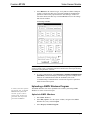
There are six LED indicators located on the front panel of the ST-VS. Each has a
silk-screened label. Refer to the illustration and descriptions below.
ST-VS Indicators
PWR (Power)
This LED illuminates when 12 volts (from the external power pack) or 24 volts DC
(from the network) is supplied to the ST-VS.
NET
This LED illuminates when communication between Cresnet and the ST-VS is
established. Illumination indicates that the SIMPL Windows program currently
loaded has a network device defined at the same network ID as the ST-VS.
VIDEO 1 - 4
These four LEDs illuminate when a video signal on the respective VIDEO connector
exceeds the minimum requirements (threshold) for signal detection.
Industry Compliance
As of the date of manufacture, the ST-VS has been tested and found to comply with
specifications for CE marking.
NOTE: This device complies with part 15 of the FCC rules. Operation is subject to
the following two conditions: (1) these devices may not cause harmful interference,
and (2) these devices must accept any interference received, including interference
that may cause undesired operation.
Operations Guide – DOC. 5767A
Video Sensor Module: ST-VS • 5