1
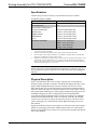
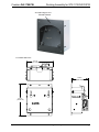
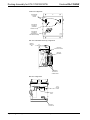
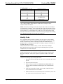
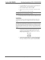
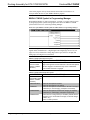
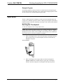
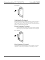
Crestron DA-1700CW Docking Assembly for STX-1700CW/CXPW Operations and Installation Guide This document was prepared and written by the Technical Documentation department at: Crestron Electronics, Inc. 15 Volvo Drive Rockleigh, NJ 07647 1-888-CRESTRON All brand names, product names and trademarks are the property of their respective owners. ©2005 Crestron Electronics, Inc. Crestron DA-1700CW Docking Assembly for STX-1700CW/CXPW Contents Docking Assembly for STX-1700CW/CXPW: DA-1700CW 1 Introduction ............................................................................................................................... 1 Functions and Features ................................................................................................ 1 Specifications .............................................................................................................. 2 Physical Description.................................................................................................... 2 Industry Compliance ................................................................................................... 5 Setup .......................................................................................................................................... 5 Network Wiring........................................................................................................... 5 Identity Code ............................................................................................................... 6 Installation ................................................................................................................... 7 Programming Software .............................................................................................................. 9 Earliest Version Software Requirements for the PC ................................................... 9 Programming with SIMPL Windows ........................................................................ 10 Operation ................................................................................................................................. 13 Docking the Touchpanel............................................................................................ 13 Undocking the Touchpanel........................................................................................ 14 Problem Solving ...................................................................................................................... 16 Troubleshooting......................................................................................................... 16 Further Inquiries ........................................................................................................ 18 Future Updates .......................................................................................................... 18 Return and Warranty Policies .................................................................................................. 19 Merchandise Returns / Repair Service ...................................................................... 19 CRESTRON Limited Warranty................................................................................. 19 Operations and Installation Guide - DOC. 6104A Contents • i Crestron DA-1700CW Docking Assembly for STX-1700CW/CXPW Docking Assembly for STX-1700CW/CXPW: DA-1700CW Introduction Functions and Features The DA-1700CW docking assembly is wall-mounted hardware that is used to dock a Crestron STX-1700CW or STX-1700CXPW color touchpanel. Used with the BB-1700CW back box (sold separately), the DA-1700CW provides operating power, hard-wire communications with a standard Crestron remote control system (herein referred to as the Cresnet system), and recharges the Crestron High Performance Rechargeable Power Pack (ST-BTPN) of the docked touchpanel. The DA-1700CW unlatches the touchpanel electrically via the control system program. When the touchpanel is unlatched, it snaps outward slightly, and then may be removed by hand. The control system program defines the method of unlatching. Provisions have also been incorporated to allow the touchpanel to be unlatched manually. Functional Summary • • • Docks the STX-1700CW or STX-1700CXPW Enables Cresnet communication between control system and touchpanel Recharges touchpanel battery When not docked in the DA-1700CW, the touchpanel is a handheld, RF, 2-way wireless transceiver that communicates through an RF transceiver/gateway, (sold separately) to the Cresnet system. The 2-way communications provide delivery of commands to the Cresnet system and provide dynamic onscreen feedback for realtime confirmation of commands. Up to 15 touchpanels can communicate with one gateway. For detailed information about the operation and programming of the touchpanels themselves, refer to the latest version of the Operations Guide for the STX-1700CW (Doc. 6228) or the STX-1700CXPW (Doc. 6249) available from the Crestron website (http://www.crestron.com/manuals). Operations and Installation Guide - DOC. 6104A Docking Assembly for STX-1700CW/CXPW: DA-1700CW • 1 Docking Assembly for STX-1700CW/CXPW Crestron DA-1700CW Specifications The table below provides a summary of specifications for the DA-1700CW. Specifications of the DA-1700CW SPECIFICATION DETAILS Cresnet Power Usage Default Network ID Control System Update Files 2-Series Control System CEN/CN-TVAV CNMSX-AV/PRO CNRACKX/-DP ST-CP Dimensions and Weight 16 Watts (0.67 Amps @ 24 VDC) 51 1 2,3,4 Version C2-2004.CUZ or later Version 5.10.13V.UPZ or later Version 5.10.11X.UPZ or later Version 5.10.11W.UPZ or later Version 4.02.02-S.UPZ or later Height: 6.51 in (16.54 cm) Width: 5.57 in (14.14 cm) Depth: 3.56 in (9.05 cm) Weight: 3.21 lb (1.46 kg) 1. 2. 3. 4. Value shown is for docking station with no touchpanel docked. With docked touchpanel, power usage is 34 watts (1.42 Amps @ 24 VDC). The latest versions can be obtained from the Crestron website. Refer to NOTE below. Crestron 2-Series control systems include the AV2 and PRO2. Consult the latest Crestron Product Catalog for a complete list of 2-Series control systems. Filenames for CNX and ST-CP update files have a UPZ extension. Files on the website may be .zip or self-extracting .exe files containing the .cuz or .upz file. All can be obtained from the Downloads section of the Crestron website. To avoid program problems, make sure you are using the update file with the correct suffix letter (e.g., S, V, W, X) NOTE: Crestron software and any files on the website are for Authorized Crestron dealers and Crestron Authorized Independent Programmers (CAIP) only. New users may be required to register to obtain access to certain areas of the site (including the FTP site). Physical Description Refer to the illustrations on the next two pages. The physical view illustrates the docking assembly mounted in a back box. The dimensions diagram provides overall height, width, and depth dimensions of the DA-1700CW. The front view of the DA-1700CW shows the two mechanical hooks used to latch the touchpanel and six electrical contacts. The upper two electrical contacts are for Cresnet system Y and Z data signals and the remaining four contacts supply touchpanel operating power and ST-BTPN recharging. The side view diagram shows the manual unlatch tab (accessible through the supplied decorative faceplate), the latching lever and hooks, and the electrical unlatch solenoid. At the rear of the DA-1700CW is the standard Cresnet 4-wire, network port. The port provides the Cresnet 24 volts direct current (VDC) operating power, communications, and ST-BTPN recharging power to the DA-1700CW. Supplied with the DA-1700CW, but not shown, are a decorative front panel, manual unlatch access hole plug (part number 2002405) and four hex screws (part number 2007227). Four Phillips screws (2007217) to secure the unit to the BB-1700CW back box are also supplied. 2 • Docking Assembly for STX-1700CW/CXPW: DA-1700CW Operations and Installation Guide - DOC. 6104A Crestron DA-1700CW Docking Assembly for STX-1700CW/CXPW DA-1700CW Physical View Manual Release DA-1700CW Dimensions 5.57 in (14.14 cm) 3.56 in (9.05 cm) 6.51 in (16.54 cm) Operations and Installation Guide - DOC. 6104A Docking Assembly for STX-1700CW/CXPW: DA-1700CW • 3 Docking Assembly for STX-1700CW/CXPW Crestron DA-1700CW Front View Components TOUCHPANEL LATCHING HOOKS ELECTRICAL CONTACTS (CRESNET Y DATA & Z DATA) ELECTRICAL CONTACTS (OPERATING & RECHARGE POWER) Side View (with Partial Cut-Away) Components MANUAL UNLATCH TAB LATCHING LEVER & HOOKS UNLATCH SOLENOID SOLENOID ELECTRICAL CONNECTORS Rear View Components LATCH RETURN SPRING UNLATCH LEVER CRESNET CONNECTOR 4 • Docking Assembly for STX-1700CW/CXPW: DA-1700CW Operations and Installation Guide - DOC. 6104A Crestron DA-1700CW Docking Assembly for STX-1700CW/CXPW Industry Compliance As of the date of manufacture, this unit has been tested and found to comply with specifications for CE marking and standards per EMC and Radiocommunications Compliance Labelling. NOTE: This device complies with part 15 of the FCC rules. Operation is subject to the following two conditions: (1) this device may not cause harmful interference, and (2) this device must accept any interference received, including interference that may cause undesired operation. Setup Network Wiring CAUTION: In order to ensure optimum performance over the full range of your installation topology, Crestron Certified Wire, and only Crestron Certified Wire, should be used. Failure to do so may incur additional charges if support is required to identify performance deficiencies as a result of using improper wire. CAUTION: Use only Crestron power supplies for Crestron equipment. Failure to do so could cause equipment damage or void the Crestron warranty. CAUTION: Provide sufficient power to the system. Insufficient power can lead to unpredictable results or damage to the equipment. Please use the Crestron Power Calculator to help calculate how much power is needed for the system. <http://www.crestron.com/dealer-tech_resources/power_calculator.asp> NOTE: When installing network wiring, refer to the latest revision of the wiring diagram(s) appropriate for your specific system configuration, available from the Crestron website. When calculating the wire gauge for a particular Cresnet run, the length of the run and the Cresnet power usage of each network unit to be connected must be taken into consideration. If Cresnet units are to be daisy-chained on the run, the Cresnet power usage of each unit to be daisy-chained must be added together to determine the Cresnet power usage of the entire chain. If the unit is a home-run from a Crestron system power supply network port, the Cresnet power usage of that unit is the Cresnet power usage of the entire run. The length of the run in feet and the Cresnet power usage of the run should be used in the following resistance equation to calculate the value on the right side of the equation. Resistance Equation R< 40,000 LxP Where: R = Resistance (refer to the following table). L = Length of run (or chain) in feet. P = Cresnet power usage of entire run (or chain). The required wire gauge should be chosen such that the resistance value is less than the value calculated in the resistance equation. Refer to the following table. Operations and Installation Guide - DOC. 6104A Docking Assembly for STX-1700CW/CXPW: DA-1700CW • 5 Docking Assembly for STX-1700CW/CXPW Crestron DA-1700CW Wire Gauge Values RESISTANCE (R) WIRE GAUGE 4 16 6 18 10 20 15 22 13 Doubled CAT5 8.7 Tripled CAT5 NOTE: All Cresnet wiring must consist of two twisted-pairs. One twisted pair is the +24V conductor and the GND conductor and the other twisted pair is the Y conductor and the Z conductor. NOTE: When daisy-chaining Cresnet units, strip the ends of the wires carefully to avoid nicking the conductors. Twist together the ends of the wires that share a pin on the network connector, and tin the twisted connection. Apply solder only to the ends of the twisted wires. Avoid tinning too far up the wires or the end becomes brittle. Insert the tinned connection into the Cresnet connector plug and tighten the retaining screw. Repeat the procedure for the other three conductors. Identity Code Every equipment and user interface within the network requires a unique identity code (Net ID). These codes are two-digit hexadecimal numbers from 03 to FE. The Net ID of each unit must match an ID code specified in the SIMPL Windows program. Refer to “Setting the Net ID in Device Settings” on page 11 for details of the SIMPL Windows procedure. The Net ID of the DA-1700CW is factory set to 51. The Net IDs of multiple DA-1700CWs in the same system must be unique and changed from a personal computer (PC) via Crestron Viewport. NOTE: For detailed information on establishing communication between the PC and the Control System, refer to the latest version of the 2-Series Control System Reference Guide (Doc. 6256) or the respective Operations Guide for the control system. Complete the following steps to change the Net ID. 1. Ensure that the DA-1700CW is the only device connected to the control system. 2. Open the Crestron Viewport. 3. From the Viewport menu, select Functions | Set Network ID. The software checks the baud rate and then opens the "Set Network ID" window. 4. In the “Set Network ID” window, select the DA-1700CW from the Current Network Devices text window. 5. From the Choose the new network ID for the selected device (Hex): text box, select the new Net ID for the DA-1700CW. 6 • Docking Assembly for STX-1700CW/CXPW: DA-1700CW Operations and Installation Guide - DOC. 6104A Crestron DA-1700CW Docking Assembly for STX-1700CW/CXPW 6. Click the Set ID button to initiate the change. This should display the confirmation message, “ID command has been sent”. 7. In the "Command Complete" window, click OK. 8. In the Current Network Devices text window, verify the new Net ID code. 9. In the "Set Network ID" window, click Close. NOTE: The new Net ID code may also be verified by selecting Diagnostic | Report Network Devices in the Viewport (alternately, select F4). 10. Repeat this procedure for each DA-1700CW to be added to the system. Installation To install the DA-1700CW, complete the following installation procedure in the order provided. Tools required are a #2 Phillips screwdriver and a 5/64-inch hex wrench. NOTE: This procedure is performed only after the BB-1700CW back box (optional) has been installed. Make sure that the back box is installed inward of the face of the gypsum board to accommodate the distance between the back box and the front panel. For further information, refer to the latest revision of the BB-1700CW Installation Guide (Doc. 6105). The latest version can be obtained from the Crestron website. 1. Position the DA-1700CW to the back box and connect the Cresnet wiring to the rear port using the supplied connector. The rear port connections are shown in the following graphic. Refer to “Network Wiring” on page 5 if necessary. 2. As shown in the following illustration, position the DA-1700CW into the back box. Install four Phillips screws (supplied) to finger-tight then, using a #2 Phillips screwdriver, tighten an additional 1/8-turn. Operations and Installation Guide - DOC. 6104A Docking Assembly for STX-1700CW/CXPW: DA-1700CW • 7 Docking Assembly for STX-1700CW/CXPW Crestron DA-1700CW Install DA-1700CW 3. As shown in the following illustration, position the front panel to the DA-1700CW. Install four hex screws (supplied) to finger-tight then, using a 5/64-inch hex wrench, tighten an additional 1/8-turn. Install Front Panel 8 • Docking Assembly for STX-1700CW/CXPW: DA-1700CW Operations and Installation Guide - DOC. 6104A Crestron DA-1700CW Docking Assembly for STX-1700CW/CXPW 4. As shown below, install the access hole plug into the access hole. Install Access Hole Plug Programming Software Have a question or comment about Crestron software? Answers to frequently asked questions (FAQs) can be viewed in the Online Help section of the Crestron website. To post a question or view questions you have submitted to Crestron’s True Blue Support, log in at http://support.crestron.com/. First-time users will need to establish a user account. Earliest Version Software Requirements for the PC NOTE: Crestron recommends that you use the latest software to take advantage of the most recently released features. The latest software is available from the Crestron website. The following are recommended software version requirements for the PC: • SIMPL Windows version 2.02.11 with Library Update 178 or later. Requires SIMPL+ Cross Compiler version 1.1. • Crestron Database version 15.7.5 or later. Operations and Installation Guide - DOC. 6104A Docking Assembly for STX-1700CW/CXPW: DA-1700CW • 9 Docking Assembly for STX-1700CW/CXPW Crestron DA-1700CW Programming with SIMPL Windows NOTE: The following are acceptable file extensions for programs that include a DA-1700CW, developed for specific control system types: .smw projectname.smw (source file) .spz projectname.spz (compiled file for 2-series) .bin projectname.bin (compiled file for CNX generation) .csz projectname.csz (compiled file for CNX generation with SIMPL+) .ush projectname.ush (compiled file for CNX generation with SIMPL+ header file) .usp projectname.usp (source code module for SIMPL+) SIMPL Windows is Crestron's software for programming Crestron control systems. It provides a well-designed graphical environment with a number of workspaces (i.e., windows) in which a programmer can select, configure, program, test, and monitor a Crestron control system. SIMPL Windows offers drag and drop functionality in a familiar Windows® environment. NOTE: The following assumes that the reader has knowledge of SIMPL Windows. If not, refer to the extensive help information provided with the software. NOTE: In the following description, the PRO2 control system is used. This section explains how to create a SIMPL Windows program that includes a DA-1700CW. Configuration Manager is where programmers “build” a Crestron control system by selecting hardware from the Device Library. In Configuration Manager, drag the PRO2 from the Control Systems folder of the Device Library and drop it in the upper pane of the System Views. The PRO2 with its associated communication ports is displayed in the System Views upper pane. PRO2 System View The System Views lower pane displays the PRO2 system tree (refer to graphic below). This tree can be expanded to display and configure the communications ports. Expanded PRO2 System Tree 10 • Docking Assembly for STX-1700CW/CXPW: DA-1700CW Operations and Installation Guide - DOC. 6104A Crestron DA-1700CW Docking Assembly for STX-1700CW/CXPW C2Net-Device Slot in Configuration Manager The C2Net-Device Slot can accept a DA-1700CW. Once a DA-1700CW is configured in a C2Net-Device Slot, the slot allows Cresnet communication between the DA-1700CW and the control system. NOTE: Refer to the appropriate touchpanel manual for information on developing a program that includes a touchpanel to be docked in the docking station. In Configuration Manager, drag the BB/DA-1700CW from the Cresnet Control Modules | Cresnet I/O Control & Other Modules folder of the Device Library and drop it on the PRO2 C2Net-Device slot in System Views. The System Views upper pane displays the BB/DA-1700CW device icon below the PRO2 graphic. The PRO2 system tree displays the BB/DA-1700CW in Slot 9, with a default Net ID of 51. Refer to the graphic below. C2Net Device, Slot 9 Setting the Net ID in Device Settings Double-click the BB/DA-1700CW icon in the upper pane to open the “Device Settings” window (shown below). This window displays BB/DA-1700CW device information. The Net ID can be changed in this window using the Net ID tab. “Device Settings” Window NOTE: SIMPL Windows automatically changes Net ID values of a device added to a program if a duplicate device or a device with the same default Net ID already Operations and Installation Guide - DOC. 6104A Docking Assembly for STX-1700CW/CXPW: DA-1700CW • 11 Docking Assembly for STX-1700CW/CXPW Crestron DA-1700CW exists in the program. Always ensure that the network device Net IDs set via Viewport match the ones in your SIMPL Windows program. BB/DA-1700CW Symbol in Programming Manager Programming Manager is where programmers “program” a Crestron control system by assigning signals to symbols. The graphic below shows the BB/DA-1700CW symbol in the Detail View of the Programming Manager. Detail View of the BB/DA-1700CW Symbol in SIMPL Windows’ Programming Manager NOTE: All signals listed in the tables below and on the next page are DIGITAL signals unless noted otherwise. A digital signal can be high (logic level of 1), low (logic level of 0), and also have rising edge (when it goes from low to high) and falling edge (from high to low) transitions. BB/DA-1700CW Symbol Input Description INPUT UNLATCH (Unlock in earlier versions of SIMPL Windows.) FUNCTION(S) Edge sensitive. Unlatches the back box for 5-seconds when the edge of the signal is received. After the 5-seconds has expired, the latch engages. The back box may not be unlatched for 1-second after the latch is engaged. BB/DA-1700CW Symbol Output Descriptions OUTPUTS FUNCTION(S) UNLATCHED 1 when the latch is open, 0 when the latch is closed. (Unlock-FB in earlier versions of SIMPL Windows.) PANELPRESENT 1 when the touchpanel is docked, 0 when the touchpanel is not docked. 1 when the touchpanel is docked and the ST-BTP is charging, CHARGING 0 otherwise (i.e. done charging, touchpanel not docked). CHARGEDONE 1 when the touchpanel is docked and charging is complete, 0 otherwise (i.e. still charging, touchpanel not present). CHARGEFAULT 1 when there is a charge fault (i.e. hardware problem with the touchpanel, poor contact with the charger, a network voltage problem, etc.), 0 when no fault is present. 12 • Docking Assembly for STX-1700CW/CXPW: DA-1700CW Operations and Installation Guide - DOC. 6104A Crestron DA-1700CW Docking Assembly for STX-1700CW/CXPW Example Program An example program for the DA-1700CW is available from the Example Program section of the Crestron website (http://www.crestron.com/exampleprograms). Search for DA-1550CW_DA-1700CW Example Program (ZIP). Operation The DA-1700CW docks the touchpanel, provides power and communication, and recharges the ST-BTPN. Operation consists of docking the touchpanel (performed by hand) into the DA-1700CW or undocking electrically via the control system and then removing by hand. Docking the Touchpanel To dock the touchpanel, refer to the procedure below. NOTE: Do not dock the touchpanel into the DA-1700CW without the ST-BTPN being installed in the touchpanel. Operating power for the DA-1700CW is supplied through the electrical contacts of the ST-BTPN. If the ST-BTPN is not installed, the DA-1700CW will not electrically unlatch the touchpanel. 1. Refer to the diagram below. Insert the bottom edge of touchpanel docking plate (located on the rear of the touchpanel) into DA-1700CW directly behind the front panel. Insert Touchpanel 2. Refer to the diagram on next page. Make sure that the touchpanel is squarely seated in DA-1700CW and press upper edge of touchpanel inward to dock the touchpanel. The touchpanel will snap into position. Operations and Installation Guide - DOC. 6104A Docking Assembly for STX-1700CW/CXPW: DA-1700CW • 13 Docking Assembly for STX-1700CW/CXPW Crestron DA-1700CW Dock Touchpanel Undocking the Touchpanel During normal operation, the DA-1700CW unlatches the touchpanel electrically via the control system program. When the touchpanel is unlatched, it snaps outward slightly, and then may be removed by hand. The control system program defines the method (i.e., touchpanel button) of unlatching. Electrical Undocking of Touchpanel 1. Via the touchpanel and/or control system program, unlatch the touchpanel. 2. Pull the upper edge of the touchpanel outward and remove the touchpanel. Remove Touchpanel Manual Undocking of Touchpanel The touchpanel can be undocked manually. The only tool required is a long-reach (minimum 4-1/2 inches from tip to handle base) #1 flat or Phillips screwdriver. 14 • Docking Assembly for STX-1700CW/CXPW: DA-1700CW Operations and Installation Guide - DOC. 6104A Crestron DA-1700CW Docking Assembly for STX-1700CW/CXPW 1. Refer to the diagram below. At top-center of the front panel, remove the manual unlatch access plug from the access hole. Remove Access Hole Plug 2. As shown below, insert a long-reach screwdriver into the access hole at a downward angle (approximately 10o) until the tip of the screwdriver contacts the manual unlatch tab. Insert Screwdriver 3. As shown below, lower the handle of the screwdriver until the touchpanel unlatches (handle of screwdriver will be approximately level and touchpanel will snap outward slightly). Lower Screwdriver Handle Operations and Installation Guide - DOC. 6104A Docking Assembly for STX-1700CW/CXPW: DA-1700CW • 15 Docking Assembly for STX-1700CW/CXPW 4. Crestron DA-1700CW Refer to the diagram below. By hand, undock the touchpanel by pulling the upper edge of the touchpanel outward and remove the touchpanel. Remove Touchpanel 5. Refer to the diagram below. Re-install the access hole plug into the access hole. Re-Install Access Hole Plug Problem Solving Troubleshooting The table below and continued on the next page provides corrective action for possible trouble situations. If further assistance is required, please contact a Crestron customer service representative. DA-1700CW Troubleshooting TROUBLE The DA-1700CW does not unlatch the touchpanel. POSSIBLE CAUSE(S) CORRECTIVE ACTION The touchpanel is not properly docked. Adjust the touchpanel to make sure that it is squarely seated in the DA-1700CW and fully snapped into position. The ST-BTPN is not installed in the touchpanel. The electrical contacts are dirty. Perform "Manual Undocking of Touchpanel" 1 and install the ST-BTPN. Perform "Manual Undocking of Touchpanel" then clean the contacts. (continued on next page) 16 • Docking Assembly for STX-1700CW/CXPW: DA-1700CW Operations and Installation Guide - DOC. 6104A Crestron DA-1700CW Docking Assembly for STX-1700CW/CXPW DA-1700CW Troubleshooting (continued) TROUBLE POSSIBLE CAUSE(S) CORRECTIVE ACTION The DA-1700CW does not unlatch the touchpanel (continued). The BB/DA-1700CW Net From the Viewport (in SIMPL Windows or VT ID does not match the Net Pro-e), verify that Net IDs match. ID set in the SIMPL program. The touchpanel does not dock in the DA-1700CW. The BB/DA-1700CW in the SIMPL Windows program is not properly configured. The Cresnet connector is not secure. The solenoid connector is not secure. The BB/DA-1700CW in the SIMPL Windows program is not properly configured. Verify the SIMPL Windows BB/DA-1700CW program. Perform "Manual Undocking of Touchpanel," then perform "Installation" in reverse and check that the connectors are secure. Verify the SIMPL Windows BB/DA-1700CW program. There is mechanical Perform "Installation" in reverse and check binding in the DA-1700CW. the assembly. The rubber feet are not properly mounted. Ensure proper mounting of the rubber feet (the feet are mounted on round detents on the back of the unit). The ST-BTPN is not Perform "Manual Undocking of Touchpanel" The touchpanel installed in the touchpanel. and install the ST-BTPN.1 does not communicate with The electrical contacts of Perform "Manual Undocking of Touchpanel" Cresnet when the DA-1700CW are dirty. and clean the contacts. docked. The BB/DA-1700CW Net From the Viewport (in SIMPL Windows or VT ID does not match the Net Pro-e), verify that the Net IDs match. ID set in the SIMPL The BB/DA-1700CW in the Verify the SIMPL Windows BB/DA-1700CW SIMPL Windows program program. is not properly configured. The Cresnet connector is Perform "Manual Undocking of Touchpanel," not secure. then perform "Installation" in reverse and check that the connector is secure. Ensure proper mounting of the rubber feet The rubber feet are not (feet should be mounted on round detents on properly mounted, the back of the unit). preventing Cresnet connection between the touchpanel and the DA1700CW. The touchpanel works in wireless mode but not when docked. Insufficient power for the Cresnet network. Use the Crestron Power Calculator to help calculate system requirements. Refer to "Network Wiring" in this guide. The ST-BTPN mounted in the touchpanel does not recharge. The contacts of the docking station are dirty. The ST-BTPN cannot retain a charge. The Cresnet connector is not secure. Undock the touchpanel and clean the contacts. Undock the touchpanel and replace the STBTPN. Undock the touchpanel, perform "Installation" in reverse, and check that the connector is secure. Undock the touchpanel, refer to the BB1700CW Installation Guide, and re-adjust the 2 enclosure clearance. The front panel is The back box enclosure not flush with the clearance is not adjusted properly. wall. 1 For further information, refer to the latest revision of the ST-BTPN Installation Guide (Doc. 6088). The latest version can be obtained from the Crestron website. 2 For further information, refer to the latest revision of the BB-1700CW Installation Guide (Doc. 6105). The latest version can be obtained from the Crestron website. Operations and Installation Guide - DOC. 6104A Docking Assembly for STX-1700CW/CXPW: DA-1700CW • 17 Docking Assembly for STX-1700CW/CXPW Crestron DA-1700CW Further Inquiries If you cannot locate specific information or have questions after reviewing this guide, please take advantage of Crestron's award winning customer service team by calling the Crestron corporate headquarters at 1-888-CRESTRON [1-888-273-7876]. For assistance in your local time zone, refer to the Crestron website (http://www.crestron.com/) for a listing of Crestron worldwide offices. You can also log onto the online help section of the Crestron website to ask questions about Crestron products. First-time users will need to establish a user account to fully benefit from all available features. Future Updates As Crestron improves functions, adds new features, and extends the capabilities of the DA-1700CW, additional information and programming examples may be made available as manual updates. These updates are solely electronic and serve as intermediary supplements prior to the release of a complete technical documentation revision. Check the Crestron website periodically for manual update availability and its relevance. Updates are identified as an “Addendum” in the Download column. 18 • Docking Assembly for STX-1700CW/CXPW: DA-1700CW Operations and Installation Guide - DOC. 6104A Crestron DA-1700CW Docking Assembly for STX-1700CW/CXPW Return and Warranty Policies Merchandise Returns / Repair Service 1. No merchandise may be returned for credit, exchange, or service without prior authorization from CRESTRON. To obtain warranty service for CRESTRON products, contact the factory and request an RMA (Return Merchandise Authorization) number. Enclose a note specifying the nature of the problem, name and phone number of contact person, RMA number, and return address. 2. Products may be returned for credit, exchange, or service with a CRESTRON Return Merchandise Authorization (RMA) number. Authorized returns must be shipped freight prepaid to CRESTRON, 6 Volvo Drive, Rockleigh, N.J., or its authorized subsidiaries, with RMA number clearly marked on the outside of all cartons. Shipments arriving freight collect or without an RMA number shall be subject to refusal. CRESTRON reserves the right in its sole and absolute discretion to charge a 15% restocking fee, plus shipping costs, on any products returned with an RMA. 3. Return freight charges following repair of items under warranty shall be paid by CRESTRON, shipping by standard ground carrier. In the event repairs are found to be non-warranty, return freight costs shall be paid by the purchaser. CRESTRON Limited Warranty CRESTRON ELECTRONICS, Inc. warrants its products to be free from manufacturing defects in materials and workmanship under normal use for a period of three (3) years from the date of purchase from CRESTRON, with the following exceptions: disk drives and any other moving or rotating mechanical parts, pan/tilt heads and power supplies are covered for a period of one (1) year; touchscreen display and overlay components are covered for 90 days; batteries and incandescent lamps are not covered. This warranty extends to products purchased directly from CRESTRON or an authorized CRESTRON dealer. Purchasers should inquire of the dealer regarding the nature and extent of the dealer's warranty, if any. CRESTRON shall not be liable to honor the terms of this warranty if the product has been used in any application other than that for which it was intended, or if it has been subjected to misuse, accidental damage, modification, or improper installation procedures. Furthermore, this warranty does not cover any product that has had the serial number altered, defaced, or removed. This warranty shall be the sole and exclusive remedy to the original purchaser. In no event shall CRESTRON be liable for incidental or consequential damages of any kind (property or economic damages inclusive) arising from the sale or use of this equipment. CRESTRON is not liable for any claim made by a third party or made by the purchaser for a third party. CRESTRON shall, at its option, repair or replace any product found defective, without charge for parts or labor. Repaired or replaced equipment and parts supplied under this warranty shall be covered only by the unexpired portion of the warranty. Except as expressly set forth in this warranty, CRESTRON makes no other warranties, expressed or implied, nor authorizes any other party to offer any warranty, including any implied warranties of merchantability or fitness for a particular purpose. Any implied warranties that may be imposed by law are limited to the terms of this limited warranty. This warranty statement supercedes all previous warranties. Trademark Information All brand names, product names, and trademarks are the sole property of their respective owners. Windows is a registered trademark of Microsoft Corporation. Windows95/98/Me/XP and WindowsNT/2000 are trademarks of Microsoft Corporation. Operations and Installation Guide - DOC. 6104A Docking Assembly for STX-1700CW/CXPW: DA-1700CW • 19 Crestron Electronics, Inc. 15 Volvo Drive Rockleigh, NJ 07647 Tel: 888.CRESTRON Fax: 201.767.7576 www.crestron.com Operations and Installation Guide – DOC. 6104A 03.05 (2002117) Specifications subject to change without notice.