1
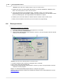
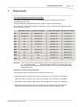
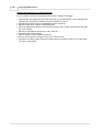
Programming Procedure
7
11
Experiments
Use of the experiment push buttons and LEDs:
The K8048 is equipped with a max. of 4 test inputs that can be operated manually with
SW1,SW2,SW3 and SW4.
The device also has 6 diagnostics LEDs that enable the user to simulate outputs.
Click on the link "cross-reference table" to determine for every IC socket which I/O line is linked to
which push button or LED.
8 pin PIC socket
14 pin PIC socket
18 pin PIC socket
28 pin PIC socket
LD1
GP2 (pin 5)
RC0 (pin 10)
RB0 (pin 6)
RA0 (pin 2)
LD2
GP4 (pin 3)
RC1 (pin 9)
RB1 (pin 7)
RA1 (pin 3)
LD3
NC
RC2 (pin 8)
RB2 (pin 8)
RA2 (pin 4)
LD4
NC
RC3 (pin 7)
RB3 (pin 9)
RA3 (pin 5)
LD5
NC
RC4 (pin 6)
RB4 (pin 10)
RA4 (pin 6)
LD6
NC
NC
RB5 (pin 11)
RA5 (pin 7)
SW1
GP5 (pin 2)
RC5 (pin 5)
RA0 (pin 17)
RB0 (pin 21)
SW2
NC
RA2 (pin 11)
RA1 (pin 18)
RB1 (pin 22)
SW3
NC
NC
RA2 (pin 1)
RB2 (pin 23)
SW4
NC
NC
RA3 (pin 2)
RB4 (pin 25)
Remarks: The I/O lines coming from a pushbutton have to be configured as inputs in the source
(a 1 in the TRIS-register
for that particular entrance). The I/O lines connected
with a LED must be configured as exits in the sources (a 0 in the TRIS-register for that
particular entrance).
Selecting an oscillator with the jumpers
These jumpers allow you to select which IC socket crystal X1 uses.
· Place the shunts in locations JP1 & JP2 for use with the 14-pin socket (e.g. PIC16F630).
· Place the shunts in locations JP3 & JP4 for use with the 18-pin socket (e.g. PIC16F627).
· Place the shunts in locations JP5 & JP6 for use with the 28-pin socket (e.g. PIC16F87x).
· No selection can be made for the 8-pin socket since you would lose two I/O's. With this
particular experiment board you can only use the internal oscillator with this socket.
K8048 © 2003 Velleman Components