1
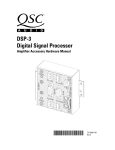
*PROTOTYPE* This unit is for testing/demonstration purposes only. Use with caution. Unit must be returned to QSC upon completion of testing. This unit is a prototype and is not for sale. This unit has not been fully tested or qualified. DSP-3 Digital Signal Processor Amplifier Accessory Hardware Manual TD-000087-00 TD-000087-00 Rev.2 APPLICATION NOTES: •Full feature set, Direct-mounting, No external power or special interconnect cables required. The DSP-3 is fully compatible with the following QSC Audio Products power amplifiers: CX series: DCA series: PL2 series: PL2A series: CX302 DCA1222 PL218 All CX302V DCA1622 PL224 CX502 DCA2422 PL230 CX602V DCA3022 PL236 CX702 DCA3422 CX902 CX1102 CX1202V •Remote Mounting Required, DSP Remote Mount Cable required: Full feature-set, no external power required. The DSP-3 will need to be remotely mounted (accessory remote mount available) and connected to the amplifier’s DataPort with a DSP Remote Mount cable (like a VGA cable but pin #9 is provided) when used with the following amplifiers: CX series: DCA series: CX204V DCA1644 CX254 DCA1824 CX404 •Remote Mounting, DSP Remote Mount Cable and External Power required: Full feature-set. Powerlight series: PL1.0 PL2.0HV PL1.0HV PL2.4MB PL1.4 PL3.4 PL1.5X PL4.0 PL1.6HVX PL6.0* PL1.8 PL9.0* * Powerlight 6.0 and 9.0 MUST have pin #9 removed from the DataPort Cable before use! •Reduced Feature-set, Remote Mounting and External Power required, No DataPort Connection possible: MX series: USA series: PLX series: RMX series non-QSC Amplifiers: All All All All All © Copyright 2000, QSC Audio Products, Inc. QSC® is a registered trademark of QSC Audio Products, Inc., Costa Mesa, CA “QSC” and the QSC logo are registered with the U.S. Patent and Trademark Office “Phoenix Contact” is the trademark of Phoenix Contact, Inc., Middletown, PA “Riacon” is the trademark of RIA electronic, Inc., Eatontown, NJ “On-Shore Technology” is the trademark of On-Shore Technology, Inc., Tempe, AZ All other trademarks are the property of their respective owners 2 TABLE OF CONTENTS Application information by amplifier model.................................................................................................2 Explanation of Graphical Symbols and FCC Statement...........................................................................................4 Section 1: INTRODUCTION Overview......................................................................................................5 Basic Connector & Indicator Descriptions.............................................6 Illustration of DSP-3...................................................................................7 List of Functions and Features..................................................................8 Block Diagram..........................................................................................10 Technical Overview..................................................................................11 . Section 2: INSTALLATION Unpacking..................................................................................................12 What is Included.......................................................................................12 Mounting to QSC DataPort Equipped Amplifiers..................................12 Mounting to the Accessory Remote Mounting Bracket......................13 Connecting Audio Inputs and Outputs...................................................14 Connecting to the DataPort of the DSP-3..............................................15 Connecting to RS-232 Port........................................................................15 Connecting to non-QSC Amplifiers........................................................15 Daisy-chaining the DSP-3 Outputs.........................................................16 Connection to Accessory External DC Power Supply.........................16 Software Installation Instructions and BETA Release Warning........17 Section 4: SPECIFICATIONS.........................................................................................................................................18 Section 5: ARCHITECT’S & ENGINEER’S SPECIFICATION.....................................................................................20 Section 6: APPENDIX DataPort Pinout.........................................................................................21 RS-232 Pinout ............................................................................................22 Terminal Block Connector Part Number Reference.............................22 Section 7: QSC INFORMATION How to Contact QSC Audio Products.....................................................23 3 EXPLANATION OF GRAPHICAL SYMBOLS The lightning flash with arrowhead symbol, within an equilateral triangle, is intended to alert the user to the presence of uninsulated “dangerous voltage” within the product’s enclosure that may be of sufficient magnitude to constitute a risk of electric shock to humans. The exclamation point within an equilateral triangle is intended to alert the users to the presence of important operating and maintenance (servicing) instructions in the literature accompanying the product. EXPLICATION DES SYMBOLES GRAPHIQUES Le symbole éclair avec point de flèche à l’intrérieur d’un triangle équilatéral est utilisé pour alerter l’utilisateur de la presence à l’intérieur du coffret de “voltage dangereux” non isolé d’ampleur suffisante pour constituer un risque d’elétrocution. Le point d’exclamation à l’intérieur d’un triangle équilatéral est employé pour alerter les utilisateurs de la présence d’instructions importantes pour le fonctionnement et l’entretien (service) dans le livret d’instruction accompagnant l’appareil. ERKLÄRUNG DER GRAPHISCHEN SYMBOLE Der Blitz nach unten zeigendem Pfeil in einem gleichseitigen Dreieck weist den Benutzer auf das Vorhandensein einer unisolierten, gefährlichen Spannung“ ” im Gehäuse hin, die stark sein kann, einer Person einen elektrischen Schlag zu versetzen. Das Ausrufzeichen in einem gleichseitigen Dreieck weist den Benutzer auf wichtige Betriebs- und Wartungs- vorschriften in den beiliegenden Unterlagen des Gerätes hin. CAUTION RISK OF ELECTRIC SHOCK DO NOT OPEN CAUTION: To reduce the risk of electric shock, do not remove the cover. No user-serviceable parts inside. Refer servicing to qualified service personnel. WARNING: To prevent fire or electric shock, do not expose this equipment to rain or moisture. AVIS RISQUE DE CHOC ÉLECTRIQUE NE PAS OUVRIR ATTENTION: Pour eviter les risques de choc électrique, ne pas enlever le courvercle. Aucun entretien de pièces intérieures par l’usager. Confier l’entretien au personnel qualifié. AVIS: Pour eviter les risques d’incendie ou d’électrocution, n’exposez pas cet article à la pluie ou a l’humidité. VORSICHT GEFAHR EINES ELEKTRISCHEN SCHLAGES. NICHT ÖFFNEN! VORSICHT: Um das Risiko eines elektrischen Schlages zu vermindern, Abdeckung nicht entfernen! Keine Benutzer Wartungsteile im Innern. Wartung nur durch qualifiertes Wartungspersonal. WARNUNG: Zur vermeidung von Feuer oder elektrischen Schlägen, das Gerät nicht mit Regen oder Feuchtigkeit in Berührung bringen! SAFEGUARDS Electrical energy can perform many useful functions. This unit has been engineered and manufactured to assure your personal safety. Improper use can result in potential electrical shock or fire hazards. In order not to defeat the safeguards, observe the following instructions for its installation, use and servicing. PRECAUTIONS L’énergie électrique peut remplir de nombreuses fonctions utiles. Cet appariel a été conçu et réalisé pour assurer une sécurité personnelle entiére. Une utilisation impropre peut entraîner des risques d’électrocution ou d’incendie. Dans le but de ne pas rendre inutiles les mesures de sécurité, bien observer les instructions suivantes pour l’installation, l’utilisation et l’entretien de l’appareil. 4 Federal Communications Commission (FCC) Information NOTE: This equipment has been tested and found to comply with the limits for a Class B digital device, pursuant to Part 15 of the FCC Rules. These limits are designed to provide reasonable protection against harmful interference in a commercial installation. This equipment generates, uses, and can radiate radio frequency energy and, if not installed and used in accordance with the instructions, may cause harmful interference to radio communications. Operation of this equipment in a residential area is likely to cause harmful interference, in which case the user will be required to correct the interference at his or her own expense. Section 1: Introduction- Overview The DSP-3 is a digital signal processor (or DSP ) accessory for Connections include two D-sub type connections; a DB-9 audio power amplifiers designed to reduce the need for exter- connector acts as the RS-232 interface and an HD-15 through- nal signal processing while increasing overall system reliability connector provides the DataPort interface to a CM16a Amplifier through distributed intelligence. It is intended primarily for Network Monitor (if used). The amplifier-side of the DSP-3 has QSC’s CX, DCA, and Powerlight2 series amplifiers and mounts the other end of the HD-15 through-connector that mates to the directly to the rear panel of the 2-RU models of these amplifiers. DataPort on the rear panel of the amplifier. The “exposed” side Use of the DSP-3 with Powerlight models requires remote has two input connectors and two post-DSP outputs; these are mounting, external power supply and use of a special intercon- 3-pin detachable terminal block connectors (also known as nect cable. Refer to page 2 for application information. The “Euro” or “Phoenix” style connectors). There is also a 2.5mm DSP-3 can also be used with amplifiers that do not have a QSC barrel-type (coaxial) power receptacle for using the DSP-3 with DataPort ( older QSC models, non-QSC models) with a reduced older QSC amplifiers and non-QSC amplifiers. There are two feature set and “remote” mounting/external power. LED’s, a blue one to indicate power status and a green one to The signal processing capabilities include an Input Com- indicate the presence of an input signal to the DSP-3. pressor, multiple Parametric Filters, High- and Low-Pass Filters, Control of the DSP-3 is accomplished with the supplied a Shelf Filter, Muting, Attenuation, Multiple Delays, Polarity stand-alone software. Please refer to the software documenta- Reversal, Audio Routing and Post Crossover Audio Mixing. tion for feature-set and operation information. This software Analog to digital and digital to analog converters are 24 bit provides an easy-to-use graphical user interface where DSP resolution, 48 kHz. sampling rate. Additionally, the post-DSP “objects” are drag-and-drop placed onto a palette and intercon- output signals are daisy-chainable for connection to a second nects are drawn. This interface allows for almost infinite amplifier. Input sensitivity is selectable and dynamic range is configuration possibilities for the end user. Connection of the greater than 95 dB. Inputs and the post-DSP outputs are DSP-3 to the host computer is accomplished by either RS-232 electronically balanced. See page 8 for complete listing. computer port connection or by QSC’s CM16a Amplifier Net- Physically, the DSP-3 is a small module that “piggybacks” work Monitor. Once the DSP-3 has been setup as desired, onto the back panel of the specified QSC amplifiers. It connects connection to the host is no longer required. This feature allows directly to the DataPort on the back panel and is secured with essentially tamper-proof amplifier DSP setup. Further changes supplied hardware. When used with other amplifiers, the DSP- can be implemented in the field by simply connecting a host (i.e. 3 is mounted remotely on a rack-mount accessory that provides laptop computer) and loading the new setup into the DSP. a solid physical mounting platform. Password protection is standard. Note: Powerlight 6.0 and Powerlight 9.0 amplifiers require that pin #9 be removed from the remote mounting interconnect cable. Amplifier damage may result from use of cable that has pin #9 connections present. Normal VGA computer monitor cables have pin #9 removed and are usable. Check before use! 5 Section 1: Introduction- Basic Connector & Indicator Descriptions Below are listed the connector and indicator callouts as they appear on the DSP-3. The bold type indicates the actual labeling on the DSP-3. A brief description of each is provided. “Front”-side connectors & indicatorsCH 1 INPUT- This 3-pin terminal-block jack is where you connect the audio line level input to the DSP-3’s channel #1 input block. It is an electronically balanced input with an input impedance of 7.5k Ohm (7,500 Ohms). When used in an unbalanced configuration, the input impedance is 3.7k Ohms (3,700 Ohms). CH 2 INPUT- Same description as CH1 INPUT, but assigned to the DSP-3’s channel #2 input block. CH 1 OUTPUT- This 3-pin terminal-block jack provides post-DSP (processed) signal from the DSP-3 for daisy-chaining the processed signal to a second amplifier. If using one amplifier only, this output can be unused or used as a monitor source. In the case of non-DataPort amplifiers, this is the DSP-3 output that gets connected to your amplifier’s input connector. Signal source is the DSP-3’s channel #1 output block. CH2 OUTPUT- Same as description as CH 2 OUTPUT only the signal source is the DSP-3’s channel #2 output block. Keep in mind that cross-routing is possible with the DSP-3. This means that the signal input as CH 1 can be routed to CH 2 output (and vice versa). DATA PORT- This HD-15 female jack is where you would connect the CM16a Amplifier Network Monitor (if used). The CM16a allows fullfeatured amplifier monitoring (output power and load impedance measurements, internal amplifier temperature monitoring and much more). Additionally, zone paging and other control features are provided. RS-232- This DB-9 female jack is where the interconnecting serial cable to the host computer is plugged in. EXTERNAL POWER- This jack is utilized when the DSP-3 is used with QSC Powerlight, MX, USA, PLX, RMX, or non-QSC amplifiers. External power is not required for all other directly-mounted-to-amplifier situations. We recommend the use of the QSC external power supply as it has been fully tested with the DSP-3 to assure trouble-free operation. The power requirements for this jack are 15 Volts DC, 300 milliAmperes (mA), with the center of the plug being POSITIVE (+) and the outside being NEGATIVE (-). The size of the plug is: 2.5mm (0.100 inch) ID, 5.5mm (0.218 inch) OD and a length of 9.5mm (0.375 inch). POWER indicator- This blue LED illuminates when the DSP-3 has power properly applied to it. SIGNAL indicator- This green LED illuminates when the DSP-3 detects an input signal on either channel. “Back”-side connectorDataPort jack- This unlabeled HD-15 male jack is where amplifiers with a DataPort are connected to the DSP-3. When used in applications where the DSP-3 is mounted directly to the amplifier, this jack plugs directly into the female jack on the rear of the amplifier, requiring no cable. When used in applications with QSC amplifiers where “remote” mounting is required, this is where you would make the amplifier to DSP-3 cable connection. When used with non-DataPort equipped QSC amplifiers or non-QSC amplifiers, this connection is unused and the feature set of the DSP-3 is reduced. When connecting to Powerlight 6.0 & 9.0 amplifiers, pin #9 must not be present on the interconnecting cable between the DSP-3 and Powerlight 6.0 or 9.0 or amplifier damage may result! 6 Section 1: Introduction- Physical Layout Illustration DSP-3 Overall view DSP-3 front panel (exposed side) DSP-3 rear panel (amplifier side) 7 Section 1: Introduction- List of Functions & Features DSP-3 Hardware Features (full set available to QSC DataPort equipped amplifiers): High- and Low-Pass Crossover Filters Selectable responses: Butterworth (6,12,18 or 24 dB per octave slope) Bessel (6,12,18 or 24 dB per octave slope) Linkwitz-Riley (12 or 24 dB per octave slope) Graphical response curve provided in software Apply Filter (filter in or out) Adjustable frequency & slope Ability to bypass all EQ with a single command Ability to add or delete EQ Assignable anywhere in signal chain High- and Low-Pass Shelf Filter Adjustable corner frequency Adjustable Q factor Adjustable gain Graphical response curve provided in software Apply filter (filter in or out) Ability to bypass all EQ with a single command Ability to add or delete EQ Assignable anywhere in signal chain Output Peak Limiter Adjustable threshold Adjustable attack time Adjustable release time Graphical response curve provided in software Ability to quickly bypass limiter Apply limiter (limiter on or off) Assignable anywhere in signal chain Multiple Delays 910 millisecond maximum, 20.83 microsecond increments, Entry can be in seconds, feet or meters Assignable anywhere in signal chain. 8 Section 1: Introduction- List of Functions & Features Parametric EQ Adjustable frequency Adjustable gain Adjustable Q factor Ability to bypass all EQ with a single command Ability to add or delete EQ Assignable anywhere in the signal chain Apply EQ (EQ in or out) Signal Compressor Adjustable attack and release times Adjustable threshold Adjustable compression ratio Graphical response curve provided in software Assignable anywhere in the signal chain Apply compressor (compressor in or out) Signal Level Meter Peak or rms response Signal Attenuation (mute or bypass) Mix Post Crossover Audio (2 to 1 mixer with mute and lock all channels featured) Signal Splitter External Contact Closure Sensing (for triggering software “events”) Pink & White Noise Generator Variable Frequency Tone Generator Clip & Protect Indication at Amplifier Outputs Signal Polarity Reversal 9 Section 1: Introduction- Block Diagram 10 Section 1: Introduction- Technical Overview This portion of the introduction provides some of the technical details of the DSP-3. Audio Input Path There are two audio channels each with two input connectors, a balanced 3-pin ‘euro’ terminal block jack and a pseudo balanced DataPort input. The inputs are protected with a filter that prevents radio frequency interference. Each input has a selectable input sensitivity of 10dBV, +4dBu, +12dBu, or +18dBu to properly scale the input signal to the CODEC inputs. The DataPort is scaled to clip with a signal that is +10dB compared to the ‘euro’ input. Each CODEC input is diode protected to prevent any large signal from destroying its inputs. Audio Output Path The first stage the audio passes through after the CODEC is an inverting gain stage that takes advantage of the op amp’s CMRR. The second stage of the output is a second order Butterworth low pass filter that removes high frequency sampling artifacts. The signal is then sent out of the DSP-3 through the DataPort or the output ‘euro’ connectors. The output level is selectable from 0dB or -6dB. Power Supply No external power supply is needed for use with the CX, DCA and PL2 series amplifiers (or more recent QSC amplifier models released after printing of this manual). With these models, the DSP-3 is supplied power from the amplifier via the DataPort (HD-15) connection. When used with the Powerlight series of amplifiers, the DSP-3 requires use of the external supply. The external supply is also used when connecting to non-QSC amplifiers (or any amplifier that does not have a DataPort). External power is provided by the included power supply (“wall wart”) via a coaxial power cord jack on the back of the DSP-3. When using the external power source, we recommend that the DSP-3 be powered-up before the amplifier in order to insure trouble-free start-up. This will also avoid the possibility of “thumps & bumps” should the DSP-3 be powered up after the amplifier. Data Acquisition The DSP-3 samples the IMON and VMON lines of QSC amplifiers (via the DataPort) in order to perform dynamics (limiter, compressor, etc.) processing. The four inputs (IMON and VMON for both channels) are continuously sampled by a four channel ADC. When used with non-QSC amplifiers or QSC amplifiers that have no DataPort, dynamics processing is not available. This is because there are no Imon and Vmon lines for the DSP-3 to sample in the absence of a DataPort connection. Contact Closure One contact closure input is provided. It uses pin 9 of the RS-232 DB-9 connector (not normally used for RS-232). Shorting this pin to ground with a maximum impedance of 1.3 kOhms will cause a general purpose I/O pin of the DSP to be pulled to a logic low. This provides the user with an event that can be used in software for many purposes. 11 Section 2: Installation- Basics and Mounting UNPACKING There are no special unpacking precautions for the DSP-3. However, it is recommended that you keep the original packing material for reuse in the rare event that service be required for your DSP-3. If service is required and the original packing material is not available, insure that the DSP-3 is adequately protected for shipment (strong box of appropriate size , sufficient packing material). WHAT IS INCLUDED IN THE CARTON: Item Description Quantity 1- DSP-3 Digital Signal Processor 1 2- 3-pin terminal block connector plug 4 3- #4-40 machine screw, 1.125” long 2 4- #8-32 machine screw, 0.312” long 1 5- Hardware Manual (this document) 1 DIRECT MOUNTING THE DSP-3 TO 2-CH, 2-RU QSC DATAPORT EQUIPPED AMPLIFIERS (CX, DCA, Powerlight2) The DSP-3 mounts directly to the rear of 2-channel, 2-RU, DataPort equipped QSC amplifiers. 1- Configure the amplifiers DIP switches (QSC amplifiers where the DSP-3 covers the configuration switches) as follows: •All filters off •Clip limiter off •Mode set as required 2- Align the DataPort plug on the back of the DSP-3 with the DataPort jack on the back of the amplifier and gently push the DSP-3 to seat the connector. 3- Install the two #4-40 screws to secure the left side of the DSP-3 to the amplifier. These two long screws pass through the DSP-3 and thread into the inserts on the DataPort (HD15) jack. (see below). 4- Install the one #8-32 screw to secure the right side (as view from the rear) of the DSP-3 to the amplifier (see below). 12 Section 2: Installation- Remote mounting (4-ch., Powerlight & non QSC amp’s) REMOTE MOUNTING THE DSP-3 : 4-Channel CX and DCA , Powerlight series, and all non-QSC amplifiers Use of the DSP-3 with the 4-channel CX and DCA and all Powerlight amplifiers requires the remote mounting of the DSP-3. Use with nonQSC amplifiers also requires remote mounting. Keep in mind that all applications that use amplifiers that do not have a DataPort ( i.e. nonQSC amplifiers) the dynamic processing capabilities of the DSP-3 will not be available. Accessory Remote Mounting Bracket- This accessory is a 19”, 2-RU panel with mounting facilities for up to 4 DSP-3 modules. 1- The accessory external mounting bracket kit comes with one large bracket ( the 19”, 2-RU size) and four smaller right-angle brackets that are used for securely mounting up to four DSP-3’s in a 2-RU space. Adjustable rack ears are included for maximum mounting flexibility. 2- Attach the right-angle brackets to the DSP-3 module. The right-angle bracket is attached as shown, below. 3- Attach the DSP-3 & bracket to the main 19” bracket as shown, below. 4- Mount the main bracket assembly in your equipment rack. 5- Attach the input, output, DataPort, RS-232 and external power as required. 13 Section 2: Installation- Connections CONNECTING AUDIO INPUTS AND OUTPUTS: Whenever possible, use balanced connections for the lowest possible noise levels and for minimizing the possibility of hum inducing ground loops. The audio inputs and outputs of the DSP-3 use 3-pin “Phoenix”-type (Euro-style) terminal block connectors. These connectors allow pre-wiring of inputs without any soldering and allow for rerouting of audio inputs by simply interchanging connector locations without the need for any tools. See Appendix for connector manufacturer’s part number reference. To connect your signal wire to the terminal-block plug simply back the screws out a few turns to open the wire-clamp, carefully insert the conductors into the proper location, and re-tighten the clamping screw. The recommended stripping length for the wires is approximately 6 to 8 mm ( 1/4 to 5/16 inch). When stripping the audio cable, be careful not to nick or cut the conductor strands. After each conductor has been stripped and dressed, insert it fully into the connector and tighten the retaining screw. When stranded wire is used, carefully twist the conductor strands together so that when they are inserted into the connector assembly, no loose strands short adjacent terminals. Balanced connection is recommended for all inputs. The terminal block inputs on the DSP-3 are electronically balanced. Balanced input cables are recommended to minimize noise pick up and prevent ground loops. With the connector oriented as shown at the right, connect the positive (+) signal wire to the left-most Unbalanced inputs can be used if required. If unbalanced audio sources are used, it is preferable to use an appropriate audio transformer (or other unbalanced-to-balanced “converter”) to provide a balanced input to the DSP-3. If this is not possible, then it is recommended that the negative terminal and shield terminal be connected to one another with a jumper wire. When using a CM16a Amplifier Network Monitor with the DSP-3, the input signal for channel 1 &2 are provided by the DATA PORT connection. The CH 1 INPUT and CH 2 INPUT connectors should not be used when the DSP-3 is connected to a CM16a Amplifier Network Monitor. 14 Section 2: Installation- Connections CONNECTING TO THE DATAPORT- This section applies to those users interfacing with the QSC CM16a Amplifier Network Monitor and those users interfacing the DSP-3 to a PL6.0 or PL9.0 amplifier. This connection is made with a special 15-pin cable similar to VGA computer monitor cables. Do not use VGA cables as they are not supplied with pin #9 (exception PL6.0 and PL9.0 MUST use VGA type cable or the special cable with pin #9 removed). The plugs and jacks are the same physical size as the RS-232 connections; be careful not to get them confused. The DataPort connection from the DSP-3 to QSC amplifiers is made when mounting the DSP-3 to the rear of the amplifier. The DataPort connection from any other accessory to the DSP-3 is made by orienting the connector properly, inserting it fully into the jack and finger-tightening the retaining screws. The DataPort connection to the DSP-3 is a pass-thru type of connection. The DataPort on the amplifier is used for the connection of the DSP-3 and other QSC DataPort Connection: 15-pin Cable products. Once the DSP-3 has been mounted, the DataPort connector on the DSP-3 passes all the required signals through to the amplifier. Simply plug into the DataPort on the DSP-3 as you would any DataPort on an amplifier. This connection is typically used for connection to an Amplifier Network Monitor such as QSC’s CM16a. The CM16a provides for Ethernet control & monitoring of your amplifiers. Front panel DataPort connection is not required for the operation of the DSP-3. CONNECTING TO THE RS-232 PORT Connection to the RS-232 port is made using a null-modem type 9-pin serial data cable. Just orient the DB-9 plug correctly, insert the plug fully into the RS-232 port and finger-tighten the retaining screws. All DSP-3 setup and programming takes place through the RS-232 port. Any time setup changes are required to the DSP-3, it must be connected to its host computer through the RS-232 port. If “real-time” control of the DSP-3 is required, the RS-232 port connection must be maintained as well. If “real-time” control is not required, then the DSP-3 can be setup first and then disconnected from the PC. The RS-232 connection does not have to be maintained for the DSP-3 to operate. RS-232 Connection: 9-pin Cable 15 Section 2: Installation- Connections DAISY-CHAINING THE DSP-3 OUTPUTS TO ADDITIONAL AMPLIFIERS The DSP-3 provides audio output jacks for each channel. These outputs may be used for daisy-chaining the post-DSP signal to other amplifiers or for monitoring purposes. The signal on the output jacks is post-DSP. All signal processing functions done by the DSP-3 effect the signal provided to the output connectors as well. To daisy-chain the DSP output, simply connect the output jacks of the DSP-3 to the input jacks of the next amplifier. Make sure that all interconnecting cables are balanced and connected properly. CONNECTION TO ACCESSORY EXTERNAL DC POWER SOURCE When the DSP-3 is used with QSC Powerlight amplifiers that do not provide the required +15VDC through their DataPort connection OR is used with non-DataPort amplifiers, power must be supplied to the DSP-3 from an external power supply. QSC offers an accessory external power supply for applications where a DataPort that provides +15 VDC is not available. Contact QSC’s Technical Services Department for details. Although not recommended, third-party external power supplies may work with the DSP-3 provided they are of the correct voltage, voltage type (DC) , current rating and polarity. Any damage to the DSP-3 caused by connection to a non-QSC external power supply is not covered under the warranty. QSC offers an accessory external power supply for applications with non-QSC amplifiers or with QSC Powerlight models that do not provide the required operating voltage. Insert the coaxial power plug into the EXTERNAL POWER jack. Use the “tab” provided on the chassis for securing Ensure that the plug is firmly seated in the jack. the power cord with a tie-wrap (wire-tie). Ensure that any external power supply connected to the DSP-3 is of the proper voltage type, level and current rating. Be certain that the connector polarity is correct as there is no industry standard! Connection to an improper voltage source can cause immediate damage to the DSP-3! 16 Section 2: Installation- Software Installation & BETA Release Warning These instruction apply to the June, 2000 BETA release of the Signal Manager application. Software Installation1. Insert the CD labeled QSC DSP-3 Signal Manager into your CD drive (typically drive “D:”). 2. Run D:\Setup.exe and follow the instructions displayed. 3. When the installation is complete, you will be presented with a screen that asks you to view the “Readme” file. Please take time to read this- it contains important information on how to use the software. 4. After installation, you should have an icon on your desk top labeled “Signal Manager”. Use this icon to start the application. 5. Using the main menu bar at the top of the window, choose the “Help” item and read the Introduction section. 6. IMPORTANT NOTE! The DSP-3 is shipped with all of its pre-sets configured to pass full-range audio signals through both channels, unless the external contact closure is in the closed position (in which case the output of the DSP-3 is muted). THIS MAY NOT BE APPROPRIATE FOR YOUR SETUP! BE sure to configure any necessary crossovers , filters, etc. prior to applying audio signals to the inputs. Damage to equipment may result if these recommendations are not followed. 7. Please refer to the “Readme.txt” file for information on how to provide your feedback on this BETA release product to QSC Audio Products. OVERALL NOTES AND WARNING- • The BETA RELEASE software supplied with the DSP-3 has not been fully qualified to use in a “show” setting. • Use caution when making changes to parameters in a “live” configuration. There are some known problems with undesirable transients when changing filter parameters (especially at low frequencies). • Certain DSP-object configurations have been observed to cause the DSP-3 to perform an auto-reset. This will result in muting of the audio and subsequent re-loading of the power-on-default configuration. It is HIGHLY RECOMMENDED that you establish a power-on-default “preset” that corresponds to your particular equipment setup (such as appropriate crossover filters, gain settings, input sensitivities ect.). Do this as soon as possible so as to reduce the risk of equipment damage that could result should an inappropriate DSP configuration be applied. See the release notes in the software’s “Readme.txt” file for more details. 17 Section 3: Specifications Input Signal Processing Frequency response 20 Hz–10 kHz ±0.3 dB 20 Hz–20 kHz ±0.7 dB Distortion <0.01% THD+N @ +4 dBu out Dynamic range >95 dB unweighted 20 Hz–20 kHz Polarity In-phase or inverted Mute >90 dB attenuation Inputs Program inputs Connector type 2 “Phoenix-style” (a.k.a. “Euro-style”) detachable terminal blocks Type Grounding Electronically balanced All shield terminals connected to chassis Input sensitivity -10dBV, +4dBu, +12dBu, +18dBu selectable Impedance 7.5 K Ohm balanced 4.2 K Ohm unbalanced Common-mode rejection Typical, >50 dB, 20 Hz–20 kHz Worst Case, >40 dB at 20 kHz rolling off to >40 dB at 20 kHz Crosstalk (interchannel within Data Port pair) >75 dB separation, 20 Hz–20 kHz Outputs Program outputs Connector type Pinout Cable type Qualified length 2 (via HD-15) HD-15 DataPort connection Special, see appendix VGA monitor cable 2 meters Daisy-chain output Connector 2 (1 per channel) “Phoenix-style” (a.k.a. “Euro-style”) detachable terminal blocks Type Grounding Electronically balanced Shield terminal connected to chassis Output level Output impedance 0dB, -6dB selectable 600 Ohms balanced Power amplifier connectivity Power amplifier interface Compatibility all QSC and non- QSC amplifiers Full-feature set all QSC DataPort equipped amplifiers Connector and cable HD-15 VGA cable, 2 meters length qualified (for longer runs, contact QSC’s Technical Services Department) RS-232 Port Cable Type Null-Modem (a.k.a. Laplink) Contact closure input (sense) Inputs 1 discrete input Configuration Single-ended input Resistance for closure detect <1.3 K Ohms Resistance for open detect >5 K Ohms 18 Amplifiers one 2-Ch. amplifier per DSP-3 Amplifier status monitor Clip indicator Senses channel clipping Protect indicator Senses amplifier protect status Section 3: Specifications General Physical Height Width Depth 3.50 inches 3.75 inches 1.38 inches Weight Mounting 0.59 lbs (0.27 kg) Rear support recommended for portable or mobile use Operating temperature 0 to 50° Celsius AC Power (applicable for external power supply) AC Input Voltage 80–240 VAC AC Input Current 0,3 Amps rms Frequency 50 to 60 Hz Output Voltage 15 VDC Output Termination Detachable power cord with 2.5mm barrel-type (coaxial) connector center pin is positive Dimensions 19 SECTION 4: ARCHITECT’S AND ENGINEER’S SPECIFICATIONS The Digital Signal Processor (DSP) shall provide two independent channels of DSP for signal delivery to QSC DataPort equipped power amplifiers. The processing shall be distributed with the DSP module mounted directly to the rear of the power amplifiers. Output Peak Limiter—For each audio channel, the DSP shall provide a peak limiter that is assignable anywhere in the signal chain and can be switched on or off. The limiter shall Compressor-- The DSP shall provide a signal compressor that is assignable anywhere in the signal chain. It shall have adjustable threshold, attack time, release time, and compression ratio. Contact Closure I/O—The DSP shall provide a trigger output usable for contact-closure (or other) purpose which shall be CMOS & TTL signal compatible. provide the following adjustments: Power Supply—The DSP shall be provided power through its Gain Threshold Attack time DataPort connection to QSC amplifiers. For older amplifiers or non-QSC amplifiers, a coaxial power jack will be provided on the DSP for connection to an external power source. Power required shall be +15 VDC at 300 mA Release time (max.). High- and Low-Pass Crossover Filters—For each channel of Amplifier Interface—The DSP shall attach directly to the rear of audio, the DSP will provide high-pass and low-pass each power amplifier. The DSP’s interface to each power crossover filters that are assignable anywhere in the amplifier Data Port shall be via an HD-15 connector. This audio chain. The crossover filters must be capable of interface shall transmit two amplifier input audio signals being switched in or out of the signal chain. The DSP as well as all control and monitoring signals. Special shall provide the following crossover responses: signal conditioning and grounding techniques shall be Butterworth (6,12,18,24 dB per octave slope) Bessel (6,12,18,24 dB per octave slope) Linkwitz-Riley (12 & 24 dB per octave slope) used in this interface to ensure negligible levels of noise and crosstalk. Amplifier Output Monitoring—When used with QSC DataPort amplifiers, the DSP shall provide clipping and protect status detection at the amplifier’s output terminals. High- and Low-Pass Shelf Filters—For each audio channel, Noise & Tone Generation-- The DSP shall provide pink and white the DSP shall provide high-pass and low-pass shelf noise generation capability. It shall also provide for tone filters that are assignable anywhere in the audio chain. generation. The shelf filters must be capable of being switched in or out of the signal chain. The DSP shall provide the following shelf filter adjustments: Variable corner frequency Variable gain Variable slope 20 General—All audio inputs and outputs shall be balanced with a nominal input level of +4 dBu and maximum level of +21 dBu. Input connectors shall be of the “Phoenix” detachable terminal block type. The Digital Signal Processor shall be the QSC DSP-3. Section 5: Appendix- DataPort Pinout DATA PORT PINOUT The diagram below shows the pin assignments used for the HD-15 connectors on the DSP-3 and amplifier. NOTE! This information is shown for reference only and is subject to change without notice as the DataPort feature is specific to QSC products and not intended for interface to other manufacturer’s equipment. Pin Signal Description 1 Audio to channel 1 (+) 2 Standby control 3 VMON channel 1 plus encode 1 4 IMON channel 1 plus encode 2 5 Clip/protect channel 1 6 Hard ground 7 Audio to channel 1 (ground) 8 Audio to channel 2 (ground) 9 +15V from amplifier 10 Data reference ground 11 Audio to channel 2 (+) 12 Amp IDR (model ID) 13 VMON channel 2 plus encode 3 14 IMON channel 2 plus encode 4 15 Clip/protect channel 2 Note: Powerlight 6.0 and Powerlight 9.0 amplifiers Description of Encode Signals require that pin #9 be removed from the remote mounting interconnect cable. encode 1 Bridge mode & power detect encode 2 Temperature, channel 1 encode 3 encode 4 Standby mode detect Temperature, channel 2 Amplifier damage may result from use of cable that has pin #9 connections present. Normal VGA computer monitor cables have pin #9 removed and are usable. Check before use! 21 Section 5: Appendix- RS-232 Port Pin-out & Connector P-N’s RS-232 PINOUT: The diagram below shows the pin assignments for RS-232. Pin 1 2 3 4 5 6 7 8 9 Signal Description DCD RD TD DTR Signal GND DSR RTS CTS contact closure TERMINAL BLOCK CONNECTOR PART NUMBER REFERENCE- The following manufacturers and part numbers are provided as a reference to users. The information here is subject to change without the knowledge of QSC. 3 pin without integral strain relief: Phoenix Contact - 17 57 02 2; Riacon - 31249103-6; On Shore Tech - EDZ950/3 Strain Relief 3 pin: Phoenix Contact 17 76 16 8 22 Section 6: How to Contact QSC Audio Products ADDRESS: QSC Audio Products, Inc. 1675 MacArthur Boulevard Costa Mesa, CA 92626-1468 USA TELEPHONE NUMBERS: Main Number (714) 754-6175 Sales Direct Line (714) 957-7100 Sales & Marketing (800) 854-4079 toll free in U.S.A. only Technical Services (714) 957-7150 (800) 772-2834 toll free in U.S.A. only FACSIMILE (FAX) NUMBERS: Sales & Marketing FAX (714) 754-6174 Technical Services FAX (714) 754-6173 WORLD WIDE WEB: http://www.qscaudio.com 23 1675 MacArthur Boulevard Costa Mesa, California 92626 USA PH: (714) 754-6175 FAX: (714) 754-6174 “QSC” and the QSC logo are registered with the U.S. Patent and Trademark Office