1
ZENO®-3200
USER MANUAL
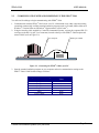
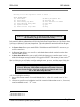
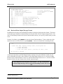
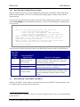
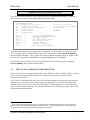
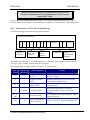
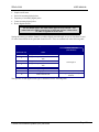
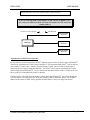
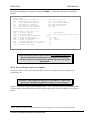
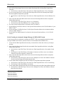
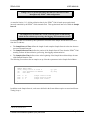
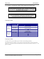
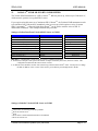
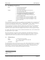
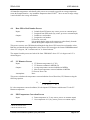
13.5.3. Revision A and Revision D, ZENO®-3200 Communication Wiring Setups
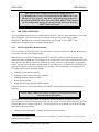
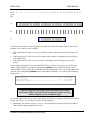
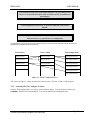
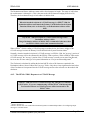
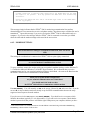
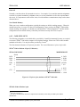
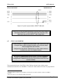
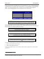
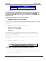
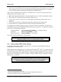
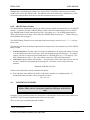
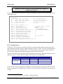
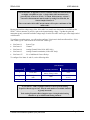
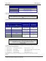
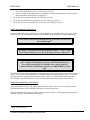
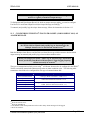
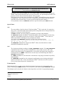
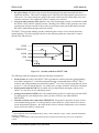
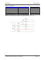
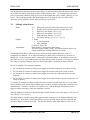
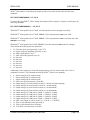
The three COM ports on a Revision A ZENO®-3200 share a common carrier
detect (DCD) line. This single DCD must be asserted before any COM port
on the ZENO®-3200 will respond.
The three COM ports on a Revision D ZENO®-3200 have independent
carrier detect (DCD) lines. Each COM port's DCD must be asserted
correctly before the ZENO®-3200 will respond on that port.
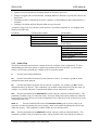
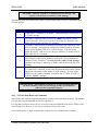
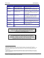
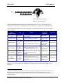
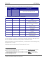
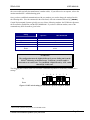
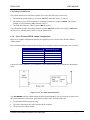
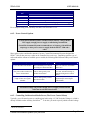
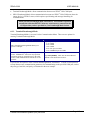
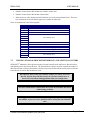
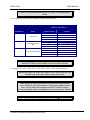
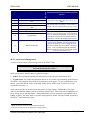
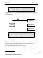
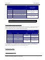
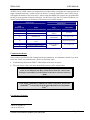
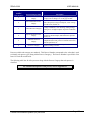
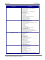
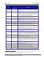
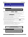
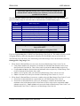
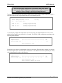
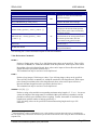
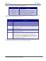
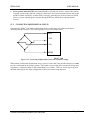
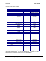
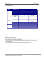
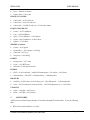
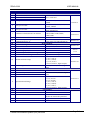
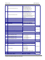
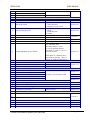
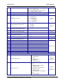
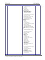
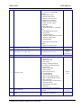
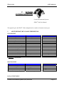
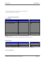
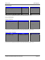
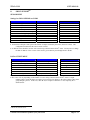
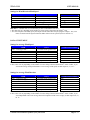
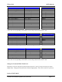
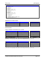
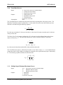
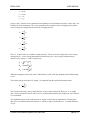
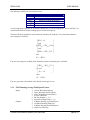
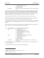
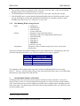
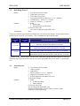
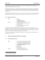
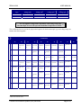
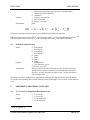
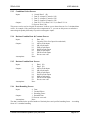
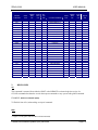
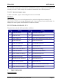
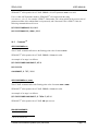
Connecting To COM1
COM1 Port
Type
Lines Required
Receive Data
RS232,
RS232H
RADIO, TWRADIO
Transmit Data
DCD
Ground
Receive Audio
Transmit Audio
Push-To-Talk (PTT)
DCD
Ground
Where to Connect
Rev A ZENO®-3200
Rev D ZENO®-3200
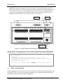
SERIAL DATA, POWER AND GROUNDS terminal strip, pin
labeled COM1 RXD
SERIAL DATA, POWER AND GROUNDS terminal strip, pin
labeled COM1 TXD
AUX Serial Port Pin 8
AUX Serial Port Pin 11
SERIAL DATA, POWER AND GROUNDS terminal strip, any
pin labeled GND
AUX Serial Port Pin 10
AUX Serial Port Pin 9
AUX Serial Port Pin 11
AUX Serial Port Pin 4
AUX Serial Port Pin 8
AUX Serial Port Pin 11
AUX Serial Port Pin 7
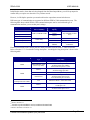
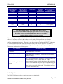
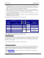
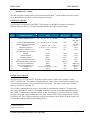
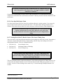
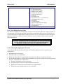
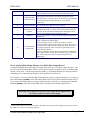
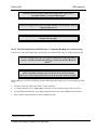
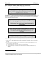
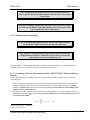
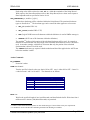
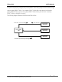
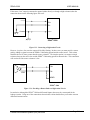
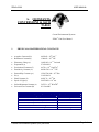
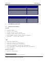
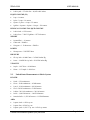
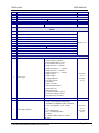
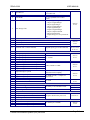
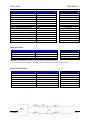
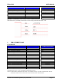
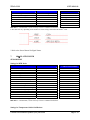
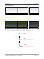
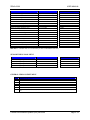
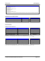
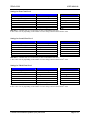
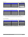
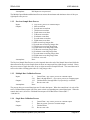
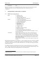
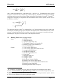
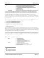
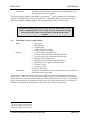
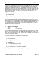
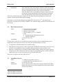
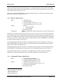
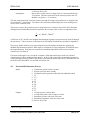
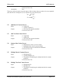
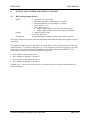
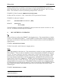
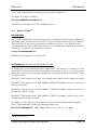
Connecting To COM2
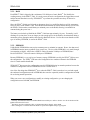
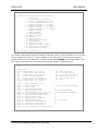
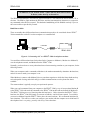
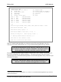
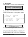
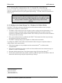
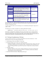
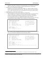
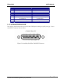
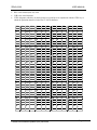
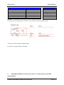
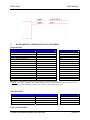
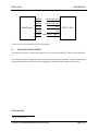
To connect a TTL sensor to COM2, use pins 17 and 18 on the Auxiliary Serial Port.
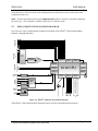
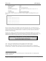
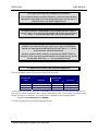
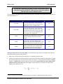
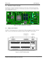
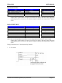
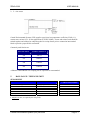
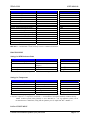
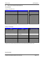
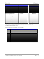
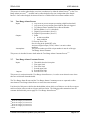
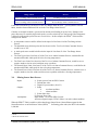
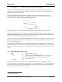
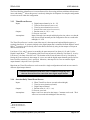
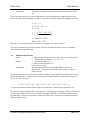
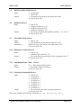
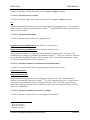
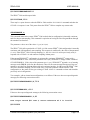
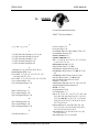
The Compass Port (part of COM2) is a 4-pin connector located on the ZENO®-3200 CPU board and is
labeled as J3. It is located on the lower left-hand corner of the CPU board as shown in Section 13.4. The
pins are as follows:
Coastal Environmental Systems (206) 682-6048
Page 249