1
Q-SERIES
®
QFOT1310 Series
Broadcast Transmitter User Manual
Although every effort has been taken to ensure the accuracy of this document it may be necessary, without notice, to make amendments or correct omissions.
Specifications subject to change without notice.
Q-Series® is a registered trademark of ATX in the United States and/or other countries. Products or features contained herein may be covered by one or more U.S. or foreign
patents. Other non-ATX product and company names in this manual are the property of their respective companies.
TABLE OF CONTENTS
Page
1. PREFACE................................................................................................................................................... 1-1
2. OVERVIEW................................................................................................................................................. 2-1
3. FEATURES................................................................................................................................................. 3-1
4. FUNCTIONAL DIAGRAM........................................................................................................................... 4-1
5.
SPECIFICATIONS...................................................................................................................................... 5-1
5.1. Link Test Condition............................................................................................................................. 5-1
5.2. Specifications Table............................................................................................................................ 5-1
5.3. Optical Link C/N Table........................................................................................................................ 5-2
6.
FUNCTION GUIDE..................................................................................................................................... 6-1
6.1. Front Panel Guide.............................................................................................................................. 6-1
6.2. Rear Panel Guide............................................................................................................................... 6-1
6.3. Parameter Display.............................................................................................................................. 6-2
6.4. Alarm Indication.................................................................................................................................. 6-2
7.
INSTALLATION & ADJUSTMENT............................................................................................................. 7-1
7.1. Opening the Cover............................................................................................................................. 7-1
7.2. Supplies & Tools................................................................................................................................. 7-1
7.3. Installation.......................................................................................................................................... 7-1
8. CLEANING & MAINTENANCE.................................................................................................................. 8-1
9. AFTER-SALE CUSTOMER SERVICE....................................................................................................... 9-1
10. TROUBLESHOOTING.............................................................................................................................. 10-1
11. SERVICE & SUPPORT............................................................................................................................. 11-1
11.1.Contact ATX Networks...................................................................................................................... 11-1
11.2.Warranty Information........................................................................................................................ 11-1
i
This page left intentionally blank.
ii
CHAPTER 1: PREFACE
PREFACE
1.
Preface
This manual is designed for QFOT1310 series 1310nm broadcast transmitter along with a detailed description of product
features, specifications, installation, adjustments and troubleshooting. To install this transmitter successfully and use it safely,
users must read the manual carefully before installation, and perform their installation and adjustments according to this
manual. Otherwise, some practices may lead to property damage or personal injury. Please contact ATX Networks if you
have any questions.
Important User Information
•
Caution: There are invisible laser beams from Fiber output ports, which may cause permanent injury to skin or
eyes.
•
Grounding first before turning on the power (grounding resistance should be less than 4Ω), so as to prevent laser
and user from static damaging.
•
UPS power supply and air conditioned environment are highly recommended for the stable and long-time transmitter
operation.
Q-Series® – QFOT1310 Series Broadcast Transmitter User Manual
1-1
CHAPTER 1: PREFACE
This page left intentionally blank.
Q-Series® – QFOT1310 Series Broadcast Transmitter User Manual
1-2
CHAPTER 2: OVERVIEW
OVERVIEW
2.
Overview
QFOT1310 is a 1310nm DFB laser transmitter delivering TV signals, digital TV signals, telephone voice signals and data
signals over long distance fiber cable for CATV networks. The product utilizes a high performance cooled DFB laser as the
light source, RF power digital automatic process technique, along with RF pre-distortion circuit. At the same time, a built-in
microprocessor monitoring system automatically ensures the excellent performance of this transmitter.
Q-Series® – QFOT1310 Series Broadcast Transmitter User Manual
2-1
CHAPTER 2: OVERVIEW
This page left intentionally blank.
Q-Series® – QFOT1310 Series Broadcast Transmitter User Manual
2-2
CHAPTER 3: FEATURES
FEATURES
3.
Features
•
High performance DFB laser with narrow spectrum and good linearity.
•
RF power digital automatic processing technology.
•
Excellent pre-distortion technology leading to the improved CTB, CSO and C/N.
•
Built-in microprocessor controlling laser and RF performance.
•
Front panel VFD screen displaying the transmitter status.
Q-Series® – QFOT1310 Series Broadcast Transmitter User Manual
3-1
CHAPTER 3: FEATURES
This page left intentionally blank.
Q-Series® – QFOT1310 Series Broadcast Transmitter User Manual
3-2
CHAPTER 4: FUNCTIONAL DIAGRAM
FUNCTIONAL DIAGRAM
4.
Functional Diagram
PREAMPLIFIER
POWER
AMPLIFIER
-20 dB
TEST POINT
DIGITAL
ATTENUATOR
RF INPUT
PRE-DISTORTION
BOARD
AGC/MGC
NETWORK
MANAGEMENT
RF TEST
MICROPROCESSOR
Q-Series® – QFOT1310 Series Broadcast Transmitter User Manual
ATC AUTOMATIC
CONTROL
CIRCUIT
VFD DISPLAY
DFB LASER
OPTICAL
OUTPUT
APC AUTOMATIC
CONTROL
CIRCUIT
POWER SUPPLY
POWER
INPUT
4-1
CHAPTER 4: FUNCTIONAL DIAGRAM
This page left intentionally blank.
Q-Series® – QFOT1310 Series Broadcast Transmitter User Manual
4-2
CHAPTER 5: SPECIFICATIONS
SPECIFICATIONS
5.
Specifications
5.1.
Link Test Condition
Test Condition:
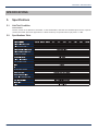
Test link consists of the QFOT1310 transmitter, 10 Km standard fiber, attenuator and standard optical receiver. Input RF
channels are 59 PAL-D channels (equivalent to 77 NTSC channels). The optical receiver input power is -1 dBm.
5.2.
Specifications Table
Q-Series® – QFOT1310 Series Broadcast Transmitter User Manual
5-1
CHAPTER 5: SPECIFICATIONS
5.3.
Optical Link C/N Table
OPTICAL LINK PATH C/N SPECIFICATIONS
OPTICAL LOSS (dB)
QFOT1310-04
QFOT1310-06
QFOT1310-08
QFOT1310-10
QFOT1310-12
QFOT1310-14
QFOT1310-16
QFOT1310-18
QFOT1310-20
QFOT1310-22
4
53.8
5
52.8
6
51.8
7
51.0
53.0
Q-Series® – QFOT1310 Series Broadcast Transmitter User Manual
8
50.1
52.0
52.8
9
49.2
51.0
51.9
52.9
10
48.2
50.1
51.0
51.9
52.7
11
12
49.1
50.1
51.0
51.8
52.4
48.1
49.1
50.1
50.8
51.5
52.0
52.5
13
14
15
16
17
18
48.2
49.1
49.9
50.5
51.0
51.6
51.9
52.2
48.2
49.0
49.5
50.1
50.6
51.0
51.4
48.0
48.6
49.1
49.7
50.0
50.4
47.8
48.1
48.7
49.0
49.4
47.9
48.0
48.6
47.8
5-2
CHAPTER 6: FUNCTION GUIDE
FUNCTION GUIDE
6.
Function Guide
6.1.
Front Panel Guide
1
2
3
4
5
6
7
Front View
1
2
3
4
5
6
7
6.2.
ATX Trademark
LED Status Indicator: Green light: normal; Red light: warning. Check VFD message to troubleshoot problem.
VFD Monitor: Displays each status parameter, product model, serial number and other information about this
transmitter.
UP Button: Scroll the VFD display UP, or increase setting value.
Down Button: Scroll the VFD display DOWN, or decrease setting value.
Enter Button: MGC mode select and ENTER button.
NOTE: The default control mode of the FT13XX transmitter is AGC. If the number of TV channels is less than 15,
press the UP or DOWN button until the VFD displays “MOD LEVEL=XX dBmV”, then press the ENTER button to select
MGC mode. After selecting MGC mode, the VFD will display “MOD LEVEL=XXdBmV” and “Please install…”. At this
point the user can change the modulation level in 1 dB increments by pressing the UP or DOWN buttons. Once you
have selected the desired modulation level, press ENTER again to make it effective. At that time the VFD will display
“MOD LEVEL=XX dBmV” and transmitter will shift back to AGC mode. For instance, if user’s ideal Modulating level is 42
dBmV, VFD would display “MOD LEVEL= 42 dBmV” after operations shown above. Please consult an ATX engineer
for help with this feature.
RF Input Test Port: Standard 75Ω style F-style test port for RF signal on-line test. Level tested from this port is 20 dB
lower than the actual RF drive level to the laser.
Rear Panel Guide
8
9
10
11 12 13
14
15 16 17
Rear View
8
RF Input Port: Standard 75Ω American style F port, used for connecting RF signal and the equipment. Level in this input
port must be at the range of 15~25 dBmV. Too high level may damage laser. Optimum input level is 17 dBmV.
*The input level above 17 dBmV may damage Laser. Please consult factory!
9 Optical Signal Output: Optical signal output port, SC/APC, or optional FC/APC connector. There are invisible laser
emissions from Fiber output when laser is active!
*It would be dangerous to point this port toward the human body especially eyes when equipment is
energized!
10 RS-232 Standard Network Management Port (optional): Use for connecting equipment with RS-232 port in network
management server.
11 Network Management Indicator
Q-Series® – QFOT1310 Series Broadcast Transmitter User Manual
6-1
CHAPTER 6: FUNCTION GUIDE
12 RS-485 Standard Network Management Port (optional): Use for connecting equipment with RS-485 port on network
management server.
13 LAN Network Management Port: Use for connecting transmitter with Ethernet-based network management server.
(Contact factory for this option)
14 Power In: AC power connection.
15 Fuse: AC fuse
16 AC Power Switch: Turn ON or turn OFF the power.
17 Case Grounding Nut: Provided for optionally connecting the transmitter to ground.
6.3.
Parameter Display
6.3.1. Turning On Power Display
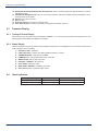
When first turning on the power, the VFD will display “Initialize…” for 2 seconds and the buzzer will briefly tweet one time
indicating that the transmitter has initialized successfully.
6.3.2. Status Display
After the transmitter has been powered ON and initialized, pressing the UP or DOWN button on the front panel will scroll the
VFD to display in turn the following:
1) “Welcome to ATX”: trademark
2) “QFOT1310-xx-SC”: module name, SC indicated output fiber connector
3) “POWER=XX.X mW”: output power, unit mW.
4) “TEMP=XX.X ˚C”: internal temperature value of the laser
5) “BIAS= XX mA”: bias current of the laser
6) “RF INPUT = XXdBmV”: RF input level
7) “ATT= XXdB”: attenuation value
8) “MOD LEVEL= XXdBmV”: modulating level value
9) “S/N: xxxx-xx-xxxx”: equipment series number
6.4.
Alarm Indication
Display Message
Alarm Status
System Indication
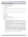
Warning…!!! Input RF is low
Input RF is too low
• Status indicator red light flashes
Warning… !!! Input RF is high
Input RF is too high
• Status indicator red light flashes
Q-Series® – QFOT1310 Series Broadcast Transmitter User Manual
6-2
CHAPTER 7: INSTALLATION & ADJUSTMENT
INSTALLATION & ADJUSTMENT
7.
Installation & Adjustment
7.1.
Opening the Cover
7.1.1. Inspect the package. If the packaging has been damaged, or shows signs of water damage, please contact the freight
company or contact ATX.
7.1.2. After unpacking, check the equipment and accessories according to packing list. If there is any question, please
contact ATX.
7.1.3. If you think equipment has been damaged, please don’t turn on the power and avoid worse damage. Please contact ATX.
7.2.
Supplies & Tools
An optical power meter
A digital multimeter
A Cable TV RF meter or spectrum analyzer
A standard fiber test jumper (FC/APC or SC/APC)
Denatured or 99% pure isopropyl alcohol and lint-free fiber optic cleaning wipes
7.3.
Installation
a). Mount the equipment in the rack and ground the case.
b) Check input voltage using a digital multimeter in accordance with power requirement. Then turn on power.
c) Check the message on the VFD and the status of the front panel LED indicator. Push the UP and DOWN button to
check each parameter, ensuring that the transmitter is operating normally. (If there is no RF input, the red LED will
flash, and the VFD will display “input RF is low”.)
d) Connect standard fiber test cable to the transmitter’s optical signal output. Measure the output optical power and
confirm that the output optical power is the same as the value displayed on the VFD. (When measuring the optical
power, make sure that optical power meter is set for 1310nm wavelength and that fiber test jumper is clean.)
e) Measure the input RF signal level with a Cable TV meter or a spectrum analyzer, making sure that input RF signal
is in the range of 15~25 dBmV (optimum value 17 dBmV). At this time, you can now connect the RF signal to the
RF signal input port of the equipment. This time front panel LED turns to green and VFD displays RF input value as
“RF INPUT = XXdBmV”.
The internal RF power detector is calibrated for 77 analog NTSC channels, so the displayed value may not be correct,
depending upon your actual channel plan. It is possible to correct the displayed value to read your measured RF
level by pressing the UP or DOWN buttons to scroll the VFD until it displays “RF LEVEL=XXdBmV”, and then press
ENTER. The VFD will now display “MOD LEVEL=XXdBmV” and “Please install…”, and the user can now set the
RF input level in 1 dBmV increments by pressing the UP or DOWN buttons. When the displayed value is equal to
your tested value, press ENTER to make it effective, and at that time the VFD will display “RF LEVEL=XXdBmV”.
For instance, if real RF input level is 20 dBmV, VFD would display “RF LEVEL= 20dBmV” after operations shown
above.
f)
Re-measure optical output power, make sure that optical output power being normal, remove standard fiber test
jumper and optical power meter, connect the equipment to network and end the installation.
Q-Series® – QFOT1310 Series Broadcast Transmitter User Manual
7-1
CHAPTER 7: INSTALLATION & ADJUSTMENT
This page left intentionally blank.
Q-Series® – QFOT1310 Series Broadcast Transmitter User Manual
7-2
CHAPTER 8: CLEANING & MAINTENANCE
CLEANING & MAINTENANCE
8.
Cleaning & Maintenance
Each fiber connector can become contaminated by dust or dirt in the operation process, which can result in increased optical
link loss, or a degraded carrier-to-noise ratio. If you find that the optical receiver power or RF output level of the optical
receiver has declined, you should clean and maintain the fiber active connector. The cleaning methods are recommended
below:
a) Carefully unplug or unscrew the active fiber connector from the adapter, while being careful to avoid aiming the fiber
connector at any human body or eye.
b) Use a lint-free fiber optic wipe saturated with alcohol to clean the connector carefully. Once finished, still wait 1-2
minutes until active connector surface is dry in the air.
c) When the cleaned optical active connector is reconnected to the adapter, please do not over-tighten or force the
connector, to avoid damage to the ceramic ferrule.
d) The fiber active connector should be cleaned on both ends. If optical power is still low after cleaning, clean the other
end of the fiber. If the optical power is still low after cleaning both ends, it is recommended that you clean the inner
adaptor. (Take care of the fiber when disassembling the adaptor).
e) Use compressed air or a lint-free wipe to wash the adapter carefully. When using compressed air, aim the nozzle at
the ceramic ferrule of the adaptor to clean.
NOTE:
1. Avoid aiming the optical output or fiber connector at the human body or eyes.
2. Assemble the fiber adaptor gently and carefully to prevent damage to the ceramic ferrule inside the adapter.
Q-Series® – QFOT1310 Series Broadcast Transmitter User Manual
8-1
CHAPTER 8: CLEANING & MAINTENANCE
This page left intentionally blank.
Q-Series® – QFOT1310 Series Broadcast Transmitter User Manual
8-2
CHAPTER 9: AFTER-SALE CUSTOMER SERVICE
AFTER-SALE CUSTOMER SERVICE
9.
After-sale Customer Service
a) Our promises: One year free trouble fixing service and life-long customer service (1 year free guarantee time starts
from the date indicated in products S/N attached on side of products).
b) If the equipment fails, please contact ATX immediately.
c) Don’t try to repair the problem without help from an ATX technician.
d) NOTE: There are adhesive tape seals on both sides of the case. Any unauthorized removal of this tape seal by the
user will void the 1 year warranty.
Q-Series® – QFOT1310 Series Broadcast Transmitter User Manual
9-1
CHAPTER 9: AFTER-SALE CUSTOMER SERVICE
This page left intentionally blank.
Q-Series® – QFOT1310 Series Broadcast Transmitter User Manual
9-2
CHAPTER 10: TROUBLESHOOTING
TROUBLESHOOTING
10. Troubleshooting
SYMPTOM
FAULT
ACTION
No VFD or LED display after
turning on the power.
No input power or a problem with the
internal switching power supply.
Check input AC voltage to the power
supply (AC90V~250V), if the voltage is
normal, usually the cause is the internal
switching power supply, contact ATX.
After turning on power, VFD
monitor and LED normal, but
optical output power low.
1. Check jumper quality.
2. Contaminated optical active connector
or adapter.
3. Damaged ceramic ferrule in adapter.
1. Swap to a good test jumper.
2. Clean contaminated fiber active
connector or adapter.
3. Swap the damaged adapter.
After connecting to network, all
1. Low received optical power, causing
TV channels have obvious noise poor C/N.
point.
2. RF input level too low for sufficient
laser modulation.
3. System link path C/N too low.
4. Back-reflection from bad or dirty
optical connectors.
1. Clean fiber active connector or adapter
(Chapter 8 Cleaning & Maintenance).
2. Check RF input levels to transmitter
(15-25 dBmV).
3. Check link loss.
4. Use only angled (SC/APC) optical
connectors or fusion splice where
necessary.
After connecting to network,
only some TV channels have a
degraded SNR.
Some channels SNR too low.
Check the individual channel signal C/N
or SNR.
Check the flatness of the RF input signal.
After connecting to network,
some TV channels have obvious
ripple, beats, lines, or distortions.
1. Optical input power to receiver too
high.
2. RF modulation too high.
3. RF input drive to transmitter too high.
1. Check input power at optical receiver
and pad if necessary.
2. Check optical transmitter modulation
level parameter, and readjust if too
high.
3. Make sure the RF input level is within
the range (15~25 dBmV).
Addendum note: to reset the transmitter to the default settings, as shipped from the factory, follow the following steps:
1. Power unit OFF.
2. While holding in both the UP and DOWN buttons, power the unit ON.
3. The VFD will display “Test Mode”, and the transmitter will emit a loud beeping noise.
4. Power the unit OFF for 5 seconds, and then back ON. The modulation and display settings have now been restored
to the factory defaults. These settings will work for 99% of the applications, and it is rarely needed to deviate from
these. Please consult the factory if unsure.
Q-Series® – QFOT1310 Series Broadcast Transmitter User Manual
10-1
CHAPTER 10: TROUBLESHOOTING
This page left intentionally blank.
Q-Series® – QFOT1310 Series Broadcast Transmitter User Manual
10-2
CHAPTER 11: SERVICE & SUPPORT
SERVICE & SUPPORT
11. Service & Support
11.1. Contact ATX Networks
Please contact ATX Technical Support for assistance with any ATX products. Please contact ATX Customer Service to obtain
a valid RMA number for any ATX products that require service and are in or out-of-warranty before returning a failed module
to the factory.
ATX Networks
1-501 Clements Road West
Ajax, ON L1S 7H4 Canada
Tel:
(905) 428-6068
Toll Free:
(800) 565-7488
Fax:
(905) 427-1964
Toll Free Fax:
(866) 427-1964
Web: www.atxnetworks.com
E-mail: [email protected]
11.2. Warranty Information
All of ATX Networks’ products have a 1-year warranty that covers manufacturer’s defects or failures.
Q-Series® – QFOT1310 Series Broadcast Transmitter User Manual
11-1
Tel +1 (905) 428-6068
Printed in Canada
1-501 Clements Road West, Ajax, ON L1S 7H4 Canada
Toll Free +1 (800) 565-7488 Fax +1 (905) 427-1964 Toll Free Fax +1 (866) 427-1964
www.atxnetworks.com [email protected]
Rev. 11/10 (ANW0787)