1
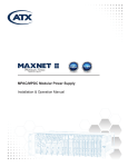
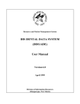
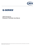
SignalOn® Series
RF Switch Module
Installation & Operation Manual
D3.1 /
CCAP™
Compliant
1.2 GHz
Although every effort has been taken to ensure the accuracy of this document it may be necessary, without notice, to make amendments or correct omissions.
Specifications subject to change without notice.
SignalOn® Series is a registered trademark of ATX in the United States and/or other countries. Products or features contained herein may be covered by one or more U.S. or
foreign patents. Other non-ATX product and company names in this manual are the property of their respective companies.
TABLE OF CONTENTS
Page
Introduction......................................................................................................................................................... iii
Admonishments................................................................................................................................................. iii
General Safety Precautions............................................................................................................................... iii
Certification......................................................................................................................................................... iii
FCC Compliance Statement.............................................................................................................................. iii
1. GENERAL................................................................................................................................................... 1-1
1.1.
Compatibility with RFWorx® Product Line........................................................................................... 1-1
2. PRODUCT DESCRIPTION......................................................................................................................... 2-1
2.1.
RF Switch Module Configurations...................................................................................................... 2-1
2.2.
Features............................................................................................................................................. 2-1
3. APPLICATIONS.......................................................................................................................................... 3-1
4. SPECIFICATIONS...................................................................................................................................... 4-1
5. INSTALLATION.......................................................................................................................................... 5-1
5.1.
Alarm Connections............................................................................................................................. 5-1
6. SYSTEM OPERATION............................................................................................................................... 6-1
6.1.
Input RF Level Calibration.................................................................................................................. 6-3
6.2.
RF Input Level Calculation................................................................................................................. 6-3
6.3.
Protection Switching........................................................................................................................... 6-4
6.4.
Alarm Contact Closure....................................................................................................................... 6-4
7. SERVICE & SUPPORT............................................................................................................................... 7-1
7.1.
Contact ATX Networks........................................................................................................................ 7-1
7.2.
Warranty Information.......................................................................................................................... 7-1
7.3.
Safety................................................................................................................................................. 7-1
S
ignalOn® Series – RF Switch Module – Installation & Operation Manual
i
Index of Figures and Tables
Figures
#1 Single RF Switch Module.......................................................................................1-1
#2 Dual RF Switch Module..........................................................................................1-1
#3 General Application Amplifier Redundancy............................................................3-1
#4 General Application Path Redundancy...................................................................3-1
#5 RF Switch Module Installation 2RU Chassis..........................................................5-1
#6 RF Switch Module Installation 5RU Chassis..........................................................5-2
#7 Single RF Switch Module.......................................................................................6-2
#8 Dual RF Switch Module..........................................................................................6-2
Tables
#1 Physical and Environmental Specifications............................................................4-1
#2 Electrical Specifications..........................................................................................4-1
#3 Rear Panel Connections and Switches..................................................................6-1
#4 Front Panel Indicators and Control.........................................................................6-1
#5 RF Input Level Calculations....................................................................................6-3
#6 Switch Logic............................................................................................................6-4
ii
SignalOn® Series – RF Switch Module – Installation & Operation Manual
PREFACE
Introduction
The SignalOn Series RF Switch Module is designed to be installed in the 8- or 20-position SignalOn Series chassis. Each
RF switch module occupies two positions in the chassis. The mechanical dimensions, cable management, and aesthetics
of the RF Switch Module are compatible with the SignalOn product line. The system is designed to accommodate superior
cable management and ease of use.
Admonishments
Important safety admonishments are used throughout this manual to warn of possible hazards to persons or equipment.
An admonishment identifies a possible hazard and then explains what may happen if the hazard is not avoided. The
admonishments — in the form of Dangers, Warnings, and Cautions — must be followed at all times. These warnings are
flagged by use of the triangular alert icon (seen below), and are listed in descending order of severity of injury or damage
and likelihood of occurrence.
Danger: Danger is used to indicate the presence of a hazard that will cause severe personal injury, death, or substantial
property damage if the hazard is not avoided.
Warning: Warning is used to indicate the presence of a hazard that can cause severe personal injury, death, or substantial
property damage if the hazard is not avoided.
Caution: Caution is used to indicate the presence of a hazard that will or can cause minor personal injury or property
damage if the hazard is not avoided.
General Safety Precautions
Warning: Never install equipment in a wet location or during a lightning storm.
Certification
SignalOn Forward Path products have been tested and found to comply with the requirements of UL 60950, and CSA 22.2
No. 0.7, emissions EN55022 radiated and conducted.
FCC Compliance Statement
The SignalOn Forward Path Amplifier product line has been certified to comply with the requirements for class A computing
devices per part 15 of the FCC regulations.
Warning: This equipment generates, uses, and can radiate radio frequency energy and if not installed and used in accordance
with the instruction manual, may cause interference to radio communications. It has been tested and found to comply with
limits for a Class A digital device pursuant to Subpart B of Part 15 of FCC Rules, which are designed to provide reasonable
protection against such interference when operated in a commercial environment. Operation of this equipment in a residential
area is likely to cause interference to TV and radio reception in which case the user, at their own expense, will be required to
take whatever measures may be required to correct the interference.
This equipment does not exceed Class A limits for radio emission for digital apparatus, set out in the radio interference
regulation of the authorization methods of Industry Canada. Operation in a residential area may cause unacceptable
interference to TV and radio reception requiring the owner or operator to take whatever steps are necessary to correct the
interference.
SignalOn® Series – RF Switch Module – Installation & Operation Manual
iii
PREFACE
This page left intentionally blank.
iv
SignalOn® Series – RF Switch Module – Installation & Operation Manual
CHAPTER 1: GENERAL
GENERAL
1.General
The SignalOn system is a modular system that permits high isolation combining, splitting, switching, and amplification of
headend signals in a CATV system. The system is designed to accommodate strong cable management, EMI shielding, and
ease of use. This facilitates easy reconfiguration and high performance within a dynamic headend environment.
The SignalOn RF Switch Module (RFSM) is designed for use with the SignalOn 8-position, or 20-position powered chassis.
All RF connections to the switch are made through standard 75 Ohm BNC, or F connectors located on the rear. All operating
controls and indicators are located on the switch front panel with configuration controls located on the rear.
Each SignalOn RF Switch Module (RFSM) occupies two positions in a chassis. Up to nine RFSMs and one power supply,
or eight RFSMs and two load-sharing, redundant power supplies can be installed in a vertical 20-position (5RU) SignalOn
chassis. Ten RFSMs may be installed in the vertical 20-position SignalOn chassis if an external +24 VDC power source
is used.
Each RFSM or power supply occupies two positions in a chassis. Up to three RFSMs and one power supply, or two RFSMs
and two load-sharing, redundant power supplies can be installed in a horizontal 8-position (2RU) SignalOn chassis. Four
RFSMs may be installed in the horizontal 8-position SignalOn chassis if an external +24 VDC power source is used.
Switch modules are shown in Figure 1 and Figure 2.
Figure #1: Single RF Switch Module
1.1.
Figure #2: Dual RF Switch Module
Compatibility with RFWorx® Product Line
SignalOn switch modules, amplifiers and power supplies may be installed in the same chassis as the SignalOn Passive
modules. They are not physically compatible with the earlier RFWorx® chassis.
SignalOn® Series – RF Switch Module – Installation & Operation Manual
1-1
CHAPTER 1: GENERAL
This page left intentionally blank.
1-2
SignalOn® Series – RF Switch Module – Installation & Operation Manual
CHAPTER 2: PRODUCT DESCRIPTION
PRODUCT DESCRIPTION
2.
Product Description
Primary function of the module is to monitor the RF signal gain on the operating primary “A” input, and switch to the backup
“B” input if the gain of the primary path rises, or falls below the calibrated RF input level of the unit. If the “A” input side goes
above, or falls below the threshold of the unit, the RFSM quickly switches the input from the failed input to the secondary
input. Switching occurs in less than 10 milliseconds. Switch status, failure LEDs, and RF level bar graphs are located on the
front panel of the switch module.
2.1.
RF Switch Module Configurations
• Single Circuit Redundant RF Switch Module - BNC Connector
• Single Circuit Redundant RF Switch Module - F Connector
• Dual Circuit Redundant RF Switch Module - BNC Connector
• Dual Circuit Redundant RF Switch Module - F Connector
2.2.Features
• Continuous monitoring of primary and secondary paths
• Wide power detector range: >50 dBm
• Detects both high and low power failures
• User-selectable switching threshold: ±3 dB or ±6 dB
• Fail-over switching time <10ms
• Front-panel LED status and dual power level displays
• Alarm contact for remote failure monitoring
• Available in BNC and F-Connector configurations
• Single, or Dual modules
• Easily configured for redundancy or A-B switch applications
• Front panel bar graph display provides indication of RF power and switching threshold
• Indication of switch status provided by front panel LED and rear terminal block contacts
• Easily configured switching threshold levels via rear DIP switch
• One-step calibration
• Auto switch-back feature to primary input
• Built-in delay to prevent from false switching
• Automatic or Manual modes of operation
• Latching relays in signal path preserves service in case of power failure
SignalOn® Series – RF Switch Module – Installation & Operation Manual
2-1
CHAPTER 2: PRODUCT DESCRIPTION
This page left intentionally blank.
2-2
SignalOn® Series – RF Switch Module – Installation & Operation Manual
CHAPTER 3: APPLICATIONS
APPLICATIONS
3.Applications
Typical applications of this switch are to protect two optical to RF receivers, or redundant amplifiers. In this setup, the RFSM
can independently protect one or two pairs of receivers, or amplifiers. Once the RFSM detects a signal level rising above, or
falling below the preset threshold level, it switches from A to B or B to A for that RFSM. Status conditions for all switches are
available locally through the front panel controls.
The RFSM in the Figure 3 and Figure 4 may be user configured to suit different applications, two methods are shown. A
customer may elect to use two ports from a passive combiner module to supply identical signals to redundant amplifiers A
and B. The RFSM would then monitor each amplifier output signal and switch to the other amplifier as necessary for 1:1
redundancy.
The RFSM can also be configured as a conventional A-B switch, where a main input is passed, and a different back-up signal
may be automatically or manually switched to.
Either configuration of RF switching reverts back to the RF-A signal path once it has been restored, after a short hold-off time
of 15 seconds. This is referred to as Auto Switchback. Either input (A or B) may be selected manually to facilitate system
maintenance, or left to run in AUTO mode as a redundant switch or RF selector.
Each RFSM is designed with latching relays. If power to a module fails, relay contacts retain the selected path and the
calibration data is stored.
MICROWAVE
BASEBAND
DOWN
MODULATOR
CONVERTER VIDEO/AUDIO
BASEBAND
DOWN
MODULATOR
CONVERTER VIDEO/AUDIO
BASEBAND
SATELLITE
VCR VIDEO/AUDIO
COMBINER/
SPLITTER
RFSM
AMP
B
MODULATOR
OFF-AIR SIGNALS
OPTICAL
TRANSMITTER
AMP
A
AMP
TO
CABLE
PLANT
AMP
Figure #3: General Application Amplifier Redundancy
PRIMARY
PATH
RF IN A
RFSM
RF OUT
SECONDARY
PATH
RF IN B
Figure #4: General Application Path Redundancy
SignalOn® Series – RF Switch Module – Installation & Operation Manual
3-1
CHAPTER 3: APPLICATIONS
This page left intentionally blank.
3-2
SignalOn® Series – RF Switch Module – Installation & Operation Manual
CHAPTER 4: SPECIFICATIONS
SPECIFICATIONS
4.
Specifications
Specifications are noted in Table 1, and Table 2.
PARAMETER
SPECIFICATIONS
REMARKS
Physical
Dimensions (W × D × H)
1.7 × 5.9 × 8.5 inches (4.3 ×14.9 × 21.6 cm)
Weight
Single
Dual
1.54 pounds (0.7 kg)
1.86 pounds (0.8 kg)
Environmental
Operating Temperature
0°C to +50°C (+32°F to +122°F)
Storage Temperature
–40°C to +70°C (–40°F to +158°F)
Storage Humidity
20 to 90%
No condensation
Table #1: Physical and Environmental Specifications
Table #2: RF Switch Specifications
SignalOn® Series – RF Switch Module – Installation & Operation Manual
4-1
CHAPTER 4: SPECIFICATIONS
This page left intentionally blank.
4-2
SignalOn® Series – RF Switch Module – Installation & Operation Manual
CHAPTER 5: INSTALLATION
INSTALLATION
5.Installation
Each RF switch module occupies two slots in the chassis. Use the following procedure to install modules in the SignalOn
Series chassis.
1. Make sure the ATX logo (or any other front panel lettering) is readable. Align the power connector at the top of the
module with the power connector in the chassis. Slide the plugin module into its designated location in the chassis.
Warning: Never install equipment in a wet location or during a lightning storm.
2. Secure the module using its two captive retaining screws. See Figure 5 or Figure 6.
3.After each module is loaded into the chassis, refer to your work order, and connect the designated RF cables to the
appropriate BNC or F connectors on the modules in the chassis.
4.Carefully route cables through the cable management slots located on each side of the rear of the chassis. Use the
cable management guidelines found in this manual to route cable from the chassis to the rack/cabinet.
5. Perform any cabling or operational tests required at your facility.
5.1.
Alarm Connections
Alarm is activated by a relay contact closure when a loss of an input signal occurs or a loss of power at the RFSM. Connect
any pre-existing alarm system to the terminals on the rear of the switch module. Repeat the connection process for the
second switch on the dual switch module.
SINGLE RF
SWITCH
MODULE
POWER CONNECTOR
(FACING CENTER
OF CHASSIS)
Figure #5: RF Switch Module Installation 2RU Chassis
SignalOn® Series – RF Switch Module – Installation & Operation Manual
5-1
CHAPTER 5: INSTALLATION
DUAL RF
SWITCH
MODULE
Figure #6: RF Switch Module Installation 5RU Chassis
5-2
SignalOn® Series – RF Switch Module – Installation & Operation Manual
CHAPTER 6: SYSTEM OPERATION
SYSTEM OPERATION
6.
System Operation
There are four LEDs and two bar graph indicators, one toggle switch, and a SET button on the front panel of the single switch
module. The dual switch module has two sets of indicators and controls on the front panel. Refer to Table 3 for a description
of the rear connectors and DIP switches. Refer to Table 4 for a description of each indicator and switch. Location of the
indicators and switches are shown in Figure 7 and Figure 8.
FUNCTION
DESCRIPTION
Power Connector
Accepts Power from SignalOn Chassis
OUT
RF Output Connection
IN-A
Primary RF Input Connection (A)
IN-B
Back-up RF Input Connection (B)
6 dB / 3 dB (SW 1)
±3 dB or ±6 dB Switching Threshold
LIM OFF/LIM ON (SW 2)
High Limit (+3 dB / +6 dB) Disable
A≠B / A=B (SW 3)
B-Relative-To-A
ALM LOC / ALM UNLOC (SW 4)
Alarm Lock / Unlock
ALM
Relay Contact for External Alarm
Table #3: Rear Panel Connections and Switches
INDICATOR
Status
IN-A
IN-B
A-B Status
COLOR
DESCRIPTION
GREEN
Operating Properly
RED
Power or RFSM Failed
GREEN
RF-Input A is Within Threshold (±3 dB or ±6 dB)
RED
RF-Input A is Out of Threshold Limits
FLASHING GREEN
Manual Mode
GREEN
RF-Input B is Within Threshold (±3 dB or ±6 dB)
RED
RF-Input B is Out of Threshold Limits
FLASHING GREEN
Manual Mode
GREEN
RF-OUT is Switched to A-IN
YELLOW
RF-OUT B is Switched to B-IN
A-AUTO-B (Switch)
Auto
Switched to Automatic Mode
A
A-IN Manually Switched to OUT
B
B-IN Manually Switched to OUT
Bar Graph A
Signal Level Display for RF-Input A
Bar Graph B
Signal Level Display for RF-Input B
Set
Press to Initiate Calibration of RFSM Input Levels
Table #4: Front Panel Indicators and Control
SignalOn® Series – RF Switch Module – Installation & Operation Manual
6-1
CHAPTER 6: SYSTEM OPERATION
Front View
Rear View
Figure #7: Single RF Switch Module
Front View
Rear View
Figure #8: Dual RF Switch Module
6-2
SignalOn® Series – RF Switch Module – Installation & Operation Manual
CHAPTER 6: SYSTEM OPERATION
6.1.
Input RF Level Calibration
Calibration is performed using the SET button. The RFSM compares each RF input level to a user-selected ±3 dB or ±6 dB
switching threshold, and to minimum/maximum input limits. To pass calibration, when B-Relative-To-A Mode is selected, the
power level of B must be within the threshold window of A. The B power level display indicates B’s power level with respect to
the calibrated reference level of Path-A. The minimum/maximum signal levels the RFSM operates at are –28 dBm to 22 dBm
composite input power. Calibration attempts that fail due to signal levels out of the specified range display a red LED on the
appropriate path LED (A or B) and the status LED turns red. To recalibrate the SET button must be held for several seconds.
During calibration several bar graph LEDs may light until just the center two bar graph LEDs light.
During Manual Mode operation, either Path-A or Path-B may be selected. The non-selected path is not monitored and alarm
contacts are closed. The LED & bar graph displays input of the power reference to only the input switches. All calibration
information is maintained and restored once Automatic Mode is again selected.
During Automatic Mode of operation, Path-A is always the primary path, and the RFSM always selects A or switches back to
A if it is in a normal operating state.
The RFSM uses the following path selection criteria during a calibration attempt in automatic switch mode at initial setup as
well as any future resets:
Automatic Mode Examples
ExampleAction
6.2.
A passes / B = don’t care
Select Path-A
A fails / B = don’t care
No change. (Path-A should always pass calibration. If it fails, leave the relay
unchanged).
RF Input Level Calculation
The proper input level to the switch is determined by two criteria, channel loading (number of channels being transported),
and RF reference Level in dBmV of each individual RF carrier. See Table 5. The exact formula for calculation of RF Input
level to the RFSM is as follows;
dBmV (total power) = dBmV/ch + 10log (# ch)
dBm = dBmV –48.75 (assumes 75 Ohm impedance)
Example; 130 channels each running at +30 dBmV
dBmV (total power) = 30+10Log (130)
dBmV (total power) = 30+(10) 2.114
dBmV (total power) = 51.14 dBmV
dBm = dBmV (total power) –48.75 (assumes 75 Ohm impedance)
dBm = 51.14 – 48.75
dBm = 2.39
PER CHANNEL
76 CHANNELS (550 MHz SYSTEM)
130 CHANNELS (870 MHz SYSTEM)
dBmV
dBm
dBmV Total Power
dBm Total Power
dBmV Total Power
dBm Total Power
0
–48.75
18.81
–29.94
21.14
–27.61
10
–38.75
28.81
–19.94
31.14
–17.61
20
–28.75
38.81
–9.94
41.14
–7.61
30
–18.75
48.81
–0.06
51.14
2.39
40
–8.75
58.81
10.06
61.14
12.39
50
1.25
68.81
20.06
71.14
22.39
Table #5: RF Input Level Calculations
SignalOn® Series – RF Switch Module – Installation & Operation Manual
6-3
CHAPTER 6: SYSTEM OPERATION
6.3.
Protection Switching
Upon detecting a path failure, the RFSM switches to the alternate path within 10ms. Table 6 indicates the switching logic of
the RFSM based on input conditions:
RFSM CONFIGURATION
RELAY ACTION
User has Manually Selected Path-A
Never Switched; Always on A
User has Manually Selected Path-B
Never Switched; Always on B
Auto-mode: Path-A Failure, Path-B is OK
Switched to B
Auto-mode: Path- A Failure, Path-B Failed
No Change
Auto-mode: Path-B Failure, Path-A is OK
Switch to A
Auto-mode: Path-B Failure, Path-A Failed
No Change
Auto-mode: RFSM Power Recovery, Path-A is OK, Path-B No Change
Select/Switch to A
Auto-mode: RFSM Power Recovery, Path-A Failed, Path-B is OK
Select/Switch to B
Auto-mode: RFSM Power Recovery, Path-A Failed, Path-B Failed
No Change
Table #6: Switch Logic
6.4.
Alarm Contact Closure
Alarms may be activated by relay contact closure when a loss of an input signal occurs or loss of power at the RFSM. Front
panel LED’s also indicate an alarming condition. During Manual mode, the unselected path is not monitored and the alarm
is on.
The alarm is cleared if the RFSM is in automatic mode and all conditions return to the previously calibrated state. If the alarm
is triggered due to a Path A failure, power at Path A must return to within ±2 dB if set to ±3 dB mode or to within ±4 dB if set
to ±6 dB mode. If Path B triggers the alarm the power level must return to ±3 dB or ±6 dB depending on the mode. Placing
ALM LOC/ALM UNLOC switch (dipswitch 4) in the alarm lock position prevents alarms from being cleared unless the RFSM
is re-calibrated, it recovers from a loss of power, or by pressing SET for one second.
6-4
SignalOn® Series – RF Switch Module – Installation & Operation Manual
CHAPTER 7: SERVICE & SUPPORT
SERVICE & SUPPORT
7.
Service & Support
7.1.
Contact ATX Networks
Please contact ATX Technical Support for assistance with any ATX products. Please contact ATX Customer Service to obtain
a valid RMA number for any ATX products that require service and are in or out-of-warranty before returning a failed module
to the factory.
TECHNICAL SUPPORT
Tel: (905) 428-6068
Toll Free: (800) 565-7488 (USA & Canada only)
► Press *3 for Technical Support
► Then press 1 for Digital Video Products (DVIS, DigiVu, UCrypt, etc.)
► OR, press 2 for All Other Products
Email: [email protected] for Digital Video Products
Email: [email protected] for All Other Products
CUSTOMER SERVICE
ATX Networks
1-501 Clements Road West
Ajax, ON L1S 7H4 Canada
Tel: (905) 428-6068
Toll Free:
(800) 565-7488 (USA & Canada only)
► Press *1 for Customer Service
Fax: (905) 427-1964
Toll Free Fax: (866) 427-1964 (USA & Canada only)
Web: www.atxnetworks.com
Email: [email protected]
7.2.
Warranty Information
All of ATX Networks’ products have a 1-year warranty that covers manufacturer’s defects or failures.
7.3.Safety
IMPORTANT! FOR YOUR PROTECTION, PLEASE READ THE FOLLOWING:
WATER AND MOISTURE: Care should be taken so that objects do not fall and liquids are not spilled into the enclosure
through openings.
POWER SOURCES: The device should be connected to a power supply only of the type described in the operating instructions
or as marked on the device.
GROUNDING OR POLARIZATION: Precautions should be taken so that the grounding or polarization means of the device
is not defeated.
POWER CORD PROTECTION: Power supply cords should be routed so that they are not likely to be pinched by items
placed upon or against them, paying particular attention to cords at plugs, convenience receptacles, and the point where
they exit from the device.
SERVICING: The user should not attempt to service the device beyond that described in the operating instructions. All other
servicing should be referred to qualified service personnel.
FUSING: If your device is equipped with a fused receptacle, replace only with the same type fuse. Refer to replacement text
on the unit for correct fuse type.
SignalOn® Series – RF Switch Module – Installation & Operation Manual
7-1
1-501 Clements Road West, Ajax, ON L1S 7H4 Canada
Tel +1 (905) 428-6068 Toll Free +1 (800) 565-7488
Fax +1 (905) 427-1964 Toll Free Fax +1 (866) 427-1964
www.atxnetworks.com [email protected]
Printed in Canada
Rev. 11/15 (ANW0846)