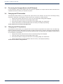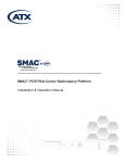
1
HFC
Enhance
®
D3.1 /
CCAP™
Compliant
1.2 GHz
QFHPN High Power Optical Node with AGC
Installation & Operation Manual
Although every effort has been taken to ensure the accuracy of this document it may be necessary, without notice, to make amendments or correct omissions.
Specifications subject to change without notice.
HFC Enhance® is a registered trademark of ATX in the United States and/or other countries. Products or features contained herein may be covered by one or more U.S. or
foreign patents. Other non-ATX product and company names in this manual are the property of their respective companies.
TABLE OF CONTENTS
1. IMPORTANT SAFEGUARDS. . . . . . . . . . . . . . . . . . . . . . . . . . . . . . . . . . . . . . . . . . . . . . 1-1
2. INSTALLATION AND OPERATION. . . . . . . . . . . . . . . . . . . . . . . . . . . . . . . . . . . . . . . . . 2-1
2.1
Installation. . . . . . . . . . . . . . . . . . . . . . . . . . . . . . . . . . . . . . . . . . . . . . . . . . . . . . . . 2-2
2.2
Mounting. . . . . . . . . . . . . . . . . . . . . . . . . . . . . . . . . . . . . . . . . . . . . . . . . . . . . . . . . 2-2
2.3
Grounding. . . . . . . . . . . . . . . . . . . . . . . . . . . . . . . . . . . . . . . . . . . . . . . . . . . . . . . . 2-2
2.4
Connecting COAX . . . . . . . . . . . . . . . . . . . . . . . . . . . . . . . . . . . . . . . . . . . . . . . . . 2-2
2.5
Connecting Optical Fibers . . . . . . . . . . . . . . . . . . . . . . . . . . . . . . . . . . . . . . . . . . . 2-2
3. POWER UP AND TEST . . . . . . . . . . . . . . . . . . . . . . . . . . . . . . . . . . . . . . . . . . . . . . . . . . 3-1
3.1
Connect the Power Adapter. . . . . . . . . . . . . . . . . . . . . . . . . . . . . . . . . . . . . . . . . . 3-1
3.2
Verify Signal Levels . . . . . . . . . . . . . . . . . . . . . . . . . . . . . . . . . . . . . . . . . . . . . . . . 3-1
3.3
Fine-tuning the Compact Node to the RF Network. . . . . . . . . . . . . . . . . . . . . . . . . 3-2
3.4
Changing the RF Attenuation. . . . . . . . . . . . . . . . . . . . . . . . . . . . . . . . . . . . . . . . . 3-2
3.5
Changing the RF Equalization . . . . . . . . . . . . . . . . . . . . . . . . . . . . . . . . . . . . . . . . 3-2
4. SPECIFICATIONS. . . . . . . . . . . . . . . . . . . . . . . . . . . . . . . . . . . . . . . . . . . . . . . . . . . . . . . 4-1
5. SERVICE & SUPPORT. . . . . . . . . . . . . . . . . . . . . . . . . . . . . . . . . . . . . . . . . . . . . . . . . . . 5-1
5.1
Contact ATX Networks. . . . . . . . . . . . . . . . . . . . . . . . . . . . . . . . . . . . . . . . . . . . . . 5-1
5.2
Warranty Information . . . . . . . . . . . . . . . . . . . . . . . . . . . . . . . . . . . . . . . . . . . . . . . 5-1
HFC Enhance® – QFHPN High Power Optical Node with AGC – Installation & Operation Manual
i
This page intentionally left blank
ii
HFC Enhance® – QFHPN High Power Optical Node with AGC – Installation & Operation Manual
CHAPTER 1: IMPORTANT SAFEGUARDS
IMPORTANT SAFEGUARDS
1.
Important Safeguards
ATX Networks strongly advises you to read the following safety instructions prior to installing and operating this equipment.
•
Read These Instructions First – All safety and operating instructions should be read before installing or operating
this equipment.
•
Retain This User Manual – Safety and operating instructions must be retained for future reference.
•
Ventilation – The optical node should be kept at a distance from other objects to keep from overheating. Maximum
operating ambient temperature is 131°F (55°C).
•
Power Sources – The mains circuit should be a dedicated, un-switched supply. Keep the unit away from high voltage
or other interference creating devices such as motors, compressors, etc.
CAUTION: For continued protection against risk of fire, replace circuit breakers/fuses
(if necessary) with one of only the same type and rating.
OPTICAL OUTPUT SAFETY: Optical compact node units may emit harmful invisible laser radiation if powered on and the case is opened or the beam path is exposed.
CAUTION
INVISIBLE LASER RADIATION
DO NOT VIEW DIRECTLY
WITH OPTICAL INSTRUMENT
CLASS 1M LASER PRODUCT
The ATX Networks’ QFHPN compact node is classified as Class 1M per IEC/EN 60825-1/A2:2001. This product complies with
FDA/CDRH, 21 CFR 1040.10 and 1040.11 except for deviations pursuant to Laser Notice No. 50 dated 26 July, 2001.
Viewing the laser output with certain optical instruments (for example, eye loupes, magnifiers and Miniscopes) within a distance
of 100 mm may pose an eye hazard.
Laser power up to 26 mW at 1310 nm could be accessible if optical connector is open or fiber is broken. Lasers are Powered
ON whenever the unit is powered.
CAUTION: Use of controls, adjustments, and procedures other than those specified herein
may result in hazardous laser radiation exposure.
HFC Enhance® – QFHPN High Power Optical Node with AGC – Installation & Operation Manual
1-1
CHAPTER 1: IMPORTANT SAFEGUARDS
This page intentionally left blank
1-2
HFC Enhance® – QFHPN High Power Optical Node with AGC – Installation & Operation Manual
CHAPTER 2: INSTALLATION AND OPERATION
INSTALLATION AND OPERATION
2.
Installation and Operation
15
14
13
12
11
10
9
8
1.
2.
3.
4.
5.
6.
7.
8.
9.
10.
11.
12.
13.
14.
15.
Downstream RF output level test port (-20dB)
Downstream RF output / Upstream RF input
Upstream RF test port (-20dB)
Power input +5~+8VDC
Upstream fiber output
Downstream fiber input
Grounding lug and screw
Mounting screw slot
Control buttons
3-digit Status display
Power ON /alarm LED
Mode LED RF LEVEL power
Mode LED Optical in/out power
Mode LED Attenuation settings
Mode LED Equalization settings (tilt)
7
1
2
3
4
5
6
Figure #1 – QFHPN 2-way Compact Node
1.
2.
3.
4.
5.
6.
7.
8.
9.
10.
11.
12.
13.
Downstream RF output port 1
Downstream RF output port 2
Downstream fiber input
Power input +5~+8VDC
Grounding lug and screw
Mounting screw slot
Control buttons
3-digit Status display
Power ON /alarm LED
Mode LED RF LEVEL
Mode LED Optical in/out power
Mode LED Attenuation settings
Mode LED Equalization settings (tilt)
Figure #2 – QFHPN 1-way Receive Only Compact Node
HFC Enhance® – QFHPN High Power Optical Node with AGC – Installation & Operation Manual
2-1
CHAPTER 2: INSTALLATION AND OPERATION
2.1Installation
The ATX Networks QFHPN compact node is designed to operate in a utility room or closet. It must be placed in a location
where it will not be directly exposed to liquid or to extreme temperatures. Please refer to Figure 1 or Figure 2 above
(depending on model being installed) for installation and operation.
2.2Mounting
The compact node is designed to be mounted directly on a wall or other indoor surface. It should be placed so an operator
can view the status display for installation or troubleshooting. Attach the compact node to a wall board with the connectors
facing downward. Use appropriate mounting hardware (not included) for the surface you are mounting it on. The slots on the
compact node will accommodate screw type fasteners from sizes #8 to #12.
2.3Grounding
The compact node should be grounded to electrical/utility ground using at least #10 solid ground wire. This will minimize the
risk of electrical shock and minimize the effect of noise on the coax cable inside the building. Follow all electrical codes and
standards that apply when installing this equipment.
2.4
Connecting COAX
Connect the building video coax wire to the output of the CATV compact node. For best results the building should use RG6
coax cable or better with as short of runs as possible. The compact node is designed to output 40dBmV of RF power (44
dBmV x2 on QFHPN-D44), and includes the ability to compensate for long distance coax runs if long runs cannot be avoided.
Be sure that all electrical couplers are of the 2-way type, or poor performance will result with cable modems and some set-top
boxes. When attaching the coax cable to the CATV compact node, use appropriate tools – do not over tighten or you may
damage the node. A loose or damaged coax connection may also result in poor signal stability as temperature changes over
time.
2.5
Connecting Optical Fibers
CAUTION: NEVER look into the ends of a fiber optic cable that is connected to the network!!
Communications systems use lasers that emit invisible infrared light, which can do permanent
damage to your eyes.
Other general recommendations:
•
Use only Single Mode Fiber (SMF) optic cable (9/125µM). Multi-Mode Fiber (MMF) is incompatible with the equipment
and will result in unacceptable performance and possible damage to the equipment.
•
All fiber splices should be fusion-type splices. Avoid mechanical or compression type connections.
•
Insure that you follow local practices when working with fiber optic cable as tight bends or excessive pulling on the
fiber jumpers may damage the cable.
•
For optimum performance, fiber runs should be made directly from the transmitter to the receiver. Minimize the use
of adapters, patch panels and additional points of failure and signal loss.
•
In order to ensure return loss is maximized, use only SC/APC connectors. Clean and inspect connectors and fiber
end-faces prior to installation, and every plug in/out cycle.
•
Use only industry approved methods, materials, and solutions for cleaning.
•
Do not turn on the transmitter alone or without a protector cover at the unit connector end, otherwise the laser can do
harm, especially to eyes. This is especially critical because the laser is invisible.
•
Always turn off the laser prior to making connections to the transmitter. Failure to do so may cause irreparable
damage to the laser and transmitter.
Attaching the fibers to the CATV compact node:
2-2
•
Before connecting the optical fiber to the CATV compact node, inspect and clean the optical connector before
connecting the optical network jumper.
•
Insert the forward path fiber into the correct connector and confirm that the cable “snaps” into place.
•
Clean and inspect the upstream return path connector on the compact node and connect the return path fiber jumper.
Confirm that the return path connector “snaps” into place (QFHPN-2W only).
HFC Enhance® – QFHPN High Power Optical Node with AGC – Installation & Operation Manual
CHAPTER 3: POWER UP AND TEST
POWER UP AND TEST
3.
Power Up and Test
The compact node is now ready for power up.
3.1
Connect the Power Adapter
Insert the 5mm power plug from the power converter into the power port of the compact node and plug the adapter into the
120VAC wall outlet.
The compact node will conduct a self-test and the power LED will be flashing. As the test proceeds each of the mode LEDs
are lit in sequence. When the self test is complete, the output power LED is lit, and the display shows the current RF output
power level.
A green power LED indicates that the unit is operating correctly and the RF output is within acceptable limits. (See alarm
indicator section if the SYS/ALARM LED is not showing green).
Secure the low voltage cable from the compact node such that it does not become easily tangled or dislodged.
3.2
Verify Signal Levels
The compact node is equipped with a built in power meter for the RF output and the optical input/outputs. Use the arrow control
keys to select the values you want to view as follows:
3.2.1 Check RF Power Output Level
Use the arrow control buttons to select the RF LEV mode. (When the compact node completes its initial diagnostics, it will
automatically be selected). The display indicates the RF output power, measured in dBmV/Ch. Note that the attenuation
setting will directly affect the output power value for the compact node.
•
Using an RF Signal Meter, confirm the RF downstream power level output. The output level should be approximately
+40dBmV per channel with an optical input of from -8 to +1dBmV.
◦◦ The RF level can also be measured from the RF output test port. The level at the test port will be
approximately 20 dB below the actual RF output level.
3.2.2 Check Optical Power Receive and Optical Output Levels
Use the arrow control buttons to select the OP IN/OUT mode. Both the input and the output optical power levels can be viewed.
Enter the OP IN/OUT mode by pressing the down arrow and the display shows the optical input power from the network. The
value on the display is shown in dBm, and should be between -9 and +1. (The ideal setting is -3)
Pressing the down-arrow button again shows the upstream optical output power level being generated by the compact node,
also measured in dBm. This value should measure between 0 to +2.
•
Using an Optical Power Meter, verify that the downstream (forward path) signal on the fiber cable coming from the
head-end is between -9 and + 1 dBm.
•
Using an Optical Power Meter, verify the upstream output of the compact node (return path) is between 0 and +2dBm
(QFHPN-2W only).
3.2.3 Check the Upstream RF Power Level (QFHPN-2W only)
The compact node has no direct measurement of the upstream RF power it is receiving. You will need to confirm the received
RF power from a cable modem at the head-end, or at the RF test port on the CATV compact node.
•
Using an RF Signal Meter, verify the RF input to the compact node is between+23 dBmV and +35dBmV. The
measurement at RF upstream input test port will be 20 dB below the actual input level.
HFC Enhance® – QFHPN High Power Optical Node with AGC – Installation & Operation Manual
3-1
CHAPTER 3: POWER UP AND TEST
3.3
Fine-tuning the Compact Node to the RF Network
In some cases, the output of the compact node may need to be adjusted. The compact node has built-in attenuation and
equalization features that allow you to optimize the system.
3.4
Changing the RF Attenuation
The attenuation feature allows you to reduce the RF output into the coax network in the case where overdriving is being
experienced. Attenuation can be applied in 1dB increments up to a maximum of 16db as follows:
1. Using the arrow button, select the “ATT” mode. The current attenuation setting will be displayed.
2. Press and hold the return button until the display starts to blink.
3. Use the arrow buttons to change the value shown on the blinking display to a desired value.
4. Click the return button to set the attenuation value into memory. The display stops blinking.
The RF output level has now been changed and set.
3.5
Changing the RF Equalization
The Equalization feature allows you to change the tilt on the RF output to compensate for the losses in the coax cable. High
frequency channels tend to be attenuated by the cable more than the low frequency channels. Changing the tilt attenuates the
lower channels but not the high channels to overcome the cable loss issues. The attenuation can be applied in 1dB increments
up to a maximum of 16 as follows:
1. Using the arrow button, select the “EQ” mode. The current tilt setting will be displayed.
2. Press and hold the return button until the display starts to blink.
3. Use the arrow buttons to change the value shown on the blinking display to a desired value.
4. Click the return button to set the equalization value into memory. The display stops blinking.
The RF tilt has now been changed and set.
3-2
HFC Enhance® – QFHPN High Power Optical Node with AGC – Installation & Operation Manual
CHAPTER 4: SPECIFICATIONS
SPECIFICATIONS
4.
Specifications
HFC Enhance® – QFHPN High Power Optical Node with AGC – Installation & Operation Manual
4-1
CHAPTER 4: SPECIFICATIONS
This page intentionally left blank
4-2
HFC Enhance® – QFHPN High Power Optical Node with AGC – Installation & Operation Manual
CHAPTER 5: SERVICE & SUPPORT
SERVICE & SUPPORT
5.
Service & Support
5.1
Contact ATX Networks
Please contact ATX Technical Support for assistance with any ATX products. Please contact ATX Customer Service to obtain
a valid RMA number for any ATX products that require service and are in or out-of-warranty before returning a failed module
to the factory.
TECHNICAL SUPPORT
Tel:
(905) 428-6068
Toll Free:
(800) 565-7488 (USA & Canada only)
► Press *3 for Technical Support
►Then press 1 for Digital Video Products (DVIS, DigiVu, UCrypt, etc.)
►OR, press 2 for All Other Products
Email: [email protected] for Digital Video Products
Email: [email protected] for All Other Products
CUSTOMER SERVICE
ATX Networks
1-501 Clements Road West
Ajax, ON L1S 7H4 Canada
Tel:
(905) 428-6068
Toll Free:
(800) 565-7488 (USA & Canada only)
► Press *1 for Customer Service
Fax:
(905) 427-1964
Toll Free Fax: (866) 427-1964 (USA & Canada only)
Web:
www.atxnetworks.com
Email:
[email protected]
5.2
Warranty Information
The ATX Networks QFHPN has a one year warranty and is subject to ATX Networks’ standard warrantee terms.
There are no user serviceable components inside the unit. The warranty is void if the unit is opened or is damaged due to
misuse.
HFC Enhance® – QFHPN High Power Optical Node with AGC – Installation & Operation Manual
5-1
1-501 Clements Road West, Ajax, ON L1S 7H4 Canada
Tel +1 (905) 428-6068 Toll Free +1 (800) 565-7488
Fax +1 (905) 427-1964 Toll Free Fax +1 (866) 427-1964
www.atxnetworks.com [email protected]
Printed in Canada
Rev. 11/15 (ANW1004)