1
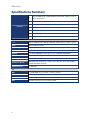
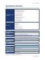
Specification
ENX-LX800
Data Modul AG - www.data-modul.com
ENX-LX800
AMD® Geode LX800 500MHz Nano ITX Main Board
User’s Manual
Ver. 1.00
ENX-LX800
Contents
Safety Information ..........................................................................................................4
Technical Support ............................................................................................................5
Conventions Used in This Guide ....................................................................................5
Packing List .......................................................................................................................6
Revision History ...............................................................................................................7
Specifications Summary..................................................................................................8
Block Diagram.................................................................................................................10
Production Introduction ...............................................................................................12
1.1
Before you Proceed ................................................................................................12
1.2
Motherboard Overview............................................................................................13
1.2.1
Placement Direction ....................................................................................................................... 13
1.2.2
Screw Holes ................................................................................................................................... 13
1.3
Motherboard Layout ................................................................................................14
1.3.1
1.4
Expansion Slots ......................................................................................................17
1.4.1
Installing an Expansion Card ......................................................................................................... 17
1.4.2
Configuring an Expansion Card ..................................................................................................... 17
1.5
Jumpers ..................................................................................................................18
1.5.1
Clear CMOS (J3) ............................................................................................................................ 18
1.5.2
LCD Backlight Brightness Adjustment Connector (LCDPJ1)......................................................... 19
1.5.3
COM1/COM2 RI/+5V Selection (COMAJ1, COMBJ1)................................................................... 19
1.5.4
COM1/COM2 +5V/+12V Selection (COMAPJ1, COMBPJ1) ......................................................... 19
1.6
2
Layout Content List ........................................................................................................................ 15
Connectors..............................................................................................................20
1.6.1
Rear Panel Connectors .................................................................................................................. 20
1.6.2
CF Power Connector (CFPJ1) ....................................................................................................... 21
1.6.3
ATX Power Connector (CN5) ......................................................................................................... 21
1.6.4
Power Fan Connector (CN7).......................................................................................................... 21
1.6.5
SM Bus Connector (CN8)............................................................................................................... 22
1.6.6
Serial port 1 in RS-232 mode (COMB1)......................................................................................... 22
1.6.7
Serial port 2 in RS-232 mode (COMB2)......................................................................................... 22
1.6.8
Front Panel Connector (FPANEL1)................................................................................................ 23
1.6.9
IrDA Connector (IRB1) ................................................................................................................... 24
1.6.10
Primary IDE Connector (IDEB1) ................................................................................................ 24
1.6.11
AC97 Line-in Connector (J1) ..................................................................................................... 25
1.6.12
GPIO Connector (J2) ................................................................................................................. 25
User’s Manual
Contents
1.6.13
LCD Inverter Connector (LCDB1) .............................................................................................. 26
1.6.14
LVDS Connector (LVDS1) ......................................................................................................... 26
1.6.15
TTL Connector (TTL1) ............................................................................................................... 27
1.6.16
USB 2.0 Connector (USBB1)..................................................................................................... 27
ENX-LX800
3
ENX-LX800
Safety Information
Electrical safety
To prevent electrical shock hazard, disconnect the power cable from the electrical
outlet before relocating the system.
When adding or removing devices to or from the system, ensure that the power cables
for the devices are unplugged before the signal cables are connected. If possible,
disconnect all power cables from the existing system before you add a device.
Before connecting or removing signal cables from the motherboard, ensure that all
power cables are unplugged.
Seek professional assistance before using an adapter or extension cord. These
devices could interrupt the grounding circuit.
Make sure that your power supply is set to the correct voltage in your area. If you are
not sure about the voltage of the electrical outlet you are using, contact your local
power company.
If the power supply is broken, do not try to fix it by yourself. Contact a qualified service
technician or your retailer.
Operation safety
Before installing the motherboard and adding devices on it, carefully read all the
manuals that came with the package.
Before using the product, make sure all cables are correctly connected and the power
cables are not damaged. If you detect any damage, contact your dealer immediately.
To avoid short circuits, keep paper clips, screws, and staples away from connectors,
slots, sockets and circuitry.
Avoid dust, humidity, and temperature extremes. Do not place the product in any area
where it may become wet.
Place the product on a stable surface.
If you encounter technical problems with the product, contact a qualified service
technician or your retailer.
The symbol of the crossed out wheeled bin indicates that the product
(electrical and electronic equipment) should not be placed in
municipal waste. Check local regulations for disposal of electronic
products.
4
User’s Manual
Technical Support
If a problem arises with your system and no solution can be obtained from the user’s
manual, please contact your place of purchase or local distributor. Alternatively, please try
the following help resources for further guidance. Visit the Avalue website for FAQ,
technical guide, BIOS updates, driver updates, and other information:
http://www.avalue.com.tw
Conventions Used in This Guide
To make sure that you perform certain tasks properly, take note of the following symbols
used throughout this manual.
DANGER/WARNING: Information to prevent injury to yourself when
trying to complete a task.
CAUTION: Information to prevent damage to the components when
trying to complete a task.
IMPORTANT: Instructions that you MUST follow to complete a task.
NOTE: Tips and additional information to help you complete a task.
ENX-LX800
5
ENX-LX800
Packing List
Before you begin installing your single board, please make sure that the following materials
have been shipped:
1 x AMD LX800 Nano ITX Main board
1 x CD-ROM contains the followings:
- User’s manual (this manual in PDF file)
- Drivers
2 x Serial port cable
1 x 6 to 20 pin power cable
1 x Y cable
1 x IDE HDD cable
1 x Startup Manual
If any of the above items is damaged or missing, please contact your
retailer.
6
User’s Manual
Revision History
Revision
V 1.0
Revision History
First release for PCB 1.00
Date
September 04, 2007
ENX-LX800
7
ENX-LX800
Specifications Summary
1
Features
Onboard AMD Geode LX800 500 MHz @ 0.9 W with 128K L2 Cache &
64K L1 Cache CPU
2
AMD Geode CS5536 Companion Chip
3
One 200-pin SODIMM up to 1GB DDR 400 SDRAM
4
24-bit TTL, 18-bit LVDS
5
Realtek RTL8139DL 10/100Mbps LAN
6
1 Mini PCI, Type I/II CF
7
2 COM, 4 USB 2.0
System
CPU
Onboard AMD Geode LX800 @ 0.9 W with 128K L2 Cache or 64K L1 Cache
BIOS
Award 4 Mb Flash BIOS
System Chipset
AMD Geode LX800/CS5536
I/O Chipset
Winbond W83627HG-AW
Memory
1 x 200-pin SODIMM socket supports up to 1 GB DDR 400 SDRAM
SSD
1 x CompactFlash Type I/II socket
Watchdog Timer
Reset: 1 sec.~255 min. and 1 sec. or 1 min./step
H/W Status Monitor
Expansion Slots
Monitoring CPU temperature, voltage, and cooling fan status. Auto throttling
control when CPU overheats
1 x Mini PCI
I/O
MIO
1 x EIDE (DMA 33), 2 x RS-232, 1 x K/B, 1 x Mouse
IrDA
115k bps, IrDA 1.0 compliant
USB
4 x USB 2.0 ports
DIO
8-bit General Purpose I/O for 4 DI and 4 DO
8
User’s Manual
Specifications Summary
I/O
1 x 6Pin ATX compatible power connector
1x LVDS 20Pin Panel Connector
1x TTL 40Pin Panel Connector
1x Front Panel Connector
Internal I/O
1 x 44Pin IDE Connector
2 x COM Port Connector
1 x LCD Invert Power Connector
1 x 3Pin FAN Connector
1 x ext. USB Connector
1 x ext Line-in Connector
1 x PS/2 Keyboard+Mouse (through Y-Cable)
1 x VGA port
Back Panel
2 x USB 2.0/1.1
1 x RJ45 port
1 x Audio Jack for Mic-in
1 x Audio Jack for Line-out
Display
Display Memory
Resolution
VGA/LCD interface
AMD LX800 integrated graphics controller supports up to 32 MB video memory
CRT mode: 1024 x 768 @ 32 bpp (85 Hz)
TFT mode: 1600 x 1200 @ 32 bpp (100Hz)
AMD Geode LX800 supports 18-bit Single channel LVDS
Audio
Chipset
AMD Geode CS5536
AC97 Codec
Realtek ALC655 supports 2 CH AC97 Audio
Audio Interface
Mic in, Line in, Line out
Ethernet
LAN1
Realtek RTL8139DL 10/100Mbps LAN
Mechanical & Environmental
Power Type
ATX
Operating Temperature
0 ~ 60°C (32 ~ 140°F)
Operating Humidity
0% ~ 90% relative humidity, non-condensing
Size (L x W)
4.72" x 4.72" (120 mm x 120 mm)
Weight
0.88 lbs (0.4 Kg)
* Specifications are subject to change without notice.
ENX-LX800
9
ENX-LX800
Block Diagram
10
User’s Manual
This chapter describes the motherboard
features and the new technologies
it supports.
1
Product
introduction
ENX-LX800
11
ENX-LX800
Production Introduction
1.1 Before you Proceed
Take note of the following precautions before you install motherboard components or
change any motherboard settings.
12
Unplug the power cord from the wall socket before touching any
component.
Use a grounded wrist strap or touch a safely grounded object or a
metal object, such as the power supply case, before handling
components to avoid damaging them due to static electricity
Hold components by the edges to avoid touching the ICs on
them.
Whenever you uninstall any component, place it on a grounded
antistatic pad or in the bag that came with the component.
Before you install or remove any component, ensure that the ATX
power supply is switched off or the power cord is detached from
the power supply. Failure to do so may cause severe damage to
the motherboard, peripherals, and/or components.
User’s Manual
1.2 Motherboard Overview
Before you install the motherboard, study the configuration of your chassis to ensure that
the motherboard fits into it. Refer to the chassis documentation before installing the
motherboard.
Make sure to unplug the power cord before installing or removing the
motherboard. Failure to do so can cause you physical injury and
damage motherboard components.
1.2.1
Placement Direction
When installing the motherboard, make sure that you place it into the chassis in the correct
orientation. The edge with external ports goes to the rear part of the chassis as indicated in
the image below.
1.2.2
Screw Holes
Place four (4) screws into the holes indicated by circles to secure the motherboard to the
chassis.
Do not over tighten the screws! Doing so can damage the
motherboard.
Place this side towards the rear of the
chassis
ENX-LX800
13
ENX-LX800
1.3 Motherboard Layout
14
User’s Manual
1.3.1
Layout Content List
Slots
Label
Function
Note
Page
CF1
CompactFlash card connector
(Rear side)
N/A
SODIMM1
200-pin DDR SDRAM DIMM socket
(Rear side)
N/A
PCI1
Mini PCI slot
N/A
Jumpers
Label
Function
Note
Page
J3
Clear CMOS
3 x 1 header, pitch 2.00mm
18
LCDPJ1
LCD Backlight Brightness
Adjustment Connector
3 x 1 header, pitch 2.54mm
19
COMAJ1
COM 1 RI/+5V selection
3 x 1 header, pitch 2.54mm
19
COMAPJ1
COM 1 +5V/+12V selection
3 x 1 header, pitch 2.54mm
19
COMBJ1
COM 2 RI/+5V selection
3 x 1 header, pitch 2.54mm
19
COMBPJ1
COM 2 +5V/+12V selection
3 x 1 header, pitch 2.54mm
19
Rear Panel Connector
Label
Function
Note
Page
CN1
PS/2 keyboard and mouse
6-pin Mini-Din
20
VGA1
VGA port
D-sub 15-pin, female
20
USB23
USB 2.0 connector x 2
20
CN9
RJ-45 Ethernet connector
20
CN2
Line-in / Line-out port
Phone jack
20
CN3
Microphone port
Phone jack
20
ENX-LX800
15
ENX-LX800
Internal Connector
Label
Function
Note
Page
CFPJ1
CF power connector
3 x 2 header, pitch 2.54mm
21
CN5
ATX power connector
3 x 2 header
21
CN7
Power fan connector
3 x 1 wafer, pitch 2.54mm
21
CN8
SM Bus connector
4 x 1 wafer, pitch 2.00mm
22
COMB1
Serial port 1 in RS-232 mode
5 x 2 header, pitch 2.00mm
22
COMB2
Serial port 2 in RS-232 mode
5 x 2 header, pitch 2.00mm
22
FPANEL1
Front panel connector
5 x 2 header, pitch 2.00mm
23
IRB1
IrDA connector
5 x 1 header, pitch 2.00mm,
24
IDEB1
Primary IDE connector
22 x 2 header, pitch 2.00mm
24
J1
AC97 line in connector
5 x 1 header, pitch 2.00mm
25
J2
GPIO connector
6 x 2 header, pitch 2.00mm
25
LCDB1
LCD inverter connector
5 x 1 header, pitch 2.00mm
26
LVDS1
LVDS connector
HIROSE DF13-20DP-1.25V
26
TTL1
TTL connector
HIROSE DF13-40DP-1.25V
27
USBB1
USB 2.0 connector
5 x 2 header, pitch 2.00mm
27
16
User’s Manual
1.4 Expansion Slots
In the future, you may need to install expansion cards. The following sub‑sections describe
the slots and the expansion cards that they support.
Make sure to unplug the power cord before adding or removing
expansion cards. Failure to do so may cause you physical injury and
damage motherboard components.
1.4.1
Installing an Expansion Card
1. Before installing the expansion card, read the documentation that came with it and
make the necessary hardware settings for the card.
2. Remove the system unit cover (if your motherboard is already installed in a chassis).
3. Remove the bracket opposite the slot that you intend to use. Keep the screw for later
use.
4. Align the card connector with the slot and press firmly until the card is completely
seated on the slot.
5. Secure the card to the chassis with the screw you removed earlier.
6. Replace the system cover.
1.4.2
Configuring an Expansion Card
After installing the expansion card, configure it by adjusting the software settings.
1. Turn on the system and change the necessary BIOS settings.
2. Assign an IRQ to the card if needed.
3. Install the software drivers for the expansion card.
ENX-LX800
17
ENX-LX800
1.5 Jumpers
Clear CMOS (J3)
1.5.1
This jumper allows you to clear the Real Time Clock (RTC) RAM in CMOS. You can clear
the CMOS memory of date, time, and system setup parameters by erasing the CMOS RTC
RAM data. The onboard button cell battery powers the RAM data in CMOS, which include
system setup information such as system passwords. To erase the RTC RAM:
1. Turn OFF the computer and unplug the power cord.
2.
3.
4.
5.
6.
Remove the onboard battery.
Move the jumper cap from pins 1-2 (default) to pins 2-3. Keep the cap on pins 2-3 for
about 5~10 seconds, then move the cap back to pins 1-2.
Re-install the battery.
Plug the power cord and turn ON the computer.
Hold down the <Del> key during the boot process and enter BIOS setup to re-enter
data.
Except when clearing the CMOS, never remove the cap on J3 jumper
default position. Removing the cap will cause system boot failure!
Normal (Default)
Clear RTC
18
User’s Manual
1.5.2
LCD Backlight Brightness Adjustment Connector (LCDPJ1)
+5V (Default)
+3.3V
1.5.3
COM1/COM2 RI/+5V Selection (COMAJ1, COMBJ1)
Ring (Default)
+5V
1.5.4
COM1/COM2 +5V/+12V Selection (COMAPJ1, COMBPJ1)
+5V (Default)
+12V
ENX-LX800
19
ENX-LX800
1.6 Connectors
1.6.1
No
1
Rear Panel Connectors
Label
2
VGA1
Function
PS/2 keyboard and
mouse connector
VGA port
3
USB23
USB 2.0 connector x 2
4
CN9
LAN (RJ-45) connector
CN1
Description
The standard PS/2 DIN connector is for a
PS/2 keyboard and mouse
This 15-pin port is for a VGA monitor or
other VGA-compatible devices.
These two 4-pin Universal Serial Bus (USB)
ports are available for connecting USB 2.0
devices.
This port allows Gigabit connection to a
Local Area Network (LAN) through a
network hub. Refer to the table below for
the LAN port LED indications. The optional
10/100 Mbps LAN controller allows 10/100
Mbps connection to a Local Area Network
(LAN) through a network hub.
ACT / LINK LED
Status
5
6
20
CN3
CN2
Description
SPEED LED
Status
Description
OFF / Y
Linked
OFF
B. Y
Activity
Green/Orange 100Mbps connection
Microphone port (Black)
Line in / Line out port
(Black)
10Mbps connection
This port connects a microphone.
This port connects a headphone or a
speaker.
User’s Manual
1.6.2
CF Power Connector (CFPJ1)
1.6.3
ATX Power Connector (CN5)
This connector is for ATX power supply plugs. The power supply plugs are designed to fit
this connector in only one orientation. Find the proper orientation and push down firmly until
the connector completely fit.
1.6.4
Power Fan Connector (CN7)
ENX-LX800
21
ENX-LX800
1.6.5
SM Bus Connector (CN8)
1.6.6
Serial port 1 in RS-232 mode (COMB1)
1.6.7
Serial port 2 in RS-232 mode (COMB2)
22
User’s Manual
1.6.8
Front Panel Connector (FPANEL1)
This connector supports several chassis-mounted functions.
System Power LED (2-pin PWRLED)
This 2-pin connector is for the system power LED. Connect the chassis power LED
cable to this connector. The system power LED lights up when you turn on the system
power, and blinks when the system is in sleep mode.
ATX Power Button/Soft-off Button (2-pin PWRSW)
This connector is for the system power button. Pressing the power button turns the
system on or puts the system in sleep or soft-off mode depending on the BIOS
settings. Pressing the power switch for more than four seconds while the system is ON
turns the system OFF.
Hard Disk Drive Activity LED (2-pin HDLED)
This 2-pin connector is for the HDD Activity LED. Connect the HDD Activity LED cable
to this connector. The IDE LED lights up or flashes when data is read from or written to
the HDD.
Reset Button (2-pin RESET)
This 2-pin connector is for the chassis-mounted reset button for system reboot without
turning off the system power.
ENX-LX800
23
ENX-LX800
1.6.9
IrDA Connector (IRB1)
Signal Description
Signal
1.6.10
IRRX
Infrared Receiver Input
IRTX
Infrared Transmitter Output
Primary IDE Connector (IDEB1)
24
Signal Description
Orient the red markings (usually zigzag) on the IDE cable to Pin
1.
User’s Manual
1.6.11
AC97 Line-in Connector (J1)
1.6.12
GPIO Connector (J2)
ENX-LX800
25
ENX-LX800
1.6.13
LCD Inverter Connector (LCDB1)
For inverters with adjustable Backlight function, it is possible to control
the LCD brightness through the VR signal controlled by LCDPJ1.
Please see the LCDPJ1 section for detailed circuitry information.
Signal Description
Signal
VR
TFTxBLKEN
1.6.14
26
LVDS Connector (LVDS1)
Signal Description
Vadj=0.75V ~ 4.25V
(Recommended: 4.7KΩ, > 1/16W)
LCD backlight ON/OFF control signal
User’s Manual
1.6.15
TTL Connector (TTL1)
1.6.16 USB 2.0 Connector (USBB1)
These connectors are for USB 2.0 ports. Connect the USB/GAME module cable to any of
these connectors, then install the module to a slot opening at the back of the system
chassis. These USB connectors comply with USB 2.0 specification that supports up to 480
Mbps connection speed.
Never connect a 1394 cable to the USB connectors. Doing so will
damage the motherboard!
The USB module is purchased separately.
ENX-LX800
27
Data Modul Headquarters Munich
Landsberger-Str. 322
D-80687 Munich - Germany
Tel.: +49-89-56017-0
Sales Office Duesseldorf
Fritz-Vomfelde-Str. 8
D-40547 Duesseldorf - Germany
Tel.: +49-211-52709-0
Sales Office Hamburg
Borsteler Chaussee 51
D-22453 Hamburg - Germany
Tel.: +49-40-42947377 - 0
Data Modul France, S.A.R.L.
Bat B - Hall 204
1-3 Rue des Campanules
77185 Lognes - France
Tel.: +33-1-60378100
Data Modul Italia, S.r.l.
Regus Center Senigallia
Via Senigallia 18/2
20161 Milano - Italy
Tel.: +39-02-64672-509
Data Modul Iberia, S.L.
c/ Adolfo Pérez Esquivel 3
Edificio Las Americas III Oficiana 40
28230 Parque Empresarial
Madrid Las Rozas - Spain
Tel.: +34-916 366 458
Data Modul Ltd. / UK
3 Brindley Place
Birmingham B 12JB
United Kingdom
Tel.: +44-121-698-8641
Data Modul Inc. / USA
275 Marcus Blvd, Unit K
Hauppauge, NY 11788
USA
Tel.: (631)-951-0800
www.data-modul.com
[email protected]