1
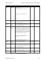
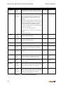
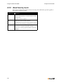
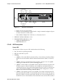
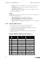
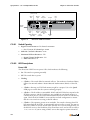
Specifications – SG 1-U Half-Width Switches
Chapter C: ShoreGear Switches
— 2 flashes—The switch failed its internal self-test. This indicates a hardware failure.
Replace the unit and submit a Return Material Authorization (RMA) to ShoreTel,
Inc.
— 3 flashes—Booting via FTP. Flash memory might be corrupted. Go to the Quick
Look page to ensure that the system is running properly.
— 4 flashes—The IP address is unavailable. DHCP and BOOTP did not respond to the
IP address request, and the IP address is not available in nonvolatile memory to
continue boot process. The switch will automatically reboot in five seconds and try
again. Check the BOOTP/DHCP server and the network configuration to ensure
that the voice switch is receiving a valid IP address.
— 5 flashes—The operating system is not available. The switch is booting from FTP
but cannot find the boot files. It automatically reboots in five seconds. You can use
BOOTP or DHCP to tell the switch where the files are. If you are using BOOTP, set
the BOOTP server to the IP address of the ShoreWare server, and set the boot file to
/tsk/vxworks. If you are using a DHCP server that supports options 66 and 67,
set option 66 to the ShoreWare server’s IP address, and set option 67 to /tsk/
vxworks.
— 6 flashes—Using a previously stored IP address. A BOOTP/DHCP transaction was
attempted, but the BOOTP/DHCP server did not respond. The switch continues to
use the IP address stored in nonvolatile memory until it receives a valid response. If
the switch receives a response that provides a different IP address, it reboots using
the new IP address. If the switch receives a response that matches the IP address
stored in nonvolatile memory, it continues operation, and the power LED stops
flashing. If the problem persists, check the BOOTP/DHCP server and network
configuration.
Network LEDs
The ShoreGear 90 network LEDs (LAN1 and LAN2) indicate the speed at which the switch
is communicating with the network and whether there is network activity.
When both LAN connectors are connected into a redundant network configuration, one
network port is active while the other is in standby mode. If one LAN connection fails, the
switch activates the other port.
The network LED descriptions are as follows:
•
Link/Activity: When lit, this LED indicates that the switch is connected to an Ethernet
network. This LED indicates network activity, as follows:
— When flashing, network activity is detected.
— When on (not flashing), the switch is connected to an Ethernet network.
— When off, the switch cannot detect an Ethernet network.
This LED is not directly related to any switch’s individual network activity. For
example, if three switches are connected to the same hub and one switch’s Traffic LED
shows activity, the other switches will indicate the same activity.
•
100M:
— When green, the switch is connected to a 100BaseT network.
— When off, the switch is connected to a 10BaseT network.
Status LED
The ShoreGear 90 has one status LED to provide general information about the ports. The
color and blink pattern of the LED indicate the port function:
200