1
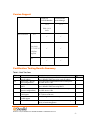
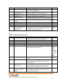
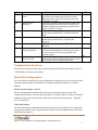
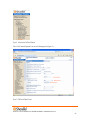
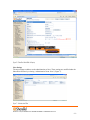
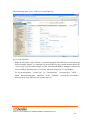
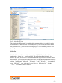
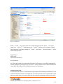
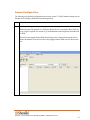
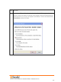
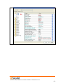
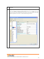
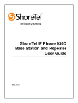
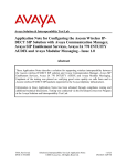
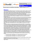
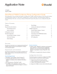
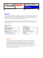
T P P A P P N O T E TPP: 10104 Date: June, 2010 Product: ShoreTel | Ascom i75 System version: ShoreTel 10.1 Abstract The Ascom i75® VoWiFi handset is a wireless 802.11 telephone available in three versions: the Protector, the Medic, and the Messenger model. The Protector and Medic versions include mobile alarming, text messaging, and voice services. The Messenger version includes text messaging and voice services only. All versions are robust units designed to function in tough environments. Combining ShoreTel® IP-PBX together with Ascom i75 VoWiFi handsets allows our customers the opportunity to utilize ShoreTel’s unique distributed call control architecture and Ascom’s rugged, featurerich wireless i75 handsets. Table of Contents Overview ..................................................1 Features and Benefits ...................................2 Ascom Overview and Contact .........................2 Ascom Product Information ............................3 Architecture Overview ..................................3 Requirements, Certification and Limitations .......4 Version Support ..........................................5 Certification Testing Results Summary ..............5 Table 1: Basic Test Cases ............................... 5 Table 2: Extended Feature Test Cases ............... 6 Configuration Overview ................................ 7 ShoreTel Configuration ................................. 7 Ascom Configuration .................................. 19 Ascom Troubleshooting ............................... 28 Ascom Technical Support ............................ 28 ShoreTel Technical Support ......................... 28 Document and Software Copyrights................ 29 Trademarks ............................................. 29 Disclaimer ............................................... 29 Company Information ................................. 29 Overview This Application Note describes the configuration process necessary to provide interoperability between ShoreTel Unified Communications solution and Ascom wireless i75 VoWiFi Session Initiation Protocol (SIP) handsets. Specific calling features tested and verified to operate correctly include attended/unattended transfer, conference call participation, conference call add/drop, conference call creation, multiple call appearances, caller ID operation, call forwarding unconditional, call forwarding on busy, call forwarding clear, pick groups, call pickup, bridged appearances, voicemail, MWI, hold and return from hold. Features and Benefits Ascom i75® VoWiFi handsets: Ruggedized handset Professional messaging Standards-based Large display Personal alarming Longest industry talk time Ascom Overview and Contact Sales support for the Ascom i75 VoWiFi handset can be obtained through the following: For local US/Canada: Phone: 1-877-71ASCOM or 1-877-712-7266 Internet: http://www.ascom.us/us-en/index-us/products-solutions/sales-us.htm (for your Regional Sales Director) Email: [email protected] (for Technical support) For international customers: Internet: www.ascom.com/ws and select your country of interest, to find local sales and support contact information. 960 Stewart Drive Sunnyvale, CA 94085 USA Phone +1.408.331.3300 +1.877.80SHORE Fax +1.408.331.3333 www.ShoreTel.com -2- Ascom Product Information i75 VoWiFi SIP handsets—the Protector, Medic and Messenger models of Ascom i75—are shown below. Architecture Overview The network diagram shown below illustrates the testing environment used for compliance testing. The network consists of: a ShoreTel ShoreWare® Director, a ShoreTel Personal Call Manager, three different models of ShoreTel IP telephones (IP110, IP230, and IP560), three Ascom wireless i75 handsets, one non wireless non IP telephone, and a wireless network infrastructure providing network services such as Dynamic Host Configuration Protocol (DHCP),Trivial File Transfer Protocol (TFTP) and an access point (AP). 960 Stewart Drive Sunnyvale, CA 94085 USA Phone +1.408.331.3300 +1.877.80SHORE Fax +1.408.331.3333 www.ShoreTel.com -3- ShoreGear Figure 1 – Testing Environment Requirements, Certification and Limitations Ascom Portable Device Manager (PDM) requirements include: PC with Windows XP® Professional SP2 or Windows Vista® Business operating system Sun Java Runtime Environment (JRE) 6 or higher Microsoft Internet Explorer 6.0TM (IE6) or higher USB port (USB 1.1 required, USB 2.0 supported) Acrobat Reader 4.0 or higher The i75 VoWiFi handset’s SIP Call Manager must be on the same ShoreGear® switch that is configured as the SIP Proxy switch. 960 Stewart Drive Sunnyvale, CA 94085 USA Phone +1.408.331.3300 +1.877.80SHORE Fax +1.408.331.3333 www.ShoreTel.com -4- Version Support Ascom i75 VoWiFi Handset Ascom Protable Device Manager 1.6.12 3.1.8 With v1.6.14 hotfix ShoreTel Release 8.0 8.1 Note: build 13.23.6912.0 or higher required 10.1 Certification Testing Results Summary Table 1: Basic Test Cases ID Name Description 1.1 Device initialization with static IP address Device reset – idle (for static configurations) Device initialization with DHCP Device reset – idle (for dynamic configurations) Verify Diffserv Code Point support Verify Date and Time Update support Place call Verify successful startup and initialization of the device up to a READY/IDLE state using a static IP address Verify successful re-initialization of device after power loss while device is idle Verify successful startup and initialization of the device up to a READY/IDLE state using DHCP Verify successful re-initialization of device after power loss while device is idle Verify the ability to set Diffserv Code Point from SIP DUT (device under test) Verify setting of Date and Time Update on SIP DUT 1.2 1.3 1.4 1.5 1.6 1.7 Verify successful call placement with normal dialing to a variety of terminating phones Results Pass Pass Pass Pass Not Tested Pass Pass 960 Stewart Drive Sunnyvale, CA 94085 USA Phone +1.408.331.3300 +1.877.80SHORE Fax +1.408.331.3333 www.ShoreTel.com -5- ID Name Description Results 1.8 Receive call Pass 1.9 CODEC support (DUT to ShoreTel Phone) CODEC support (DUT to SIP reference) CODEC negotiation Verify successful call placement with normal dialing to a variety of terminating phones Verify successful call connection and audio path using all supported CODECs (G.711-Ulaw and G.729) Verify successful call connection and audio path using all supported CODECs (G.711-Ulaw and G.729) Verify successful negotiation between devices configured with different default CODECs (G.711-Ulaw and G.729) Verify successful hold and resume of connected call Verify successful hold and resume of connected call Verify successful forwarding of incoming calls Verify successful forwarding of incoming calls Verify successful transmission of in-band and out-ofband digits (RFC2833) for calls placed to and from the DUT with a variety of other devices Pass Pass Pass Pass RFC2833 only 1.10 1.11 1.12 1.13 1.14 1.15 1.16 Hold DUT to SIP reference Hold DUT to ShoreTel Forward Forward from SIP DUT Dual-tone multifrequency (DTMF) transmission Pass Pass Pass Pass Table 2: Extended Feature Test Cases ID Name Description Notes 2.1 Call waiting Pass 2.2 2.3 2.4 2.5 2.6 Park Transfer – blind Transfer – monitored Conference – ad hoc Caller ID Verify appropriate notification and successful connection of incoming call while busy with another party Verify successful park and retrieval of connected call Verify successful blind transfer of connected call Verify successful monitored transfer of connected call Verify successful ad hoc conference of three parties Verify that Caller ID name and number is sent and received from SIP endpoint device Verify dialing “911” on DUT could connect with “911” services Verify that calls are properly terminated on the ShoreTel Auto Attendant menu and that you can transfer to the desired extension. Verify that calls are properly terminated on the ShoreTel Auto Attendant menu and that you can transfer to the desired extension using the “Dial by Name” feature. Verify that calls are properly terminated on the ShoreTel Auto Attendant menu and that you can transfer to the Voice Mail Login Extension. Not Tested 2.7 911 2.8 Auto Attendant Menu 2.9 Auto Attendant Menu “Dial by Name” 2.10 Auto Attendant Menu checking Voice Mail mailbox Pass Pass Pass Pass Pass, displays Caller Name only on LCD, but it does have the Caller ID in history. Pass Pass Pass 960 Stewart Drive Sunnyvale, CA 94085 USA Phone +1.408.331.3300 +1.877.80SHORE Fax +1.408.331.3333 www.ShoreTel.com -6- ID Name Description 2.11 Initiate call to a Hunt Group 2.12 Initiate call to a Workgroup 2.13 Hunt Group Member 2.14 Workgroup Agent 2.15 Call Forward – “FindMe” 2.16 ShoreTel Converged Conferencing Server 2.17 Bridged Call Appearance (BCA) extension Initiate a call from DUT and verify that calls route to the proper Hunt Group and are answered by an available hunt group member with audio in both directions using G.729 and G.711 codecs. Initiate a call from DUT and verify that calls route to the proper Workgroup and are answered successfully by an available workgroup agent with audio in both directions using G.729 and G.711 codecs. Verify that incoming calls to a hunt group can be answered properly when DUT is a member of the hunt group. Verify that incoming calls to a workgroup can be answered properly when DUT is an agent of the workgroup. Verify that calls are forwarded to DUT’s “FindMe” destination. Verify that calls are properly forwarded to the ShoreTel Converged Conferencing Server and it properly accepts the access code and you’re able to participate in the conference bridge. Verify that calls are properly presented to all of the phones that have BCA configured and that the call can be answered, placed on-hold and then transferred. Notes Pass Pass Pass Pass Pass Pass Pass Configuration Overview This document describes the major steps needed to configure the ShoreTel system and the Ascom i75 VoWiFi handset so that they work together. ShoreTel Configuration This section describes the ShoreTel system configuration to support the Ascom. The section is divided into general system settings and individual user configuration needed to support the i75 VoWiFi handsets. ShoreTel System Settings - General The first settings to address within the ShoreTel system are the general system settings. These configurations include the call control, the switch and the site settings. If these items have already been configured on the system, skip this section and go on to the “ShoreTel System Settings – Individual Users” section below. Call Control Settings The Call Control Options within ShoreWare Director may need to be reconfigured. To configure these settings for the ShoreTel system, log into ShoreWare Director and select Administration, Call Control and then Options (Figure 2). 960 Stewart Drive Sunnyvale, CA 94085 USA Phone +1.408.331.3300 +1.877.80SHORE Fax +1.408.331.3333 www.ShoreTel.com -7- Figure 2 – Administration Call Control/Options The “Call Control/Options” screen will then appear (Figure 3). Figure 3 – Call Control/Options Screen 960 Stewart Drive Sunnyvale, CA 94085 USA Phone +1.408.331.3300 +1.877.80SHORE Fax +1.408.331.3333 www.ShoreTel.com -8- If this is an upgrade from previous ShoreTel versions, you may see a parameter named “Always Use Port 5004 for RTP.” If so, you will need to disable this parameter by unchecking the box and saving the setting. When enabled, SIP extension configuration will fail. It is also important to note that this “one time” setting requires a system restart (all servers first, then ShoreGear switches followed by IP Phones) to take effect. Once the server has been restarted, this configuration parameter will no longer be visible, or may be grayed out. The default for new installations is disabled, thus the parameter is not visible (as shown in Figure 3). Realm: The realm is used in authenticating all SIP devices. It is typically a description of the computer or system being accessed. Changing this value will require reboot of switches serving as SIP extensions. It is not necessary to modify this parameter to get the i75 VoWiFi handsets functional. SIP session interval: Session interval value indicates the session (call) “keep alive” period. There is no need to modify the default value of “3600” seconds. SIP session refresher: The refresher setting decides if user agent client or user agent server refreshes the session. Again, there is no need to modify the default value of “Caller (UAC).” This allows the i75 VoWiFi handset to be in control of the session timer refresh. Switch Settings When allocating Ports for SIP extensions, these changes are modified by selecting “Administration,” then “Switches” in ShoreWare Director (Figure 4). Figure 4 – Administration/Switches 960 Stewart Drive Sunnyvale, CA 94085 USA Phone +1.408.331.3300 +1.877.80SHORE Fax +1.408.331.3333 www.ShoreTel.com -9- This action brings up the “Switches” screen. From the “Switches” screen, simply select the name of the switch to configure. The “Edit ShoreGear …Switch” screen will be displayed. Within the “Edit ShoreGear …Switch” screen, define one of the “Port Type” settings from the available ports to “100 SIP Proxy” (Figure 5), then save the change. Note: If your installation requires more than 100 SIP extensions configure the “Port Type” as “100 SIP Proxy” as necessary (i.e,. two ports configured for “100 SIP Proxy” will provide 200 SIP extensions). Figure 5 – Edit Switches If the ShoreGear switch that you have selected has “built-in” capacity (i.e., ShoreGear 50/90/220T1/E1, etc.) for IP phones and SIP trunks, you can also remove 5 ports from the total number available to provide the “100 SIP Proxy” configuration necessary (Figure 6). Note: Every 5 ports you remove from the total available will result in “100 SIP Proxy” ports being made available. One dedicated ShoreGear 120 switch can act as a proxy for the entire site and support up to 2400 SIP phones. 960 Stewart Drive Sunnyvale, CA 94085 USA Phone +1.408.331.3300 +1.877.80SHORE Fax +1.408.331.3333 www.ShoreTel.com - 10 - Figure 6 – ShoreGear Switch Built-in Capacity Sites Settings The next settings to address are the administration of sites. These settings are modified under the ShoreWare Director by selecting “Administration” then “Sites” (Figure 7). Figure 7 – Administration/Sites 960 Stewart Drive Sunnyvale, CA 94085 USA Phone +1.408.331.3300 +1.877.80SHORE Fax +1.408.331.3333 www.ShoreTel.com - 11 - This selection brings up the “Sites” screen. Within the “Sites” screen, select the name of the site to configure. The “Edit Site” screen will then appear. Scroll down to the “SIP Proxy” parameters (Figure 8). Figure 8 – Site Screen SIP Proxies The “Virtual IP Address” parameter is a new configuration parameter with ShoreTel 8. This “Virtual IP Address” is an IP address that can be moved to a different switch during a failure. For each site that supports SIP extensions, one “Virtual IP Address” is defined that will act as the SIP Proxy for the site. This IP address must be unique and static. The ShoreTel server will assign this “Virtual IP Address” to the ShoreGear that is configured as SIP proxy for the site. Two ShoreGear switches can be configured as SIP proxy servers for redundancy and reliability purposes. If the primary proxy server goes down, the other proxy switch will take over the “Virtual IP Address.” Due to this “Virtual IP Address” mechanism, SIP phones will not know if the proxy switch goes off-line. Note: If you choose not to define a “Virtual IP Address,” you can only define one proxy switch, and there is no redundancy or failover capabilities. The switches available in the “Proxy Switch 1 / 2” will only be shown if proxy resources have been enabled on the switch. 960 Stewart Drive Sunnyvale, CA 94085 USA Phone +1.408.331.3300 +1.877.80SHORE Fax +1.408.331.3333 www.ShoreTel.com - 12 - NOTE: Currently the “Virtual IP Address” SIP Proxy should not be configured for use with the i75 VoWiFi handsets, as the i75 requires that the SIP Call Manager and SIP Proxy be on the same ShoreGear switch. The Admission Control Bandwidth defines the bandwidth available to and from the site. This is important as SIP endpoints may be counted against the site bandwidth. See the ShoreTel Planning and Installation Guide for more information about this. ShoreTel 8 now adds 10 CODECs by default. These CODECs can be grouped as “Codec Lists” and defined in the sites page for “Inter-site” and “Intra-site” calls. See the ShoreTel 8 Server Release Notes for more information. The default settings will work properly with the Ascom i75 VoWiFi handsets. Creating SIP Extension You need to create a user extension for the i75 VoWiFi handset. This is accomplished from ShoreWare Director by selecting “Administration” followed by “Users…,” then “Individual Users.” This action will bring up the “Individual Users” screen at the top of the page. To the right of “Add new user at site:,” select the site you wish to create the user in (from the drop down menu), and select “Go” (Figure 9). Figure 9 – Trunk Groups Settings 960 Stewart Drive Sunnyvale, CA 94085 USA Phone +1.408.331.3300 +1.877.80SHORE Fax +1.408.331.3333 www.ShoreTel.com - 13 - This action brings up the “Users” “Edit Users” screen (Figure 10). Figure 10 – Adding/Editing Users Define the “First Name” and “Last Name” as you deem appropriate. ShoreWare Director will auto-assign the next available “Number” (i.e. extension), but you can modify it to any available extension. Define the “License Type” as needed, in this example we chose “Extension and Mailbox” although it’s not necessary to have a mailbox. Define the proper “User Group” and set the “Home Port” to “Any IP Phone.” Note: If you configured the “License Type” for “Extension-Only,” you cannot select “Any IP Phone” but instead must set the “Home Port” for the “SoftSwitch” selection. Save your changes, then scroll down to the “SIP Password:” section (Figure 11). 960 Stewart Drive Sunnyvale, CA 94085 USA Phone +1.408.331.3300 +1.877.80SHORE Fax +1.408.331.3333 www.ShoreTel.com - 14 - Figure 11 – Individual User SIP Settings There is no default “SIP Password,” it is masked with the appearance that there is, but don’t be confused to think that there’s a default password. You can modify it to any value you wish, but be certain to note what you changed it to, as you will need it when configuring the i75 VoWiFi handset parameters. Save your changes. SIP Profiles ShoreWare Director’s “Call Control…” section contains an “SIP Profiles” option. ShoreTel 8 comes standard with a “_System” and “_ShorePhoneIP8000” SIP profiles (they cannot be deleted - only disabled). By default, the Ascom i75 VoWiFi handsets utilize the “_System” profile. In order to optimize the functionality, you will need to add a custom profile. This is accomplished from ShoreWare Director by selecting “Administration” followed by “Call Control…,” then “SIP Profiles.” This action brings up the “SIP Profiles” screen. At the top of the page, below the “SIP Profiles List”, select the “New…” radio button, as shown in Figure 12. 960 Stewart Drive Sunnyvale, CA 94085 USA Phone +1.408.331.3300 +1.877.80SHORE Fax +1.408.331.3333 www.ShoreTel.com - 15 - Figure 12 – SIP Profiles This action brings up the “Edit SIP Profile” screen, Figure 13. 960 Stewart Drive Sunnyvale, CA 94085 USA Phone +1.408.331.3300 +1.877.80SHORE Fax +1.408.331.3333 www.ShoreTel.com - 16 - Figure 13 – Edit SIP Profile Define a “Name:” for the entry, and be sure to define an appropriate name. For the “User Agent:” option, enter “Ascom i75” (without quotes); the “Priority:” defaults to 100, no change is required. Enable the profile by checking (enabling) the “Enable” option. In the “Custom Parameters:” options, add the following entries: OptionsPing=1 MWI=notify FakeDeclineAsRedirect=1 Save the changes. Note: Please do not disable any of the default SIP profiles. In case there are issues with the custom profile defined, disabling the system profiles may cause the i75 VoWiFi handsets to not be added to the ShoreTel system. Refer to the ShoreTel 8 Server Release Notes for more information. IP address Phone Map As noted earlier, the Ascom i75 VoWiFi handsets require that the SIP Call Manager and SIP Proxy reside on the same ShoreGear switch. To accomplish this, you will be required to create a site and define a single ShoreGear switch at this site. For more information on creating sites and adding switches, please refer to 960 Stewart Drive Sunnyvale, CA 94085 USA Phone +1.408.331.3300 +1.877.80SHORE Fax +1.408.331.3333 www.ShoreTel.com - 17 - the ShoreTel Planning and Installation Guide. Then create an “IP Address Phone Map”. You can do so via ShoreWare Director, navigating to the “Administration,” “IP Phones…,” “IP Address Phone Map” screen, then adding an entry for the desired site, with the IP address range of the i75 VoWiFi handsets. Note: Be sure to only add one switch at this site and make this switch the SIP Proxy switch for the site. Note that with multiple switches at the site, when the i75 registers, the SIP Call Manager (registrar switch) could be a switch different than the SIP Proxy switch, since the ShoreWare server will always attempt to load balance IP endpoints. This is a temporary workaround until future development is completed allowing for the Ascom i75 to be registered to a different SIP Call Manager ShoreGear switch and the SIP Proxy ShoreGear switch. This does create some limitations that you should be aware of: Single point of failure (since only one ShoreGear switch can be utilized) Can only scale to 220 i75 VoWiFi handsets per defined site Additional costs (since a single ShoreGear switch must be dedicated to the Ascom i75 VoWiFi handsets) This completes all of the ShoreTel configuration parameters necessary to install the Ascom i75 VoWiFi handsets. 960 Stewart Drive Sunnyvale, CA 94085 USA Phone +1.408.331.3300 +1.877.80SHORE Fax +1.408.331.3333 www.ShoreTel.com - 18 - Ascom Configuration The following steps detail the configuration process for the Ascom i75 VoWiFi handset using the Ascom Portable Device Manager (PDM) Windows-based application. Step Description 1 Launch the PDM application from the computer that has the application installed and has the PDM cradle physically attached via a USB cable. Before the user is presented with the following screen, a login is required. See Section 10 [3] for administration and configuration information on the PDM. After the user has logged onto the PDM, the following screen is displayed showing the devices found in the database. Since no devices have been plugged into the PDM, none are shown at this time. 960 Stewart Drive Sunnyvale, CA 94085 USA Phone +1.408.331.3300 +1.877.80SHORE Fax +1.408.331.3333 www.ShoreTel.com - 19 - Step Description 2 Once an Ascom i75 portable handset is placed into the cradle, the PDM recognizes the telephone and cross references the database of telephones. If the telephone is not found in the database, the PDM prompts the user to save the new telephone to the database. Click the radio button labeled Edit parameters and then click Next. 960 Stewart Drive Sunnyvale, CA 94085 USA Phone +1.408.331.3300 +1.877.80SHORE Fax +1.408.331.3333 www.ShoreTel.com - 20 - Step Description 3 Navigate to the “System -> A” configuration page by clicking System and then A. Configure the following parameters. These settings should be repeated for each Ascom i75 VoWiFi handset being provisioned. The ESSID field value must match the ESSID value specified in the AP. Note: Different security schemas can be used. The following screen shot shows: DHCP mode “Enable” ESSID “merusid” Security mode “Open” Encryption type “NONE” IP DSCP for voice “0x2e (46) – Expedited Forwarding” IP DSCP for signaling “0x1A (26) – Assured Forwarding 31” 960 Stewart Drive Sunnyvale, CA 94085 USA Phone +1.408.331.3300 +1.877.80SHORE Fax +1.408.331.3333 www.ShoreTel.com - 21 - 960 Stewart Drive Sunnyvale, CA 94085 USA Phone +1.408.331.3300 +1.877.80SHORE Fax +1.408.331.3333 www.ShoreTel.com - 22 - Step Description 4 Navigate to the “Device -> User” configuration page by clicking Device and then User. Configure the following parameters. The User display text field does not need to be the extension assigned to the handset. This field can hold a 32 character alpha-numeric value which can display proper names. Repeat this process for each Ascom i75 VoWiFi handset being provisioned and modify the parameters to be unique per handset. The following screen shot shows: User display text “1703” Endpoint number “1703” Endpoint ID “Test Phone” 960 Stewart Drive Sunnyvale, CA 94085 USA Phone +1.408.331.3300 +1.877.80SHORE Fax +1.408.331.3333 www.ShoreTel.com - 23 - Step Description 5 Navigate to the “Device -> General” configuration page by clicking Device and then General. Ensure that the Replace Call Rejected with User Busy field value is set to Enable. If this value is not set correctly, certain calling features such as transfer will not operate properly. This setting should be repeated for each Ascom i75 VoWiFi handset being provisioned. 960 Stewart Drive Sunnyvale, CA 94085 USA Phone +1.408.331.3300 +1.877.80SHORE Fax +1.408.331.3333 www.ShoreTel.com - 24 - Step Description 6 Navigate to the “Device -> Unite” configuration page by clicking Device and then Unite. Configure the following parameters. The IMS phone number should be the extension associated with the Ascom i75 VoWiFi handset being provisioned. This setting should be repeated for each Ascom i75 VoWiFi handset being provisioned. This setting is made to allow the handset phone number to appear in the PDM screen. 960 Stewart Drive Sunnyvale, CA 94085 USA Phone +1.408.331.3300 +1.877.80SHORE Fax +1.408.331.3333 www.ShoreTel.com - 25 - Step Description 7 Navigate to the “Protocols -> General” configuration page by clicking Protocols and then General. Configure the following parameters. These settings should be repeated for each Ascom i75 VoWiFi handset being provisioned. VoIP protocol “SIP” Coder configuration “G.711 u-law” 960 Stewart Drive Sunnyvale, CA 94085 USA Phone +1.408.331.3300 +1.877.80SHORE Fax +1.408.331.3333 www.ShoreTel.com - 26 - Step Description 8 Navigate to the “Protocols -> SIP” configuration page by clicking Protocols and then SIP. Configure the following information and then click OK The SIP proxy password field must match the Media Server Extension password configured on ShoreTel IP-PBX. Once the information has been configured, the PDM reports the information as ***********. After clicking OK, pick up the telephone from the PDM cradle in order to reboot the handset and activate the new configuration. Repeat Steps 1 – 8 for each Ascom i75 portable handset being provisioned, but modify the appropriate extension fields to avoid duplication. The following screen shot shows: SIP proxy IP address “172.20.106.114” SIP proxy password “123456” SDP media mode attribute “Media Attribute” 960 Stewart Drive Sunnyvale, CA 94085 USA Phone +1.408.331.3300 +1.877.80SHORE Fax +1.408.331.3333 www.ShoreTel.com - 27 - Ascom Troubleshooting For troubleshooting of the Ascom i75 handset, see the following Ascom documentation: User Manual – Ascom i75 VoWiFi Handset TD92319GB Ascom Technical Support Technical support for the Ascom i75 VoWiFi handset can be obtained through the following: Phone: 1-877-71ASCOM or 1-877-712-7266 Email: [email protected] ShoreTel Technical Support ShoreTel technical support can be obtained through the following: Phone: +1 800 742-2348 Web: www.support.shoretel.com 960 Stewart Drive Sunnyvale, CA 94085 USA Phone +1.408.331.3300 +1.877.80SHORE Fax +1.408.331.3333 www.ShoreTel.com - 28 - Document and Software Copyrights Copyright © 2008 by ShoreTel, Inc., Sunnyvale, California, U.S.A. All rights reserved. Printed in the United States of America. Contents of this publication may not be reproduced or transmitted in any form or by any means, electronic or mechanical, for any purpose, without prior written authorization of ShoreTel Communications, Inc. ShoreTel, Inc. reserves the right to make changes without notice to the specifications and materials contained herein and shall not be responsible for any damage (including consequential) caused by reliance on the materials presented, including, but not limited to typographical, arithmetic or listing errors. Trademarks The ShoreTel logo, ShoreTel, ShoreCare, ShoreGear, ShoreWare and ControlPoint are registered trademarks of ShoreTel, Inc. in the United States and/or other countries. ShorePhone is a trademark of ShoreTel, Inc. in the United States and/or other countries. All other copyrights and trademarks herein are the property of their respective owners. Disclaimer To be “ShoreTel Certified” means that Technology Partner's product will interoperate with the ShoreTel system, but ShoreTel does not certify that the features or functionality of Technology Partner's product will perform as specified by Technology Partner nor that Technology Partner's product will meet your specific application needs or requirements. To inter-operate means that Technology Partner's product is able to exchange, use and share information with the ShoreTel system. Company Information ShoreTel, Inc. 960 Stewart Drive Sunnyvale, California 94085 USA +1.408.331.3300 +1.408.331.3333 fax 960 Stewart Drive Sunnyvale, CA 94085 USA Phone +1.408.331.3300 +1.877.80SHORE Fax +1.408.331.3333 www.ShoreTel.com - 29 -