1
Stock Flight Systems
Schützenweg 8a
82335 Farchach
Germany
CANflight
User's Manual
V 1.1
Document: CANflight_Users_Manual.pdf
Page 1 of 23
© Stock Flight Systems 2011
Project:
Author: M. Stock
Date: 11.10.2011
CANflight
Rev.: 1.1
Stock Flight Systems
Schützenweg 8a
82335 Farchach
Germany
CANflight
User's Manual
V 1.1
Table of Contents
1 Introduction....................................................................................................................................................... 3
2 Front Panel Connectors and Indicators............................................................................................................ 5
3 Rear Panel Connectors.................................................................................................................................... 9
4 Ethernet Interface........................................................................................................................................... 11
5 CANflight Configuration.................................................................................................................................. 12
6 CANflight Firmware Upgrades........................................................................................................................ 16
7 CANflight Application Programmer's Interface................................................................................................ 17
7.1 Pmc825StartInterface().......................................................................................................................... 18
7.2 Pmc825StopInterface().......................................................................................................................... 18
7.3 Pmc825RawCanRead() ........................................................................................................................ 18
7.4 Pmc825RawCanWrite() ......................................................................................................................... 18
7.5 Pmc825CanAerospaceRead() ............................................................................................................... 19
7.6 Pmc825CanAerospaceWrite() ............................................................................................................... 19
7.7 Pmc825Arinc825Read() ........................................................................................................................ 20
7.8 Pmc825Arinc825Write() ........................................................................................................................ 20
7.9 Pmc825CtrlRead() ................................................................................................................................. 20
7.10 Pmc825CtrlWrite() ............................................................................................................................... 21
8 The XCT Toolbox............................................................................................................................................ 22
9 CANflight Supplier List................................................................................................................................... 23
10 ARINC825/CANaerospace Websites............................................................................................................ 23
Table of Figures
Figure 1.1: CANflight Hardware........................................................................................................................... 3
Figure 1.2: CANflight Block Diagram................................................................................................................... 4
Figure 2.1: CANflight Front Panel........................................................................................................................ 5
Figure 2.2: RJ-54 Connector with Status LEDs................................................................................................... 7
Figure 2.3: Typical µSDHC Card......................................................................................................................... 8
Figure 2.4: µSDHC Pinout................................................................................................................................... 8
Figure 2.5: Mating DC Coaxial Plug.................................................................................................................... 8
Figure 2.6: Lock-Tab DC Coaxial Connector Pinout............................................................................................ 8
Figure 2.7: Type B USB Connector Pinout.......................................................................................................... 9
Figure 3.1: CANflight Rear Panel........................................................................................................................ 9
Figure 3.2: CAN1/CAN2 D-Sub Connector Pinout............................................................................................ 10
Figure 3.3: Mating IRIG-B SMA Plug................................................................................................................. 10
Figure 4.1: CANflight/Host Computer Communication Network........................................................................ 11
Figure 8.1: XCT Main Window........................................................................................................................... 22
Document: CANflight_Users_Manual.pdf
Page 2 of 23
© Stock Flight Systems 2011
Project:
Author: M. Stock
Date: 11.10.2011
CANflight
Rev.: 1.1
CANflight
User's Manual
V 1.1
Stock Flight Systems
Schützenweg 8a
82335 Farchach
Germany
1
Introduction
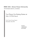
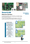
The CANflight interface system offers 2 optically isolated CAN 2.0B interfaces according to ISO 11898, an
IRIG-B time code input and a 10/100/1000 BaseT Ethernet interface. To minimize CPU load on host
computers, the CANflight uses an onboard Xilinx Spartan-3 FPGA with dual Microblaze processors and 8
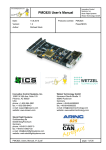
MByte SRAM to process and store CAN messages. The CAN bus interfaces are accessible via two 9 pin DSub connectors in the rear. Figure 1.1 shows the CANflight hardware.
Figure 1.1: CANflight Hardware
The CANflight features are:
• Laptop-ready, Dual Core Processor Based Embedded Realtime Control System for Ground and Airborne
Use
• Two isolated, fully independant Controller Area Network (ISO 11898), ARINC825 and CANaerospace
protocol compliant interfaces
• Integrated µSDHC card-based Flight Data Recording Option available
• IRIG-B Time Code Input for High Precision Data Synchronization
• Auto-negotiating 10/100/1000 BaseT Ethernet interface with CANaerospace over Ethernet (CoE) and
ARINC825 over Ethernet (A825oE) protocol and Application Programmer Interface (API)
• IEEE 802.11 Wireless LAN Option with CANaerospace over Wireless (CoW) and ARINC825 over Wireless
(A825oW) protocol available
• Frontpanel Activity LEDs for CAN and Ethernet
• Power Supply using USB cable or EN2282 Aircraft Power (9-36VDC)
• Mechanical Dimensions 80mm x 47mm x 132mm, weight 320g
• CAN/ARINC825/CANaerospace toolbox for Linux, MacOS and Windows
• Custom Software Options available on request
The CANflight is a standalone computer system that utilizes its processing power to relief external computer
systems from the tasks of transmitting, receiving, buffering and pre/postprocessing low, medium or high-speed
CAN, CANaerospace and ARINC 825 messages. It can handle up to 100% bus load at the maximum CAN
data rate of 1MBit/s on both channels without data loss. The driver software provides an easy-to-handle
function call interface for CAN bus message transmission and reception including support for the
CANaerospace and ARINC 825 higher layer protocols. The CANflight software consists of host drivers for
various operating systems and platforms, sample “C” source code and the XCT toolbox connected to the
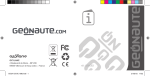
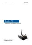
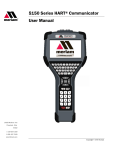
CANflight via Ethernet/UDP/IP. Figure 1.2 shows the CANflight block diagram.
Document: CANflight_Users_Manual.pdf
Page 3 of 23
© Stock Flight Systems 2011
Project:
Author: M. Stock
Date: 11.10.2011
CANflight
Rev.: 1.1
CANflight
User's Manual
V 1.1
Stock Flight Systems
Schützenweg 8a
82335 Farchach
Germany
Figure 1.2: CANflight Block Diagram
Document: CANflight_Users_Manual.pdf
Page 4 of 23
© Stock Flight Systems 2011
Project:
Author: M. Stock
Date: 11.10.2011
CANflight
Rev.: 1.1
CANflight
User's Manual
V 1.1
Stock Flight Systems
Schützenweg 8a
82335 Farchach
Germany
The CANflight CAN 2.0B interfaces are implemented with licensed Bosch C_CAN controller IP cores to ensure
compatibility with the Bosch CAN standard and to allow precise hardware timing and control over the
transmission and reception of CAN/ARINC825/CANaerospace messages. The Xilinx FPGAs and the
CANflight firmware provide local buffering and 60ns time stamp resolution for all CAN messages and
implement ARINC825/CANaerospace specific protocol functions. High precision time synchronization of CAN
messages is accomplished though an IRIG-B time code input providing 1µs resolution. An integrated µSDHC
interface is used for data acquisition storage, system configuration information and firmware upgrades.
CANflight is integrated into a rugged aluminum box which is powered from 9-36 VDC allowing it to run from
standard 14V or 28V DC aircraft power buses according to the EN2282 specification. The power input lines
are protected against transient overvoltage and electromagnetic interference. Alternatively, CANflight runs off a
USB power connection for direct use with laptop computers. The total power consumption of a CANflight unit
is 5W. The CAN and Ethernet interfaces are serviced by different processors so that all interfaces may be
used at the same time without any loss of data. CANflight units may be connected to host computers using
CANaerospace/ARINC825 and the auto-negotiating 10/100/1000 BaseT Ethernet interface with the CAN over
Ethernet protocol standard developed by Stock Flight Systems. The Wireless LAN (IEEE 802.11) option for
CANflight provides an integrated DHCP server and a web-based configuration interface. The µSDHC card slot
accepts cards with sizes up to 16GBytes.
CANflight units can work as either standalone systems or as intelligent nodes within simple or complex CAN,
CANaerospace and ARINC825 networks. The interface between CANflight and host computer applications via
Ethernet/UPD/IP, either wired or wireless, is realized through a corresponding Application Programming
Interface (API) for a variety of operating systems including Linux, Solaris, MacOS, Windows and VxWorks.
2
Front Panel Connectors and Indicators
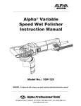
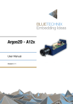
The CANflight front panel is shown in Figure 2.1, the usage of the various connectors and LEDs is described
in Table 2.1. Note that the CAN channels are numbered CH1 and CH2 for indications and connectors but are
referred to as channels 0 and 1 for all software functions including the configuration file (sections 5 CANflight
Configuration and 7 CANflight Application Programmer's Interface).
Figure 2.1: CANflight Front Panel
Document: CANflight_Users_Manual.pdf
Page 5 of 23
© Stock Flight Systems 2011
Project:
Author: M. Stock
Date: 11.10.2011
CANflight
Rev.: 1.1
CANflight
User's Manual
V 1.1
Stock Flight Systems
Schützenweg 8a
82335 Farchach
Germany
CANflight Front Panel Element
Description
ETHERNET Connector
Standard RJ-45 connector used for the interface between CANflight
and other computer systems using 10/100/1000 BaseT Ethernet.
The CANflight Ethernet supports auto-negotiating of the bus speed
as well as support for ICMP echo requests so that CANflight
systems respond to “ping” commands over the network.
9-36VDC Power Supply Connector Lock-Tab DC Coaxial Connector (Bayonet Lock) with 5.5mm outer
diameter to supply 9-36VDC to CANflight if the rear CAN connectors
or the USB connector are not used for that purpose. This power
connection is diode-decoupled from the Power supply contacts of
the CAN-Bus Connectors and electrically isolated from the USB
Power Connector.
USB Connector
Type-B USB connector, used to supply +5VDC power from an
external computer to the CANflight. The USB data connection is not
used. The maximum current drawn by the CANflight over this
connector is 0.5A. This USB power connection is isolated from the
other CANflight power connectors (9-36VDC Power Connector and
CAN-Bus Connectors).
Status LED
Bicolor LED which is illuminated in red during the start of the
CANflight firmware or in case of an internal system failure. This LED
flashes green during normal operation (with 90% on-time versus
10% off-time).
Left SSM LEDs
These LEDs flash to indicate that the associated CAN channel is
recording CAN messages on the µSDHC card. The longer the
respective LED is illuminated in green, the more CAN messages are
recorded over time (that is, the higher is the CAN bus load).
Right SSM LEDs
These LEDs indicate that the associated CAN channel is used for
data recording by the internal CANflight firmware. Both LEDs should
be illuminated continuously when data recording is activated.
TX LEDs
These LEDs flash with a frequency of 2Hz and a duty cycle of 50%
to indicate that the CANflight currently transmits CAN messages
over the associated channel.
RX LEDs
These LEDs flash with a frequency of 2Hz and a duty cycle of 50%
to indicate that the CANflight currently receives CAN messages over
the associated channel.
µSDHC Card Slot
The µSDHC card slot accepts regular µSD or µSDHC cards
formatted with a FAT-32 file system. Note that the cards have to be
inserted upside down (that is, with the gold contacts facing
upwards).
Table 2.1: CANflight Front Panel Elements
The CAN activity LEDs located on the front panel (TX, RX) indicate if a CAN channel transmits and/or receives
CAN messages. Every CAN channels has a dedicated RX/TX activity LED which flashes once for every
transmitted/received message or continuously at a rate of 2Hz in case of a steady message flow.
If the RX activity LED of a particular CAN channel stays dark in an active network, the physical interface
correctness of all network nodes including the used baud rates, sample points and termination resistors should
be verified.
Document: CANflight_Users_Manual.pdf
Page 6 of 23
© Stock Flight Systems 2011
Project:
Author: M. Stock
Date: 11.10.2011
CANflight
Rev.: 1.1
CANflight
User's Manual
V 1.1
Stock Flight Systems
Schützenweg 8a
82335 Farchach
Germany
The CANflight ETHERNET Connector has a pinout according to the established RJ-45 standard as shown in
Figure 2.2. This connector also contains two Status LEDS which indicate the negotiated Ethernet data rate
and interface transmit activity.
Speed LED
Green: 100 Mbit/s
Amber: 1 Gbit/s
Tx LED
12345678
Figure 2.2: RJ-54 Connector with Status LEDs
Table 2.2 shows the corresponding Ethernet signal assignment for the RJ-45 connector.
Pin
Signal Name
Signal Description
1
TX+
Transmit Data +
2
TX-
Transmit Data -
3
RX+
Receive Data +
4
N.C.
Not Connected
5
N.C.
Not Connected
6
RX-
Receive Data -
7
N.C.
Not Connected
8
N.C.
Not Connected
Table 2.2: RJ-45 Connector Signal Definition
CANflight offers a µSD card slot that supports FAT-32 formatted µSD and µSDHC cards. All standard µSD and
µSDHC cards with sizes ranging vom 2GB to 16GB maybe used with CANflight if they support the Serial
Peripheral Interface (SPI) mode and are capable of operating under a sustained SPI data rate of 25 Mhz.
The standard pinout of µSDHC cards is shown in Figure 2.4, the corresponding signal assignment in Table
2.3. Figure 2.3 shows a standard µSDHC card as an example. All standard µSD and µSDHC cards with sizes
ranging vom 1GB to 16GB maybe used with CANflight. The µSD card interface is fully compatible with the
µSD/HC specification of the SD Card Organization (www.sdcard.org).
The MicroSD card interface is used to configure the CANflight during startup using a dedicated configuration
file (see section 5 CANflight Configuration) and to perform firmware upgrades (see section 6 CANflight
Firmware Upgrades). Options for CAN data recording on µSDHC card are available on request.
Document: CANflight_Users_Manual.pdf
Page 7 of 23
© Stock Flight Systems 2011
Project:
Author: M. Stock
Date: 11.10.2011
CANflight
Rev.: 1.1
CANflight
User's Manual
V 1.1
Stock Flight Systems
Schützenweg 8a
82335 Farchach
Germany
Figure 2.3: Typical
µSDHC Card
Figure 2.4: µSDHC Pinout
Pin
Signal Name
Signal Description
1
RSD
Reserved
2
CS*
Chip Select (active low)
3
DI
Data In
4
VDD
Supply Voltage
5
SCK
System Clock
6
VSS
Supply Voltage Ground
7
DO
Data Out
8
RSD
Reserved
Table 2.3: µSDHC Connector Signal Definition
Figure 2.6 shows the pinout of the 9-36VDC Lock-Tab DC Coaxial Connector. This connector requires a
mating 2.5mm/5.5mm plug with the supply on the center contact and the Power Ground connection on the
outer ring. A mating (non-locked) plug is shown in Figure 2.5.
+ 9-36VDC
Power Ground
Figure 2.6: Lock-Tab DC Coaxial
Connector Pinout
Figure 2.5: Mating DC Coaxial
Plug
Figure 2.7 and Table 2.4 describe pinout and signals of the CANflight USB connector which is used for power
supply only.
Document: CANflight_Users_Manual.pdf
Page 8 of 23
© Stock Flight Systems 2011
Project:
Author: M. Stock
Date: 11.10.2011
CANflight
Rev.: 1.1
CANflight
User's Manual
V 1.1
Stock Flight Systems
Schützenweg 8a
82335 Farchach
Germany
2
1
3
4
Figure 2.7: Type B USB Connector
Pinout
Pin
Signal Name
Signal Description
1
Vcc
+ 5VDC/500mA
2
D-
Data – (Not used on CANflight)
3
D+
Data + (Not used on CANflight)
4
GND
Ground
Table 2.4: USB Connector Signal Definition
3
Rear Panel Connectors
The CANflight rear panel is shown in Figure 3.1. The CAN1/CAN2 Sub-D rear panel connectors combine the
CAN interfaces and the power supply as shown in Figure 3.2, the usage and pin assignment of the connectors
is described in Table 3.1.
Figure 3.1: CANflight Rear Panel
Document: CANflight_Users_Manual.pdf
Page 9 of 23
© Stock Flight Systems 2011
Project:
Author: M. Stock
Date: 11.10.2011
CANflight
Rev.: 1.1
CANflight
User's Manual
V 1.1
Stock Flight Systems
Schützenweg 8a
82335 Farchach
Germany
9876
54321
Figure 3.2: CAN1/CAN2 D-Sub
Connector Pinout
Pin
Signal Name
Signal Description
1
9 - 36VDC
Power Supply
2
CAN-L
CAN Low
3
Unused
Do not connect
4
Unused
Do not connect
5
DC Ground
Power Supply Ground
6
Unused
Do not connect
7
CAN-H
CAN High
8
Unused
Do not connect
9
Unused
Do not connect
Table 3.1: CAN1/CAN2 Connector Signal Definition
The CANflight IRIG-B SMA connector accepts a signal according to IRIG Standard 200-04 on the center
contact with the reference ground on the outer thread. The mating SMA plug is shown in Figure 3.3.
Figure 3.3: Mating IRIG-B
SMA Plug
Document: CANflight_Users_Manual.pdf
Page 10 of 23
© Stock Flight Systems 2011
Project:
Author: M. Stock
Date: 11.10.2011
CANflight
Rev.: 1.1
CANflight
User's Manual
V 1.1
Stock Flight Systems
Schützenweg 8a
82335 Farchach
Germany
4
Ethernet Interface
CANflight uses its Ethernet interface for the communication between a (theoretically) unlimited number of
other CANflight systems and/or host computers as shown in Figure 4.1. The Ethernet interface auto-negotiates
its data rate with switches, routers or other network nodes between 10 and 1000 Mbit/s. To support smooth
integration into standard Ethernet networks, CANflight responds to Internet Control Message Protocol (ICMP)
echo requests (“ping”) as well as to Address Resolution Protocol (ARP) requests. The CANflight IP adress
assignment may be either static or dynamic. CANflight contains a DHCP client to support dynamic IP address
assignment.
Figure 4.1: CANflight/Host Computer Communication Network
CANflight employs the User Datagram Protocol (UDP) for the communication with host computers. IP
addresses and UDP port numbers used by CANflight may be assigned for each CAN channel individually. This
maximizes flexibility for the integration of CANflight systems into already configured networks. On power up,
CANflight obtains required Media Access Control (MAC) addresses from remote hosts using ARP request
messages.
Note that delays introduced through switches/routers or through network traffic generated by other network
nodes may adversely affect the CANflight communication speed. If response times are vital, point-to-point
Ethernet connections between CANflight and host computers should be preferred.
CANflight comes with an Application Programmer Interface (API) for the CANflight Ethernet link supporting
various operating systems (Linux, Solaris, MacOS, VxWorks, Windows). For a detailed description of the API
refer to section 7 CANflight Application Programmer's Interface.
Document: CANflight_Users_Manual.pdf
Page 11 of 23
© Stock Flight Systems 2011
Project:
Author: M. Stock
Date: 11.10.2011
CANflight
Rev.: 1.1
CANflight
User's Manual
V 1.1
Stock Flight Systems
Schützenweg 8a
82335 Farchach
Germany
5
CANflight Configuration
The CANflight configuration is accomplished through a human readable ASCII configuration file that is stored
on a µSD card which is inserted in the CANflight µSD card slot. The configuration file has to have the casesensitive name “CANFLITE.CFG” to be recognized by the firmware. This file is read by the CANflight firmware
from the µSD card slot each time power is applied. The content is used to configure the CAN baud rate, the
local Ethernet interface and the board “name” used by XCT for additional reference and display of the board it
is connected to.
The settings made through the configuration file are used on power-up but may be changed at any time using
the corresponding Application Programmer Interface (API) system calls.
Additionally, the configuration file allows to specify default settings for the IP addresses, MAC addresses and
port numbers for the communication with XCT (or the Ethernet API) on a per-CAN-channel-basis. The
configuration file format uses the case-sensitive tags shown in Table 5.1. No spaces are allowed between the
tag, the “=” and the following letters. All data in the configuration file that does not begin with a recognized tag
will be ignored. This allows user comments in the file if caution is taken that no tag letters are used.
Note that all numbers for the tags "LMA=", "LIP=", "Urx=", "MAx=", "IPx=", "LPx=" and "RPx=" must
use the corresponding fixed length format (i.e. "IP0=192.009.200.003", not "IP0=192.9.200.3")
Tag
Meaning
Format Example
Description
NME=
CANflight Name
NME=CANflight # 1
A string of up to 32 bytes consisting of a human
readable ASCII text that gives the CANflight unit
a name. This name can be read from the module
via the GET_MODULE_INFO system call at any
time. All characters exceeding 32 bytes will be
ignored.
LMA=
Local MAC
Address
LMA=00:01:02:03:04:05 MAC address of the CANflight unit, consisting of
six two-digit hexadecimal numbers from 00 to FF,
separated by colons. All Letters (A-F) have to be
capital.
Note that the first byte has to be “00”,
otherwise the Ethernet interface will not work!
LIP=
Local IP Address LIP=192.009.200.003
LIP=DHCP
IP address of the CANFlight unit, consisting of
four three-digit decimal numbers in the range of
000-255, separated by dots. Alternatively,
CANflight may be directed to obtain its IP
address from a DHCP server by specifying the IP
address as the four letter acronym “DHCP” in
capital letters.
CB0=
CB1=
CAN Baud Rate
Baud rate of the specified CAN channel. The
following settings are valid and specify the baud
rate in kbit/s:
CB1=250
CBx=83
CBx=125
CBx=250
CBx=500
CBx=1000
Document: CANflight_Users_Manual.pdf
Page 12 of 23
© Stock Flight Systems 2011
Project:
Author: M. Stock
Date: 11.10.2011
CANflight
Rev.: 1.1
CANflight
User's Manual
V 1.1
Stock Flight Systems
Schützenweg 8a
82335 Farchach
Germany
Tag
Meaning
Format Example
Description
LS0=
LS1=
CAN Channel
Ethernet Link
Switch
LS0=1
Activates/deactivates the Ethernet link of the
CAN specified channel. The following settings
are valid and specify the state of the link (0 =
inactive, 1 = active):
LSx=0
LSx=1
Note that disabled Ethernet links will continue to
transmit CAN status packets once per second
and respond to IMCP packets.
UR0=
UR1=
CAN Channel
UR1=0100
Ethernet Update
Rate
Sets the gap between subsequent emissions of
UDP/IP packets containing received CAN
messages for the specified CAN channel in
milliseconds, as a 4-digit decimal number in the
range of 0001-9999.
Note that this setting does not affect the
continuous transmission of CAN status packets
(every 100ms and once per second as
broadcast) and the ability of the CANflight to
respond to IMCP packets.
RB0=
RB1=
CAN Channel
Readback
Switch
RB0=0
Activates/deactivates the readback of CAN
messages on the same channel as they are
transmitted. The following settings are valid and
specify the state of the readback (0 = inactive, 1
= active):
RBx=0
RBx=1
MA0=
MA1=
Remote MAC
Address
MA1=00:14:4F:C3:B9:A2 MAC address of the remote host for
communication with the specified CAN channel,
consisting of six two-digit hexadecimal numbers
from 00 to FF, separated by colons. All Letters
(A-F) have to be capital.
IP0=
IP1=
Remote IP
Address
IP0=192.009.200.051
IP address of the remote host for communication
with the specified CAN channel, consisting of
four three-digit decimal numbers in the range of
000-255, separated by dots.
LP0=
LP1=
Local UDP Port
Number
LP0=34567
UDP port number of the CANflight unit used to
receive Ethernet/UDP/IP packets from, as a 5digit decimal number in the range of 0300065535. Note that port numbers below 3000 will
create problems in many networks.
RP0=
RP1=
Remote UDP
Port Number
RP0=34568
UDP port number of the CANflight unit used to
send Ethernet/UDP/IP packets to, as a 5-digit
decimal number in the range of 03000-65535.
Note that port numbers below 03000 will create
problems in many networks.
Document: CANflight_Users_Manual.pdf
Page 13 of 23
© Stock Flight Systems 2011
Project:
Author: M. Stock
Date: 11.10.2011
CANflight
Rev.: 1.1
CANflight
User's Manual
V 1.1
Stock Flight Systems
Schützenweg 8a
82335 Farchach
Germany
Tag
Meaning
Format Example
Description
BR0=
BR1=
CAN Channel
Bridge Switch
BR1=0
Activates/deactivates the bridge function of the
specified CAN channel. If both channels have the
bridge function activated, all CAN messages are
transferred between the channels in both
directions. The following settings are valid and
specify the state of the readback (0 = inactive, 1
= active):
BRx=0
BRx=1
Note that the bridge function is currently not
implemented in the CANflight firmware.
FDR=
Flight Data
FDR=RUN
Recording Mode
Activates the Flight Data Recording Mode. The
following settings are valid:
FDR=RUN
FDR=CAN
FDR=ETH
If RUN is selected, the data recording starts
immediately after power-on and stops on poweroff. A new recording file is created each time
when the seconds specified through the “RFT=”
tag have elapsed.
If CAN is selected, the recording process is
controlled through the TOP_MARKER
CANaerospace message, either on CAN channel
1 or 2.
If ETH is selected, the recording process is
controlled through the Ethernet interface. Note
that this mode is currently not implemented
in the CANflight firmware.
DRC=
CAN Channel
Recording
Switch
RFT=
DRC=3
Specifies which CAN channels are recorded
when the Flight Data Recording Mode is active:
DRC=1 (Channel 1 only)
DRC=2 (Channel 2 only)
DRC=3 (Channel 1 + 2)
RFT=0060
Specified the time after which a new data
recording file is generated when the Data
Recording is active in the RUN mode, in
seconds, as a 4-digit decimal number in the
range of 0001-9999.
Table 5.1: CANflight Configuration File Tags
Document: CANflight_Users_Manual.pdf
Page 14 of 23
© Stock Flight Systems 2011
Project:
Author: M. Stock
Date: 11.10.2011
CANflight
Rev.: 1.1
Stock Flight Systems
Schützenweg 8a
82335 Farchach
Germany
CANflight
User's Manual
V 1.1
A sample CANflight configuration file is shown below:
# CANflight Configuration File
# (C) Stock Flight Systems 2011
# Board name (max. 32 bytes).
NME=CANflight # 1
# This CANflight’s MAC and IP address.
LMA=00:01:02:03:04:05
LIP=192.009.200.033
# CAN interface baud rates (1000, 500, 250, 125 or 83).
CB0=1000
CB1=125
# MAC/IP addresses and local/remote port numbers for CAN channel 0.
MA0=00:14:4F:C3:3C:DE (SUN)
IP0=192.009.200.051
LP0=34567
RP0=34568
LS0=1
UR0=0010
RB0=0
# MAC/IP addresses and local/remote port numbers for CAN channel 1.
IP1=192.009.200.051
LP1=34569
RP1=34570
LS1=0
UR1=0100
RB1=1
# Flight Data Recording Settings.
#
FDR=RUN
DRC=1
RFT=0060
# End of CANflight Configuration File
For CAN channels which are not accessed via the Ethernet/UDP/IP interface, the corresponding entries in the
configuration file for MAC/IP addresses and port numbers may be omitted. All CAN channels that have no
baud rate tag in the configuration file will be initialized to be “bus-off” by default. Specifying “255” as the last
digit of an “IPx=” tag sets up the corresponding interface for broadcast communication. In this case, multiple
instances of XCT may connect to the same CAN channel of a CANflight unit (port numbers are still relevant in
this case). The MAC address for broadcast channels is automatically set to FF:FF:FF:FF:FF:FF by the
CANflight firmware.
If the “LIP=”-tag is set to “DHCP”, CANflight attempts to contact a DHCP server in the network and tries to
Document: CANflight_Users_Manual.pdf
Page 15 of 23
© Stock Flight Systems 2011
Project:
Author: M. Stock
Date: 11.10.2011
CANflight
Rev.: 1.1
CANflight
User's Manual
V 1.1
Stock Flight Systems
Schützenweg 8a
82335 Farchach
Germany
obtain a valid IP address from it. Once this process has been completed successfully, the CANflight unit will
transmit a status message for CAN channel 0 once per second as a broadcast UDP packet. Reception of this
packet allows host computers in the network to determine the IP address of a CANflight based on its module
name.
If the MAC address of a remote host is not known, the corresponding “MAx” tag may be omitted. In this case,
the CANflight will use ARP requests ten times per second to determine the remote hosts MAC address in
order to establish communication with this host. Specifying the remote hosts MAC address in the configuration
file avoids this process and speeds up the link initialization.
The continuous transmission of Ethernet/UDP/IP packets with received CAN messages can be enabled or
disabled using the “LSx=” tag for each CAN channel individually. Likewise, the time between subsequent
packets can be adjusted through the “URx=” tag. The minimum time gap between CAN receive packets is
1ms, the maximum time gap is 9999ms. Be aware that specifying large gap times may lead to data loss
depending on the traffic on the corresponding CAN channel.
The “LSx=” and “URx=” tag settings do not affect the transmission of CAN status packets (every 100ms and
once per second as broadcast) and the ability of the CANflight to respond to Internet Control Message
Protocol (ICMP) echo requests (“ping”) as well as to Address Resolution Protocol (ARP) requests.
For communication with XCT, the local and remote port numbers specified in the XCT setup have to match the
CANflight configuration. The default values are shown in Table 5.2. These values have to be specified
correctly to enable communication between CANflight and XCT.
Depicted
CAN
Channel
Logical
CAN
Channel
Local (CANflight) Port Number
(“LPx=”-Tag)
Remote (Host) Port Number
(“RPx=”-Tag)
CH1/CAN1 0
34567
34568
CH2/CAN2 1
34569
34570
Table 5.2: Local and Remote Port Numbers for Communication with XCT (Default Settings)
6
CANflight Firmware Upgrades
CANflight allows firmware upgrades to be made through the µSD card interface. The CANflight binary
firmware upgrade files have to be stored on a µSD card which is inserted in the CANflight µSD card slot. The
files must have the case-sensitive name “mb0.srd” and “mb1.srd” to be recognized by the CANflight firmware
which checks for these files each time power is applied. When these files are detected, the content is
automatically programmed into FLASH memory and the new firmware is started.
On success, the CANflight firmware deletes the upgrade files from the µSD card and writes a log file
(“INSTALL.LOG”) to the card which provides information about the upgrade. The content of this log file will
typically look as follows:
MB0 Software Update File ’mb0.srd’ found:
MB0 Software Update Programming Successful.
MB0 Software Update Verification Successful.
MB0 Software Update File Deleted.
MB1 Software Update File ’mb1.srd’ found:
MB1 Software Update Programming Successful.
MB1 Software Update Verification Successful.
MB1 Software Update File Deleted.
Document: CANflight_Users_Manual.pdf
Page 16 of 23
© Stock Flight Systems 2011
Project:
Author: M. Stock
Date: 11.10.2011
CANflight
Rev.: 1.1
Stock Flight Systems
Schützenweg 8a
82335 Farchach
Germany
CANflight
User's Manual
V 1.1
Firmware upgrades using the µSD card are possible for Microblaze0, Mictoblaze1 or both CANflight
processors at the same time. The current CANflight firmware is available online from:
www.arinc825.com
7
CANflight Application Programmer's Interface
The CANflight Application Programmer's Interface is a Socket Interface Library consisting of a set of functions
which provide the interface between applications written in "C" and the CANflight resources using 4.3 BSD
datagram sockets. It is provided in source code and allows to be compiled and linked for various operating
systems. The Interface Library has successfully been tested with SUN/Solaris, SuSE/RedHat Linux, MacOS,
VxWorks and MS Windows. Compilation for other Unix derivatives including realtime operating systems like
LynxOS, QNX or Integrity 178 should require only minor code changes, if any at all.
Example programs coming with the library show how applications make use of the library calls to attach to
CANflight channels, read and write CAN messages, perform control functions and detach from a CANflight
channel. All relevant interface structures and definitions are contained in just three include files (pmc825.h,
can_as.h, arinc825.h) to minimize integration effort. The current version of the library may be downloaded
anytime from www.arinc825.com. Compatibility of new versions to previous versions is ensured so that
upgrading to a new library version does not require changes in already existing applications.
The functions provided by the CANflight Socket Interface Library are listed below. The calls are not multithread
safe. Any application accessing the CANflight has to call Pmc825StartInterface() once before using any other
Socket Interface Library call. Good practice is to call Pmc825StopInterface() once the CANflight resource is
not needed by the application anymore. Failing to do so will prevent the CANflight from freeing resources by
shutting down the open UDP/IP socket.
The PMC825 Socket Interface Library provides the following user-callable routines:
•
Pmc825StartInterface() - Establish a communication path to a PMC825 CAN channel
•
Pmc825StopInterface() - Release a communication path to a PMC825 CAN channel
•
Pmc825RawCanRead() - Read unformatted CAN messages
•
Pmc825RawCanWrite() - Write unformatted CAN messages
•
Pmc825CanAerospaceRead() - Read CANaerospace formatted CAN messages
•
Pmc825CanAerospaceWrite() - Write CANaerospace formatted CAN messages
•
Pmc825Arinc825Read() - Read ARINC 825 formatted CAN messages
•
Pmc825Arinc825Write() - Write ARINC 825 formatted CAN messages
•
Pmc825CtrlRead() - Read a PMC825 control response packet
•
Pmc825CtrlWrite() - Write a PMC825 control command packet
Document: CANflight_Users_Manual.pdf
Page 17 of 23
© Stock Flight Systems 2011
Project:
Author: M. Stock
Date: 11.10.2011
CANflight
Rev.: 1.1
Stock Flight Systems
Schützenweg 8a
82335 Farchach
Germany
7.1
CANflight
User's Manual
V 1.1
Pmc825StartInterface()
Synopsis:
#include "pmc825.h"
int Pmc825StartInterface(PMC825_IF *intf, unsigned int pm825_ip, unsigned int host_ip, int rx_port, int tx_port, int
channel)
Description:
The Pmc825StartInterface() function establishes the connection between the specified channel of a CANflight
unit and the host by the means of UDP/IP sockets. It initializes a PMC825_IF interface structure that refers to
the CAN channel. The interface structure is used by other I/O functions to refer to that CAN channel.
Return Values:
Upon successful completion, Pmc825StartInterface() returns PMC825_OK. Otherwise, one of the following
codes is returned:
PMC825_MEM_ALLOC_ERR: The memory required to establish communication could not be obtained.
PMC825_SOCKET_ERR: At least one of the communication sockets could not be successfully initialized.
7.2
Pmc825StopInterface()
Synopsis:
#include "pmc825.h"
void Pmc825StopInterface(PMC825_IF *intf)
Description:
The Pmc825StopInterface() function releases the connection between a CANflight unit and the host by closing
the corresponding UDP/IP sockets and releasing the allocated memory.
7.3
Pmc825RawCanRead()
Synopsis:
#include "pmc825.h"
int Pmc825RawCanRead(PMC825_IF *intf, CAN_MSG *msg)
Description:
The Pmc825RawCanRead() function tries to return one unformatted CAN message from the buffer associated
with the CAN channel of the CANflight unit specified through the PMC825_IF interface structure.
Return Values:
Upon successful completion, Pmc825RawCanRead() returns PMC825_OK. Otherwise, one of the following
codes is returned:
PMC825_NO_MSG: No message could be read from the module.
7.4
Pmc825RawCanWrite()
Synopsis:
#include "pmc825.h"
Document: CANflight_Users_Manual.pdf
Page 18 of 23
© Stock Flight Systems 2011
Project:
Author: M. Stock
Date: 11.10.2011
CANflight
Rev.: 1.1
Stock Flight Systems
Schützenweg 8a
82335 Farchach
Germany
CANflight
User's Manual
V 1.1
int Pmc825RawCanWrite(PMC825_IF *intf, CAN_MSG *msg, int msg_count)
Description:
The Pmc825RawCanWrite() function tries to write one or more unformatted CAN messages to the buffer
associated with the CAN channel of the CANflight unit specified through the PMC825_IF interface structure for
transmission. The number of messages to be transmitted is specified by "msg_count".
Return Values:
Upon successful completion, Pmc825RawCanWrite() returns PMC825_OK. Otherwise, one of the following
codes is returned:
PMC825_BUF_OVERFLOW: The number of messages specified by "msg_count" exceeded the maximum
number of MAX_CAN_MSG_COUNT.
7.5
Pmc825CanAerospaceRead()
Synopsis:
#include "pmc825.h"
#include "can_as.h"
int Pmc825CanAerospaceRead(PMC825_IF *intf, CAN_AS_MSG *msg)
Description:
The Pmc825CanAerospaceRead() function tries to return one CANaerospace formatted CAN message from the
buffer associated with the CAN channel of the CANflight unit specified through the PMC825_IF interface
structure.
Return Values:
Upon successful completion, Pmc825CanAerospaceRead() returns PMC825_OK. Otherwise, one of the following
codes is returned:
PMC825_NO_MSG: No message could be read from the module.
7.6
Pmc825CanAerospaceWrite()
Synopsis:
#include "pmc825.h"
#include "can_as.h"
int Pmc825CanAerospaceWrite(PMC825_IF *intf, CAN_AS_MSG *msg, int msg_count)
Description:
The Pmc825CanAerospaceWrite() function tries to write one or more CANaerospace formatted CAN messages
to the buffer associated with the CAN channel of the CANflight unit specified through the PMC825_IF interface
structure for transmission. The number of messages to be transmitted is specified by "msg_count".
Return Values:
Upon successful completion, Pmc825CanAerospaceWrite() returns PMC825_OK. Otherwise, one of the following
codes is returned:
PMC825_BUF_OVERFLOW: The number of messages specified by "msg_count" exceeded the maximum
number of MAX_CAN_MSG_COUNT.
Document: CANflight_Users_Manual.pdf
Page 19 of 23
© Stock Flight Systems 2011
Project:
Author: M. Stock
Date: 11.10.2011
CANflight
Rev.: 1.1
Stock Flight Systems
Schützenweg 8a
82335 Farchach
Germany
7.7
CANflight
User's Manual
V 1.1
Pmc825Arinc825Read()
Synopsis:
#include "pmc825.h"
#include "arinc825.h"
int Pmc825Arinc825Read(PMC825_IF *intf, ARINC825_MSG *msg)
Description:
The Pmc825Arinc825Read() function tries to return one ARINC 825 formatted CAN message from the buffer
associated with the CAN channel of the CANflight unit specified through the PMC825_IF interface structure.
Return Values:
Upon successful completion, Pmc825Arinc825Read() returns PMC825_OK. Otherwise, one of the following
codes is returned:
PMC825_NO_MSG: No message could be read from the module.
7.8
Pmc825Arinc825Write()
Synopsis:
#include "pmc825.h"
int Pmc825Arinc825Write(PMC825_IF *intf, ARINC825_MSG *msg, int msg_count)
Description:
The Pmc825Arinc825Write() function tries to write one or more ARINC 825 formatted CAN messages to the
buffer associated with the CAN channel of the CANflight unit specified through the PMC825_IF interface
structure for transmission. The number of messages to be transmitted is specified by "msg_count".
Return Values:
Upon successful completion, Pmc825Arinc825Write() returns PMC825_OK. Otherwise, one of the following
codes is returned:
PMC825_BUF_OVERFLOW: The number of messages specified by "msg_count" exceeded the maximum
number of MAX_CAN_MSG_COUNT.
7.9
Pmc825CtrlRead()
Synopsis:
#include "pmc825.h"
int Pmc825CtrlRead(PMC825_IF *intf, CTRL_MSG *ctrl_msg)
Description:
The Pmc825CtrlRead() function tries to return one PMC825 control message from the buffer associated with the
CAN channel of the CANflight unit specified through the PMC825_IF interface structure.
Return Values:
Upon successful completion, Pmc825CtrlRead() returns PMC825_OK. Otherwise, one of the following codes is
returned:
PMC825_NO_MSG: No message could be read from the module.
Document: CANflight_Users_Manual.pdf
Page 20 of 23
© Stock Flight Systems 2011
Project:
Author: M. Stock
Date: 11.10.2011
CANflight
Rev.: 1.1
Stock Flight Systems
Schützenweg 8a
82335 Farchach
Germany
CANflight
User's Manual
V 1.1
7.10 Pmc825CtrlWrite()
Synopsis:
#include "pmc825.h"
int Pmc825CtrlWrite(PMC825_IF *intf, CTRL_MSG *msg)
Description:
The Pmc825CtrlWrite() function tries to write a PMC825 control messages to the buffer associated with the
CAN channel of the CANflight unit specified through the PMC825_IF interface structure for transmission.
Return Values:
Upon successful completion, Pmc825Arinc825Write() returns PMC825_OK. Otherwise, one of the following
codes is returned:
PMC825_BUF_OVERFLOW: The number of messages specified by "msg_count" exceeded the maximum
number of MAX_CAN_MSG_COUNT.
Document: CANflight_Users_Manual.pdf
Page 21 of 23
© Stock Flight Systems 2011
Project:
Author: M. Stock
Date: 11.10.2011
CANflight
Rev.: 1.1
CANflight
User's Manual
V 1.1
Stock Flight Systems
Schützenweg 8a
82335 Farchach
Germany
8
The XCT Toolbox
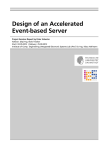
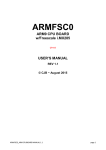
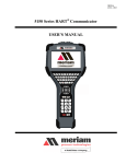
CANflight is delivered with the eXtended CAN Tool (XCT) software, a powerful CAN, ARINC825 and
CANaerospace network toolbox for Linux, MacOS and Windows XP/7. Figure 8.1 shows the main window of
XCT.
Figure 8.1: XCT Main Window
Among other features, XCT contains an ARINC825 Communication Profile reader and editor, realtime data
visualization in raw, ARINC825 and CANaerospace formats, network traffic/error statistics and an interface for
CANaerospace/ARINC825 Periodic Health Status Messages and Node Services. XCT may be used also for
interfacing to end systems corresponding to the ARINC specifications 812 and 826 which are both based on
ARINC825. XCT contains all necessary functions for CAN, CANaerospace and ARINC825 network
compatibility verification, end system testing, CAN network timing analysis and ARINC825 communication
profile generation and analysis. The User's Manual for XCT is contained in the toolbox itself. The current
version for all supported operating systems may be downloaded from:
www.wetzel-technology.com/files/XCT
XCT has a window-oriented interface that communicates with CANflight using an Ethernet/UDP/IP connection.
Multiple instances of XCT may connect to any CANflight channel and control transmission and reception of
CAN messages. XCT configuration files containing application specific settings ("Project") can be generated
and reloaded. XCT project configuration files allow to save and reload XCT configurations and exchange them
with other XCT users.
Document: CANflight_Users_Manual.pdf
Page 22 of 23
© Stock Flight Systems 2011
Project:
Author: M. Stock
Date: 11.10.2011
CANflight
Rev.: 1.1
CANflight
User's Manual
V 1.1
Stock Flight Systems
Schützenweg 8a
82335 Farchach
Germany
9
CANflight Supplier List
Supplier
Contact
Innovative Control
Systems, Inc.
10801 N 24th Ave. Suite 103
Phoenix, AZ 85029
USA
phone: +1-602-861-6984
fax: +1-602-588-9440
e-mail: [email protected]
website: www.icsaero.com
Stock Flight Systems
Schützenweg 8a
82335 Berg/Farchach
Germany
phone: +49-8151-9607-0
fax: +49-8151-9607-30
e-mail: [email protected]
website: www.stockflightsystems.com
Wetzel Technology GmbH
Hermann-Oberth-Straße 11
85640 Putzbrunn
Germany
phone: +49-89-460892-62
fax: +49-89-460892-63
e-mail: [email protected]
website: www.wetzel-technology.com
Reiser Systemtechnik
GmbH
Oberer Lüßbach 31
85335 Berg/Höhenrain
Germany
phone: +49-8171-4373-0
fax: +49-8171-4373-30
e-mail: [email protected]
web: www.reiser-systemtechnik.de
10 ARINC825/CANaerospace Websites
www.arinc.com
www.arinc825.com
www.canaerospace.net
Document: CANflight_Users_Manual.pdf
Page 23 of 23
© Stock Flight Systems 2011
Project:
Author: M. Stock
Date: 11.10.2011
CANflight
Rev.: 1.1