1
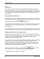
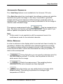
October 2013 Axiocam 105 color Installation + Reference – 10.2013 Carl Zeiss draws the User's attention to the fact that the information and references contained in these documents may be subject to technical modifications, in particular due to the continuous further development of Carl Zeiss's products. The documents enclosed do not contain any warranty by Carl Zeiss with regard to the technical processes described in the documentation or to certain reproduced product characteristics. Furthermore, Carl Zeiss shall not be held liable for any possible printing errors or other inaccuracies in this documentation, unless proof can be furnished that any such errors or inaccuracies are already known by Carl Zeiss or that these are not known to Carl Zeiss due to gross negligence and that furthermore Carl Zeiss has for these reasons refrained from eliminating these errors or inaccuracies appropriately. Carl Zeiss hereby explicitly draws the User's attention to the fact that this manual only contains a general description of the technical processes and information, the implementation of which in any individual case may not be appropriate in the form described here. In cases of doubt, we recommend the User to consult Carl Zeiss. This manual is protected by copyright. Carl Zeiss has reserved all rights to this documentation. It is prohibited to make copies, partial copies, or to translate this manual into any other language, except copies for personal use. Carl Zeiss explicitly draws attention to the fact that the information contained in this manual will be updated regularly in compliance with the technical modifications and supplements carried out in the products and furthermore that this manual only reflects the technical status of Carl Zeiss's products at the time of printing. Microsoft, Windows, and Windows 7 are registered trademarks of Microsoft Corporation in the United States and/or other countries. Carl Zeiss Microscopy GmbH Carl-Zeiss-Promenade 10 07740 Jena, Germany [email protected] www.zeiss.com/microscopy Carl Zeiss Microscopy GmbH Königsallee 9-21 37081 Göttingen, Germany © Carl Zeiss Microscopy GmbH, 2013 Notice from the Producer The referenced Software of Carl Zeiss ("Zeiss Software"), contained in this documentation, was designed, realized, verified, validated and released in a certificated process environment. The quality management system is certified following DIN EN ISO 9001. The fields of application of the Software are common tasks and applications in microscopy and/or imaging (so called "Off-The-Shelf Software"). Though the user acknowledges that in any kind of use the end user of the Software is responsible for the validation of the Software for the end user’s dedicated intent of use considering all requirements of law and standards (e. g. 21 CFR part 11, FDA, MDD etc.). If necessary the end user has to establish, document, implement and maintain a special process to fulfill all the requirements to conform with the valid rules of law and standards. CARL ZEISS DOES NOT WARRANT THAT THIS SOFTWARE IS USABLE FOR SPECIAL PURPOSES OTHER THAN IN THE FIELDS OF APPLICATION DEFINED ABOVE. Safety Refer to the safety notes and instructions in the manuals of all necessary devices (e.g. microscope peripherals, cameras, computers, computer additionals, etc.) before installing and using the software (see also "Safety Notes AxioVision, AxioVision LE, SAP 000000-2054-368"). Disposal and Recycling This product has been developed, tested and manufactured in accordance with the applicable environmental provisions and directives of the European Union. The product and its accessories comply with EU directives 2002/95/EC (RoHS) and 2002/96/EC (WEEE), insofar as these apply to this product. We have implemented a take-back and recycling process that ensures that proper recycling is carried out in accordance with the aforementioned EU directives. Please contact your Carl Zeiss sales/service organization for details relating to disposal and recycling. This product must not be disposed of with domestic waste or using municipal waste disposal services. In the event of resale, the seller must inform the buyer of the need to dispose of the product appropriately. Table of Contents Table of Contents 1. Installation ............................................................................................... 1 1.1 Safety Regulations ........................................................................ 1 General Notes ........................................................................... 3 Backup Copies .......................................................................... 3 1.2 System Requirements ................................................................... 4 Contents of Delivery .................................................................. 4 1.3 Setting up the Camera System ..................................................... 5 Operating the Camera on a PC................................................. 5 Installing the PCIe bus interface card on the PC ................. 5 Connecting the camera to the PC ........................................ 6 Mounting the camera onto the microscope .......................... 7 Function Indicator ...................................................................... 7 Checking the Equipment has been set up correctly.................. 8 1.4 Installing the Driver Software ........................................................ 8 Installing the Camera Driver using the Setup Program............. 8 1.5 Notes on Maintenance ................................................................ 11 Camera Electronic ................................................................... 11 LED Indications ....................................................................... 11 Optical System ........................................................................ 11 Cleaning the Infrared Barrier Filter or Protective Lens ............ 11 Important Note on the Use of C-Mount Objectives ................. 12 2. Image Acquisition ................................................................................. 13 2.1 General ........................................................................................ 13 2.2 Quick Guide to the First Image with AxioVision .......................... 13 The Standard Workflow ........................................................... 14 Step by Step to the First Image ............................................... 15 2.3 Adjust Property Page .................................................................. 21 Exposure ................................................................................. 22 Automatic Exposure ........................................................... 23 White Balance ......................................................................... 23 Color Adjustment ................................................................ 24 Histogram ................................................................................ 25 2.4 Frame Property Page .................................................................. 27 Camera Mode.......................................................................... 27 Frame ...................................................................................... 28 Axiocam 105 color Installation + Reference Guide i Table of Contents 2.5 General Property Page ................................................................ 30 Color Saturation ...................................................................... 30 Image Orientation .................................................................... 31 Shading Correction.................................................................. 31 2.6 Practical notes on Operation in AxioVision ................................. 35 Reset Camera to a Default State ............................................ 35 Notes on Optimum Color Reproduction in AxioVision ............ 37 2.7 Information for Displaying Axiocam Images in AxioVision .......... 38 Recommended Camera Settings ............................................ 40 Recommended Monitor Settings ............................................. 41 2.8 Background Information .............................................................. 41 Gamma Setting ....................................................................... 41 Configurable Toolbars for Operating the Camera ................... 41 3. Trouble Shooting .................................................................................. 42 3.1 Software ...................................................................................... 42 4. Technical Data ...................................................................................... 44 4.1 Axiocam 105 color ....................................................................... 44 ii Printed 10.2013 Installation 1. Installation The Axiocam 105 color is a high-resolution digital camera with a color CMOS sensor and USB 3.0 interface for universal light-microscopy applications. To make it easier for you to set up the camera, please follow the instructions in these chapters step by step. In this manual the interface between the Axiocam 105 color and the computer is called USB 3.0. 1.1 Safety Regulations Please read this chapter carefully and observe the regulations in order to ensure your safety and the intended operation of the system. Please observe the warnings and notes printed in this manual and on the unit. The cameras has been manufactured and tested by Carl Zeiss according to the regulations specified in CE and has left the manufacturer’s premises in perfect working order. In order to ensure that this condition is maintained and to avoid any risks when operating the system, the user must comply with any notes and warnings contained in this manual. Exemption from statutory liability for accidents The manufacturer shall be exempt from statutory liability for accidents should the operator fail to observe the safety regulations. Axiocam 105 color Installation + Reference Guide 1 Installation Limitation of liability No warranty shall be assumed by Carl Zeiss during the warranty period if the equipment is operated without observing the safety regulations. In any such case, Carl Zeiss shall be exempt from statutory liability for accidents resulting from such operation. Exemption from warranty Carl Zeiss shall be exempt from any warranty obligations should the user fail to observe the safety regulations. Carl Zeiss only guarantees the safety, reliability, and performance of the system if the following safety regulations are closely observed. The electrical installations of the room where the system is to be set up must conform to IEC requirements. Warning: Any interruption of the PE conductor, either internally or externally, or removal of the earthed conductor will make the system unsafe to use. Any intentional interruption of the earthed conductor is illegal. Attention: To interrupt the power supply simply disconnect the data cable. Setup, expansions, re-adjustments, alterations, and repairs must only be carried out by persons who have been authorized by Carl Zeiss. Use only those cables supplied by Carl Zeiss. Do not allow any cables to trail across the floor, where they can be snagged by people walking past. 2 Printed 10.2013 Installation General Notes Please ensure the notes described below are adhered to when setting up and operating the camera. All connectors must be firmly and securely attached. Use the screw coupling if possible. Please protect the data cable from excessive heat (e.g. halogen lamps, microscope fluorescence illumination). Only use the camera in a clean and dry location. The camera must be protected against mechanical impact. External damage may affect the operation of inner components. Keep chemicals and fluids away from the camera. To avoid the risk of fire, do not use near inflammable liquids or gases. Make sure there is sufficient ventilation of the camera head. Avoid direct exposure to sunlight and locations near to heat sources (radiators, stoves). Overheating can cause noisy images. The camera housing can be cleaned using normal microscope cleaning material. In case of repair please contact your local Carl Zeiss representation. Backup Copies We strongly recommend that all users save the data they create, such as images, measurement data, archives, reports, forms and documents, at regular intervals on an external medium. Otherwise it cannot be excluded that access to this data may be lost as a result of operational errors or hardware defects. Carl Zeiss accepts no liability for consequential damage resulting from insufficient data protection. Axiocam 105 color Installation + Reference Guide 3 Installation 1.2 System Requirements The appropriate system requirements relating to hard- and software equipment can be found in the file "Installation Guide.PDF" on the actual product DVD. Contents of Delivery Axiocam 105 color USB 3.0 data cable PCI express (PCIe x1) Interface card 4 pin Molex power connector cable 15 pin SATA power connector cable DVD-ROM with device driver and Installation+Reference Guide Power connector cables, PCIe interface card, camera, USB 3.0 cable 4 Printed 10.2013 Installation 1.3 Setting up the Camera System Operating the Camera on a PC Installing the PCIe bus interface card on the PC Static electricity can damage electronic components. To protect electronic components against static electricity, do not touch them until you have grounded yourself to the casing of the device. Never touch the contacts of the electronic components. We also recommend that you work only on an antistatic mat. For installation of the USB 3.0 PCIe interface card, please also take into account the notes in the interface card documentation. Only the basic principles of interface card installation are described in this manual. Molex power connector cable, PCIe interface card, USB 3.0 cable, camera Switch off your PC and all connected peripherals. Disconnect the PC and the peripherals from the mains and open the computer case. Axiocam 105 color Installation + Reference Guide 5 Installation Examine your PC’s power supply to see if it has Molex type connectors or SATA type connectors. Choose the appropriate power connector cable for the following steps. If your PC’s power supply has both connector types, choose only one cable. Connect the appropriate power connector cable to one of the open connectors from your computer’s power supply. Connect the other end of the power connector cable to the PCIe interface card. Insert the PCIe interface card into the appropriate slot on your computer. Close the computer case and reconnect the peripherals. Special details on opening your computer and on the slots it contains can be found in the relevant documentation from your PC’s manufacturer. The provided power connector cables are not necessary if the connectors from your PC’s power supply can extend far enough to connect directly to the PCIe interface card. If it cannot extend far enough and a power connector cable is needed as an extension, use only one of the two provided cables. Connecting the camera to the PC Lay the data cable carefully between the camera and the PC. Make sure that the cable is a safe distance from hot light sources on the microscope, to prevent it being damaged by heat. Connect the supplied USB 3.0 cable to the Axiocam 105 color. Tighten the screws with a screwdriver until it is finger tight. Connect the other end of the USB 3.0 cable to the PCIe interface card. 6 Printed 10.2013 Installation Power is supplied to the Axiocam 105 color via the interface card. If you switch off the PC, the camera is also switched off. During operation the camera may heat up. This is quite safe. Mounting the camera onto the microscope To mount the camera onto your microscope’s TV port, use a C-mount adapter. Suitable adapters (example): 1.0x 0.63x 0.5x Port 44 452995 (44 C2/3") 452997 (44 C2/3") 452998 (44 C1/2”) Port 60 456105 (60 C2/3") 1069-414 (60 C2/3") 1069-415 (60 C1/2”) Port 60N 426114 (60N C2/3") 426113 (60N C2/3") 426112 (60N C2/3") The adapters are not supplied with the camera. To mount the camera onto the microscope, remove the dust cap from the camera’s C-mount port. Screw the adapter in as far as it will go. Then mount the camera onto the microscope’s TV port. Please ensure that no dust enters the opening of the camera or the microscope’s TV port. Never touch the surface of the infrared barrier filter in front of the CMOS sensor with your fingers. If you remove the camera from the microscope, make sure you immediately cover the C-mount opening with the dust cap provided, to prevent dust from getting in. Function Indicator After you have switched on the PC, the LED on the camera will light up red. As a rule, if the LED is red, this indicates that power is being properly supplied to the Axiocam 105 color via the data cable. However the driver has not yet been installed. Axiocam 105 color Installation + Reference Guide 7 Installation For the definitions of the LED color signals, please refer to Notes on Maintenance. Checking the Equipment has been set up correctly Check the following connections: The Axiocam 105 color is mounted onto the microscope and is receiving light. The Axiocam 105 color is connected to the PC via the USB 3.0 data cable. If the LED on the Axiocam 105 color does not turn red now, please check that you have carried out all of the above steps correctly. 1.4 Installing the Driver Software In order to operate the Axiocam 105 color the AxioVision software is needed. First connect the Axiocam 105 color to your PC (see the section "Setting up the Camera System"), and then install the driver software. Installing the Camera Driver using the Setup Program Notes: For installation under Microsoft® Windows 7, you need to log on with administrator privileges. If you do not have access to administrator rights on your computer, please speak to your system administrator. 8 In this section, installation is explained using screenshots from Microsoft Windows 7. Printed 10.2013 Installation If you have inserted a USB 3.0 PCIe interface card, which was not supplied by Carl Zeiss or is supported by Carl Zeiss, into your computer, you first need to install this card with the help of the documentation enclosed by the manufacturer. Depending on your operating system this installation may not be necessary, as the drivers may already be integrated into the operating system. After you have inserted the DVD into the PC’s DVD drive, installation will start automatically. If the automatic start function has been switched off on your system (autorun) you must start the installation program manually in the following way: Double-click on the desktop icon Computer Double-click on the desktop icon Computer Start the Setup.exe or CheckOS.exe program. After the start procedure, (automatically or manually) the installation monitor will be displayed. Start the installation of AxioVision by clicking on . Select the language you want to install: Axiocam 105 color Installation + Reference Guide 9 Installation 10 Printed 10.2013 Installation Click OK and follow the installation wizard. There is no need to activate any special feature during the software installation process. To complete the camera installation, please go to our website to download and run "Installation 01 - Axiocam 105 color": http://www.zeiss.com/axiocam105 1.5 Notes on Maintenance Camera Electronic Camera, interface and power supply are maintenance free. LED Indications Red: Green flash 3x: Green: Off: Power supplied; no driver loaded, camera not detected USB 3.0 connection detected Driver loaded; camera ready No power supplied Optical System The internal optical components of the camera should always be protected. If no lens or TV adapter incorporating optics is screwed into the camera's C-Mount thread, the camera's sensor and IR-filter must be protected by screwing the protective cap onto the camera's C-Mount thread. Cleaning the Infrared Barrier Filter or Protective Lens Contamination of the infrared filter or the protective lens has an adverse effect on the quality of the resulting image (dark points, cloudy structures in the image). If there is dry dust on the front side of the infrared filter, you can remove it with a soft brush or with cotton (wool) after unscrewing the lens or TV adapter. Axiocam 105 color Installation + Reference Guide 11 Installation Important Note on the Use of C-Mount Objectives The camera can be mounted onto microscopes with standard TV-adapters with C-mount connections. Carl Zeiss supplies the camera complete with a pre-mounted infrared barrier filter, which offers the optical advantage for use on microscopes of a lower sensitivity to dust. The IR barrier filter is situated approx. 11 mm behind the outer edge of the C-mount opening in the camera. Due to this pre-mounted IR barrier filter, C-mount objectives that screw more than 11 mm into the thread cannot be screwed into the camera. 12 Printed 10.2013 Image Acquisition 2. Image Acquisition 2.1 General The Axiocam 105 color is a high-resolution digital camera for color images. It has been designed to be used in the field of light microscopy for general observation, routine work, and simple applications in which a sufficient amount of light is available. The camera is particularly well suited for materials microscopy applications or for the acquisition of images of stained or naturally colored microscopic specimens. Because of its small size, the camera is also well suited for environments with limited space. 2.2 Quick Guide to the First Image with AxioVision If you are using several cameras on your system you must always make the Axiocam 105 color camera the active camera before proceeding. Start AxioVision by double-clicking on the corresponding icon. Select from the Acquisition menu the Camera selection Axiocam 105 color function. The image acquisition can also be easily done via the toolbar. Open the corresponding menu by clicking on . The text below describes how to achieve your first image in AxioVision with just a few clicks of the mouse. The Standard workflow is the easiest way to control image acquisition. If the workflows are not displayed, in the View menu select the Windows function, and there select the Workflow command. Axiocam 105 color Installation + Reference Guide 13 Image Acquisition Note: The workbar may in fact be open but covered by the work area. If that is the case, simply click on the Workflow tab at the bottom edge of the work area . The Standard Workflow Live starts and closes the live window. Live properties opens and closes the window for adjusting the display characteristic curve and for controlling the camera (exposure time, white balance etc.). Snap acquires an image using the active camera. Show Properties adapts the image display using a characteristic curve and shows the parameters of the image. Scale bar inserts a scale bar. Draw annotations inserts a caption and scale bar into the acquired image. Navigator opens the Navigator window for zooming. Save saves the image. As the icons are identical on all menus, the following description applies both to operation via the toolbar and to the workflow. 14 Printed 10.2013 Image Acquisition Step by Step to the First Image Select the camera you want from the menu: Acquisition Camera selection Axiocam 105 color camera Set the light path to the camera. Then click on the live image icon. The live window is opened to display the camera image This function can also be called up via the Acquisition Live menu. Now focus the camera image and select the frame you want to acquire. In the footer you can select a suitable scaling for the objective you are using from the List of available scalings. By clicking on this icon, overexposed (too bright) areas will be displayed in red in the live image. Clicking on the gamma icon in the bottom line of the live image accomplishes the optimum color reproduction. This function is disabled for the Axiocam 105 color. With some of the other cameras, you can select the speed of the live image (Slow, Medium, Fast). Axiocam 105 color Installation + Reference Guide 15 Image Acquisition Click on the icon Show live window properties to open the live properties. Here you can see the settings for the display of the image like Brightness, Contrast and Gamma. Settings made here are passed on the acquired image. Note: Only the display is adapted; the camera data remains unchanged. 16 Printed 10.2013 Image Acquisition Make changes for the camera settings on the following controls: The central element is the setting for the exposure time on a digital camera. The Measure button can be used to determine an optimum exposure time. If you are using a color camera, you need to perform a white balance for the image. If you select the automatic balance (Automatic button), the camera tries to determine an optimum value itself. Using the Warmer/Colder slider you can shift the target value of the white balance to warmer ( redder) or colder ( bluer) tones. The Show Channels check box allows you to switch to an alternative setting option if you wish to influence the target value of the white balance manually for each channel. If you are using a color camera, you need to perform a white balance for the image. If you select the automatic balance (Automatic button), the camera tries to determine an optimum value itself. Enter further settings for the selected camera on the Adjust, Frame and General property pages. Click on the camera icon to acquire an individual image, or in the Acquisition menu click on Snap. Axiocam 105 color Installation + Reference Guide 17 Image Acquisition Click on the Properties icon and activate the Display tab. Any changes you make here are displayed in real time in the image window. Move the sliders Gamma Contrast Brightness up or down to adjust the image. Good color reproduction on a monitor is achieved with a gamma value of around 0.45. To find the optimum setting for contrast and brightness, click on Min/Max. To undo all your changes, click on Linear. You can use this icon to insert a scale bar into your image. The appropriate scaling must have been generated and selected in advance. 18 Printed 10.2013 Image Acquisition This icon is used to open the window for generating annotations. Lettering and marking can be inserted in the Draw Annotation(s) window. The other options available in this dialog window are described below. In the dialog window Draw Annotation(s) the icons scalebar, text, line, rectangle, outline, curve und ellipse are available in the menu line. In the dialog window Draw Annotation(s) a field for Settings for selected items as well as for Font are available. If Display tag name is activated, you can use the icon in the drop-down list box Tag. The dialog window Select tagopens where parameters for lettering can be selected. In the Draw Annotation(s) dialog window a number of different zoom symbols and two buttons to toggle the color channels are available at Axiocam 105 color Installation + Reference Guide 19 Image Acquisition the bottom of the image window Using the Navigator you can magnify or reduce the image and position the displayed image area in the overview window. Click on this icon to save the image you have generated to the computer’s hard drive. Notes: Once you have found a good camera setting, you can save it with the Settings Editor in the Tool menu and load it again automatically in the future. This allows you, for example, to acquire particular samples under the same conditions every time. 20 To allow correct scalings to be selected in the footer of the live image during acquisition, you need to have generated these before you start your work. If you are using a motorized or encoded microscope, the scalings can be allocated automatically. For further information, see Chapt. 9 "Configuration" in the AxioVision Manual. Printed 10.2013 Image Acquisition 2.3 Adjust Property Page This property page contains a summary of the most important camera settings, which are constantly used during operation. The property page is split into the fields Exposure, White Balance (with color settings) and Histogram (for the display of an image histogram). Axiocam 105 color Installation + Reference Guide 21 Image Acquisition Exposure The camera’s exposure time can be adjusted to the lighting conditions on the microscope using a slider or by entering an exposure time directly into the input field. When entering the exposure time manually you can state the value range directly using the abbreviations "ms" for milliseconds and "s" for seconds. Exposure time measurement The program assists in calculating an optimum exposure time, at which the camera will be maximally saturated without being overexposed. To perform this calculation, click on the button. The exposure time calculated is available for subsequent images. It can be changed at any time by moving the slider or by entering a new exposure time manually. This measurement function uses all the image information from the camera sensor for the exposure measurement as standard (integral measurement). Weighting of exposure time measurement During an exposure time measurement an attempt is made to expose the camera in such a way that the sensor is not overexposed in any area of the image. The value calculated therefore corresponds to 100% of the camera’s maximum exposure range. The exposure time measurement can also be adjusted to particular lighting conditions. If under certain acquisition conditions the exposure time measurement does not achieve satisfactory exposure of the areas of the image in which you are interested, it is possible to influence the result of this measurement by adjusting the weighting. A setting of 50% means that by pressing the button, 50% of the exposure time is measured and set for actual acquisition. The setting range is between 10% to 200%. 22 Printed 10.2013 Image Acquisition Automatic Exposure The Auto Snap feature is not available for the Axiocam 105 color. If the Auto Live check box is activated, the software continuously sets the exposure during the live image. In this way it is possible to generate images with the correct exposure without having to manually enter an exposure time. The exposure time currently calculated in the live image is used for each individual image. The exposure measurement button can be pressed at any time. The Auto Live function will then be deactivated. This is useful if you want to update the exposure time for a current live image. Note: In this mode it is not possible to edit the exposure times in the multichannel mode for the individual channels. White Balance In order to achieve a color display which is neutral and close to reality it is necessary to balance the individual color channels against one another. This requires a scene without a sample to be set in the microscope. The scene should be white, neutral and illuminated as evenly as possible. It must not be overexposed. : Using this button you can specify a reference point for the white balance yourself. To do this, use the pointer to click on a white area in the live image. : Starts the measurement. The weighting factors calculated for the color channels are then displayed. : Using this button you can switch back to the basic white balance setting. This setting is optimized for a halogen light temperature of 3200 K. Axiocam 105 color Installation + Reference Guide 23 Image Acquisition : Using this button you can switch back to the basic LED white balance setting. This setting is optimized for a LED light temperature of 5500 K. Color Adjustment Using the color sliders you can increase or decrease the proportion of each basic color. Please note that each time a change is made, a proportionate adjustment of the other colors also takes place automatically. The use of the color sliders is recommended in particular for manual adjustment of the white balance in image regions that are completely filled. Here the automatic method can lead to color distortion. In this case also try the 3200 K standard setting as an alternative. Notes: Please note, that the display curve has to be adapted to the gamma value 0.45 in the histogram for a realistic color reproduction. On a microscope, however, the brightness of a halogen lamp is often adjusted by changing the lamp voltage. This changes the color of the light emitted at the same time, though. By moving the slider it is possible to adjust the target color value of the white balance to the color temperature of the halogen illumination. At the middle setting, the color white (R=B=G) is taken as a neutral value. This neutral value can also be achieved at any time by clicking on the Reset button. Alternatively, you can influence the color channels individually by activating Show channels: Clicking on the buttons and allows you to change the weighting of the individual color channels manually. By using this method, the white balance you have generated can be subsequently changed. Each click on the arrows shifts the weighting of the colors in the direction indicated. 24 Printed 10.2013 Image Acquisition These changes can be observed immediately in the live image and in the histogram display. Note: Further information on setting optimum color reproduction in AxioVision can be found in Chapter 2.6 "Practical Notes on Operation in AxioVision" - "Notes on optimum color reproduction in AxioVision". A setting using this method can be saved as a setting with a name of your choice and subsequently reloaded. Activate the corresponding parameters (ex: White Balance Red, White Balance Green, White Balance Blue) in the menu Tools Settings Editor. Histogram A histogram indicates the intensity distribution of the image signal in the live image and the acquired image. It provides a clear representation of the brightness distribution in the current image. The horizontal axis corresponds to the scale of possible intensity values from dark to light and the vertical axis shows the number of pixels calculated from the current image which possess this intensity value on the x axis. With the color camera the value distribution is displayed separately for each color channel in three lines (red, green and blue). If an image is overexposed, at least one curve on the histogram is cut off at the right-hand edge of the display area, where it forms a maximum. Reduce the exposure time or insert gray density filters into the microscope’s beam path to reduce the amount of light. It is also possible to reduce the lamp voltage of the microscope illumination. However, this changes the basic color of the illumination (color temperature) and requires a new white balance. If an image is underexposed, the histogram does not reach the right-hand edge of the display area. As a result, optimum use is not made of the camera’s resolvable gray value range. You should therefore increase the exposure time or the amount of light in the microscope. Axiocam 105 color Installation + Reference Guide 25 Image Acquisition Log: By clicking on this button it is possible to influence the histogram display. You can toggle between a linear scaling and a logarithmic display of the signals represented in the histogram. The logarithmic display makes it possible to view small amplitudes and high peaks at the same time in a single overview. Otherwise, because of the automatic scaling of the display, small signal values are often not visible in the diagram. Skip: This function can be used to influence the automatic scaling of the histogram. If an image contains an extremely bright glare or extremely dark features the result will be overexposure or underexposure of the image in these areas. All of these pixels possess the maximum / minimum numerical value which can be displayed (e.g. in an 8-bit image 255 for overexposure or 0 for underexposure). Consequently, for the gray value 255 the histogram has to display an extremely high number of pixels with the same value. As the scaling of the histogram curves is automatically adjusted to this high value, smaller values can no longer be resolved in the display. By using the Skip function the maximum values at the upper and lower end of the histogram are omitted during the scaling of the display. 26 Printed 10.2013 Image Acquisition 2.4 Frame Property Page The Frame property page can be used to select a frame (ROI) for the image acquisition and is split into the fields Resolution and Frame. Camera Mode RGB and B/W: With the Axiocam 105 color, it is possible to use these setting options to select whether you want the camera to produce a color or a black/white image. This may be useful e.g. to reduce the volume of data or if the sample only contains black/white information. Axiocam 105 color Installation + Reference Guide 27 Image Acquisition The camera will always acquire a color image, and this is then converted to a black/white image. In the drop-down list box underneath you can select from various camera operation modes. With the Axiocam 105 color, three modes are available: in the Color 1x1 mode, the resolution from the camera is set to its highest. In the Color 2x2 and Color 4x4 modes, pixels are combined (in arrays of 2x2 and 4x4 respectively) to represent 1 pixel. While decreasing resolution, these modes increase the camera’s light sensitivity, which is useful for darker samples. Frame In this field you can specify whether the frame or the entire area of the sensor is used for the acquisition. Refresh overview: This button makes it possible to insert an overview image into the area where the frame can be positioned. This makes it extremely easy to target your specific area of interest. In the displayed overview image a frame can be positioned by using the mouse, which corresponds to the selected frame of the acquired image. The shape and size of the frame can be changed by clicking on and dragging the edges of the frame while holding down the left-hand mouse button. It is also possible to move the frame by clicking inside it and keeping the button pressed as you change its position. Center: By clicking on Center you can automatically center the selected frame. This can be useful as interesting parts of the sample are usually moved to the center of the view area. In addition the center of the view area is the place of the highest optical quality. Framestart / Framesize: The start point and the selected frame size will be displayed in these input fields. Alternatively you can enter the values manually. It is also possible to select default frame sizes from the drop-down list box and position it in the center of the image by using the Center button. 28 Printed 10.2013 Image Acquisition Memory used: Memory used shows the memory size of the acquired image, which depends on the camera resolution, the image size of the selected image frame and of the selected gray value scaling. The following table provides an overview: Axiocam 105 color Image size 2560 x 1920 1280 x 960 640 x 480 8-bit 14.2 MB 3.6 MB 1 MB In AxioVision, all acquired images can be saved in ZVI image format. When images are exported into other image formats (TIF, BMP, JPG etc.), this option is not available. With these image formats the image data is converted in accordance with the display characteristic curve that has been set. Axiocam 105 color Installation + Reference Guide 29 Image Acquisition 2.5 General Property Page On this property page you enter the basic settings for the camera. Color Saturation The slider for saturation can be used to increase or reduce the intensity of the color impression. The default setting is 0. 30 Printed 10.2013 Image Acquisition Note: Please note that a gamma setting of 0.45 is required for correct color reproduction. This can be achieved in the Live image by activating the button. Only the display is influenced by this function. The data remain unchanged. Image Orientation An Axiocam 105 color image is adjusted in such a way that the image orientation corresponds to the image in the eyepiece when mounted on an upright microscope with the front of the camera facing you. Setting options: Original Vertically reflected Horizontally reflected Rotated 180 degrees This starting position can be adapted via this menu to suit your requirements. If, for example, the camera’s cable routing needs to be changed on an inverse microscope, the camera can be mounted at a different angle, without the correspondence between the image orientation and the eyepiece being lost. Note: Activating an image rotation can reduce the maximum live-image speed. Shading Correction Activate this function if you notice, e.g. with brightfield images, a reduction in image brightness at the image edge or uneven color representation. For this calibration process make sure that the camera is viewing a completely empty image. To ensure that this is the case, move your sample on the microscope completely out of the field of view. Axiocam 105 color Installation + Reference Guide 31 Image Acquisition Shading correction to improve image quality In microscopy, numerous side effects can have an undesirable influence on image quality. Dust and particles in the beam path, for example, can leave dark spots in the image, and, under certain conditions, diaphragms and optics can cause slight shadowing that increases towards the image edge, due to unavoidable physical effects. For all Axiocam models it is possible to acquire a shading reference image and apply this automatically each time an image is acquired. On the camera property page General you will find the Shading Correction button. This can be used to trigger the acquisition and saving of a shading reference image. If you are using a motorized microscope or a microscope with an encoded nosepiece, it is possible to acquire a separate reference image for each objective. These images are then applied automatically for the objective that has been selected. Procedure for generating objective-specific shading correction Prerequisites: Encoded or motorized microscope stand. Camera belonging to the Axiocam family. The following steps are required to set and apply shading correction in the optimum manner: Activate the Automatic check box on the camera property page General. Make sure that all motorized and encoded microscope components are correctly configured in the Micro Toolbox. For the automatic application of shading correction, the correct configuration of the available objectives and the cameras is particularly important (please also refer to the MTB2004 Configuration manual). Set the light intensity with which you want to work. 32 Printed 10.2013 Image Acquisition To do this, set a suitable exposure time and the white balance of the camera. Set Köhler illumination on the microscope (if using transmitted light) in order to create a reproducible image-acquisition situation. Create a test image of a specimen with quality that is as high as possible. Check the quality of the Köhler setting for each objective with which you want to generate automatic shading correction. Now move the sample out of the camera’s field of view and bring the microscope clearly out of focus. Generate a shading reference image for each objective, one after the other, by clicking on the Shading Correction button on the camera property page General. If you are using a fully motorized microscope, it is very easy to save and reload the configuration of the light path setting in a hardware setting: Light intensity Gray density filter Setting of the condenser aperture diaphragm and field diaphragm You can now refocus the microscope and work with the automatic shading correction. Notes: The reference images generated are saved on a user-specific basis. All users who have their own login must therefore generate their own set of reference images. Automatic shading correction only takes into account the changing of the objective. Changes to the settings of other optical components, such as an Optovar, the camera adapter or the condenser, are not taken into account and will make it necessary to repeat the generation of the reference images. Axiocam 105 color Installation + Reference Guide 33 Image Acquisition If several cameras are operated on a system (e.g. an AxioCam MRm and an AxioCam IC), the reference images for each camera will be managed separately. In the Multidimensional Acquisition function, a function for fluorescence-channel-specific shading correction is offered under Extended parameters on the C (Channel) property page. Activating shading correction can reduce the maximum possible speed of the live image. Applying object-specific shading correction Activate the Automatic check box on the camera property page General. Note: Make sure that the shading reference images generated are still having the desired effect if the images were generated some time ago. They will need to be generated again in any case if the optical settings of the microscope have been changed. This applies to the following settings in particular: Lamp adjustment Köhler setting Optovar Camera adapter Camera port Applying shading correction manually With non-motorized and non-encoded microscopes the automatic shading correction cannot be activated. But it is possible to carry out shading correction using a previously generated standard reference image. This image is applied irrespective of the objective set. 34 Printed 10.2013 Image Acquisition To generate this file, follow the procedure described above. However, this function can only be carried out for one objective. As a compromise for all available objectives, you can perform this using an objective with a medium magnification. For special requirements you will need to carry out shading correction again, specifically for the objective you are using, prior to the acquisition of an image. Shading correction via image processing For advanced users it is also possible to carry out shading correction via an image processing function. On the Processing menu Adjust Shading Correction you will find a function that allows you to perform targeted subsequent processing. This function can be used in a script to allow you, for example, to generate and apply an image with an assigned shading correction for each objective. 2.6 Practical notes on Operation in AxioVision In the following sections you will find a number of practical tips on resetting the camera to a predefined default state, on the speed of the live image and on optimum color reproduction. You will also find information on various background information and details on configuring toolbars. Reset Camera to a Default State To reset the numerous camera parameters to a reproducible default state, reset functions are available. In the AxioVision menu Acquisition you will find the Status function. If you click on the Reset button in the Status dialog window, the following settings of the active camera are reset: Axiocam 105 color Installation + Reference Guide 35 Image Acquisition Camera parameters for all cameras (as available): Exposure time White balance Auto Live Sensitivity Range Frame (ROI) Image Orientation Shading Correction USM HDR Color Saturation Binning 20 ms 3200 K Off 100% Full frame No changes Off Off Off No changes 1x1 (sensor basic resolution) With the function Load Factory Defaults (context menu of the live image) you can reset camera settings in addition to the settings for the live display: Spot Meter / Focus Bar Spot Meter Auto Best Fit Auto Min/Max Display Curve Gamma White balance Overexposure Zoom Ruler Cross Bar Live Staus bar Close after Snap 36 No changes No changes Off (in case of color cameras), No changes (in case of b/w cameras) Off (in case of color cameras), No changes (in case of b/w cameras) Full range 0.45 (in case of color cameras), Linear (in case of b/w cameras) No changes (supplied in the driver) Off Fit into window No changes No changes No changes No changes Printed 10.2013 Image Acquisition Notes on Optimum Color Reproduction in AxioVision Below you will find a detailed description of how best to set up AxioVision to achieve optimum color reproduction with the Axiocam 105 color. Note: For an optimum color reproduction the monitor first has to be adjusted. To do so please use a well-suited image. Adjusting the display characteristic curve in AxioVision In order to achieve optimum reproduction of color images of the Axiocam 105 color on a monitor, the display characteristic curve must be used to set "gamma compensation". The advantage here is that only the display is influenced and the actual data will remain unchanged. Further details on this can be found below. The settings can be done as follows: With the mouse click on the icon in the footer of the live image. This adjusts the display characteristic curve automatically for an optimum color reproduction of the monitor (gamma = 0.45). Or in an already acquired image: In the Properties dialog window, set the gamma characteristic curve in the histogram image on the Display property page. Note: This also influences the reproduction of the color saturation. Clicking on this icon returns to a linear display of the data. Axiocam 105 color Installation + Reference Guide 37 Image Acquisition 2.7 Information for Displaying Axiocam Images in AxioVision So that intelligent use can be made of this feature, in AxioVision it is possible to influence the display using the characteristic curve. To do this, right-click in the image acquired and select from the context menu the Properties function. The dialog window Properties is displayed on the screen: 38 Printed 10.2013 Image Acquisition You can now select the area to be displayed by dragging the black rectangles along the characteristic curve or carry out automatic optimization by clicking on the corresponding buttons. A histogram of the gray and color values will be displayed which makes the gray and color distribution visible. The Best Fit, Min/Max and Linear buttons can be used to quickly adjust the histogram display. You can influence the display by clicking on the Log or Skip buttons. Best Fit calculates in the current histogram the values which exclude 1‰ of the pixels contained in the image. The gray/color range calculated in this way is displayed on the screen. (You can adjust the value of 1‰ to suit your requirements). Min/Max displays on the screen the smallest and largest gray or color value present in the image. Linear displays on the screen the total possible value range. Log displays the histogram in a logarithmic scaling, allowing you to effectively evaluate histograms of images with high dynamics. Skip: By using the Skip function the maximum values at the upper and lower end of the histogram are omitted during the scaling of the display. The , and sliders can be used to change the brightness, contrast and gamma of the display. This can also be achieved by dragging the individual "handles" of the characteristic curve in the histogram. You can adjust the brightness and contrast by changing the left or right-hand end points of the characteristic curve individually or by shifting the entire line using the center "handle". The gamma value can be changed by shifting both "handles". Click the Save button to store the current settings. You can use these settings when displaying another image by clicking the Restore button. This enables you to compare different images. Axiocam 105 color Installation + Reference Guide 39 Image Acquisition If you activate the Apply to all T check box the settings in all the acquired instants of exposure are applied to the relevant channel. Note: You can get the best display of colored objects, if the gamma setting is in the range of approx. 0.45. Recommended Camera Settings The standard setting installed for 3200 K (3200 K button on the Adjust property page) often offers the camera the most natural reproduction of the image situation on the microscope. Here the image background is reproduced as it appears on the microscope. This setting is also useful in acquisition situations where no neutral-tint area is available to carry out a balance manually. If the image background in the acquired image is to be displayed with a neutral tint (gray or white), a manual white balance is required. Click on the Automatic button in the White Balance field. If the lamp voltage selected on the microscope is too low, the color of the image background may have been shifted a long way into the red. If a white balance is carried out in this event, the result may be visible deviations in the display of the color of the current sample. Correct this situation by increasing the lamp voltage to achieve a more neutral background, and insert gray filters into the microscope’s illumination beam path to adjust the intensity. The values calculated using the automatic white balance function can be optimized further with the help of manual settings. 40 Printed 10.2013 Image Acquisition Now save this white balance setting together with the current lamp voltage and filter position on the microscope (if available as an adjustable variable) as an AxioVision hardware setting. This will enable you to achieve reproducible settings for color reproduction. Details on working with hardware settings can be found under this keyword in the AxioVision online help. Recommended Monitor Settings The output medium has a significant influence on color perception! Use a familiar specimen to adjust the brightness and contrast rendering. If possible also set the color temperature of the monitor to approx. 5000 K or 6500 K. 2.8 Background Information Gamma Setting This setting is required to compensate for the inherently non-linear behavior of the image tube ("gamma"). It also influences the quality of the color display. You can get the best display of colored objects, if the gamma setting is in the range of approx. 0.45. Many video cameras have built-in gamma compensation, as they are intended for use on video monitors. Configurable Toolbars for Operating the Camera AxioVision allows you to configure your own toolbars. This means that the procedure can be tailored to your own requirements, and thus optimized. The size of the toolbar buttons can also be adjusted, helping you to work quickly with the mouse. A detailed description of how to create toolbars can be found in Chapt. 9 "Configuration" - "Adapting Toolbars" in the AxioVision Manual. Axiocam 105 color Installation + Reference Guide 41 Trouble Shooting 3. Trouble Shooting If errors occur, check first the setup instructions of the camera. 3.1 Software Please also pay attention to all the comments in the file ReadMe.TXT, which is displayed during the driver installation. Axiocam 105 color does not appear in the menu of selectable cameras 42 Make sure that the Axiocam 105 color files have been installed in accordance with the installation of the software. No camera image on your screen Check the light setting of the microscope. Is the green control light on the camera on? If not, check the cable connections between camera and computer. Execute a reset of the camera. Execute an automatic exposure measurement (Autoexposure). Check display adjustments for the live image Check the aperture diaphragm of the microscope. Check the position of the beam splitter between the ocular and the TV port. Check the Event log to see that the camera is indeed provided by Carl Zeiss. . Printed 10.2013 Trouble Shooting The color does not correspond to the impression through the ocular Check white balance and, if necessary, repeat white balance. Check the monitor’s color temperature setting. If necessary, reduce this to the lowest value that can be set (usually 5200 K). Check whether the gamma curve 0.45 function is activated. To do this, open the Properties window. The performance of the camera is not consistent or is too slow Generally the performance of the camera is dependent on the performance of the PC. Make sure the PC hardware and setup are optimal for large data transfers. Check that the camera is connected to the provided USB 3.0 interface card (and not a USB 1 or USB 2 port) on the PC. Make sure no other devices are plugged into the USB 3.0 interface card. Try plugging the camera into a USB 3.0 port that is farther from the PC’s motherboard. Try plugging the USB 3.0 interface card into a slot that is not directly next to the Graphics card slot. Disable "USB selective suspend setting" under Start >Control Panel >Power Options >Change plan settings (for whichever is your active plan) >Change advanced power settings. Axiocam 105 color Installation + Reference Guide 43 Technical Data 4. Technical Data 4.1 Axiocam 105 color Including AxioVision LE64, USB 3.0 connecting cable, USB 3.0 PCIe interface card, Power connector cables Sensor type Aptina CMOS color sensor Number of pixels 2560 (H) x 1920 (V) = 5 megapixels Pixel size 2.2 µm x 2.2 µm Chip size 5.70 x 4.28 mm, corresponds to 1/2.5" Live image frame rates HxV Frame rate at 1ms (maximal values when using optimal hardware) 2560 x 1920 15 fps 1920 x 1080 33 fps Sensor subarea readout (ROI) Free adjustable Digitization 3 x 8 bit / pixel Exposure times 100 us up to 2 s Interface (camera) USB 3.0 Micro-B Interface (PC / card) USB 3.0 Standard A Optical interface C-Mount adapter Dimensions in mm (H x W x D) 29 x 29 x 47.6 Operating systems Microsoft® Windows 7 x64 Ultimate SP1 Certificate CE, FCC Class B, RoHS Power supply Via USB 3.0 interface Environment conditions 0° ... + 50° Celsius, max. 80% relative air humidity, no condensation, free air circulation required Order number 426555-0000-000 Computer hardware, operating system and application software may decrease the frame rates. Selecting a part of the sensor area can increase the frame rate. All specifications are subject to change without notice. 44 Printed 10.2013 Technical Data Axiocam 105 color Installation + Reference Guide 45