1
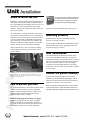
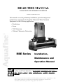
READ THIS MANUAL
PLEASE KEEP FOR PERMANENT REFERENCE
Part No. 115-2, Revised 1-17-03
This manual covers the preliminary installation, operation and general
maintenance requirements for Aquafine Ultraviolet Water Treatment
Equipment for the following applications:
• Disinfection
• Ozone
• TOC Reduction
• Chlorine/Chloramine Destruction
RBE Series
Installation,
Maintenance and
Operation Manual
It is imperative that those responsible for the installation of this equipment,
as well as operating personnel, read this manual and carefully follow all
UIPMENT OPERA
T ORS AND INST
ALLinstructions and guidelines. EQ
EQUIPMENT
OPERAT
INSTALLERS MUST COMPL
Y WITH OPERA
TION
AL SAFETY REQ
UIRECOMPLY
OPERATION
TIONAL
REQUIREMENTS.
Aquafine Corporation builds the finest quality ultraviolet equipment in the
world. When properly installed and operated, Aquafine ultraviolet
tre atment units will provide many years of service.
2
Installation and Operational Safety ................. 3
Description of Equipment
RBE Series ............................................................ 4
Warranty Information ....................................4-5
Refer to this nameplate sticker on your
unit when ordering parts or service.
Unit Installation
Where to Install the Unit ....................................... 6
How to Protect Your Unit ..................................... 6
Hot Water Sanitization .......................................... 6
Operating Pressure ............................................... 6
Removing the Plastic Dowel(s) ............................ 6
Intermittent Operating Requirements .................... 6
Special Requirements for Ultrapure Water ........... 7
Wiring the Unit ...................................................... 7
Installing the Quartz Sleeves
SE, DE and HT units ............................................ 8-9
USD-RBE Series units only ................................... 10
Installing the UV Lamps
Single-Ended (SE) Lamp Design ............................ 11
Double-Ended(DE) Lamp Design ......................... 12
High-Temperature (HT) Unit Design ..................... 13
USD-RBE Series units only ................................... 14
Powering Up the Ultraviolet (UV) Unit ........ 15
Monitoring Devices
UV Lamp Operational Display Panel ................. 16
Running Time Meter ........................................... 16
S-254 UV Optical Sensor ................................... 17
Setting The UV Monitor ......................................... 17
Alarm Contacts ....................................................... 17
Sensor Alarm .......................................................... 17
4-20 mA Sensor Signal Option ............................ 18
Temperature Safety Control Option .................... 18
Lamp Out Alert Indicator Option ........................ 18
Troubleshooting ............................................... 19
Maintenance Requirements ........................... 20
Cleaning the Unit ................................................ 20
LED Display Panel ............................................. 20
UV Lamp Replacement ...................................... 20
Quartz Sleeve Cleaning and Replacement .......... 20
Cleaning the Sensor Probe Window ............... 20-21
Measuring Performance, Sampling ..................... 21
Ballast Replacement ........................................... 22
Parts List ...................................................... 23-26
Electrical Diagram,
General Assembly Drawing and
Warranty Registration Card .......... Back Pocket
3
Safety requirements for
UV equipment
The following safety requirements
relate directly to operator safety. Please
review with all appropriate personnel to
ensure continuous compliance.
These safety requirements are
MANDATORY. Failure to carefully follow
these requirements can cause injury to
the operator and damage the UV unit.
1.
Release the pressure in the UV treatment chamber
before attempting to remove the protective covers
and sealing items.
2.
Disconnect all power to the UV unit before servicing. The unit operates on high voltage and should
only be serviced by qualified personnel.
3.
4.
Do not look at the lighted blue ultraviolet lamps. Do
not operate the ultraviolet lamps outside of the UV
treatment chamber. Exposure can severely
burn and damage eyes and skin.
Supply the unit with the correct voltage and
frequency as indicated on the nameplate decal,
ensuring the unit is wired in accordance with local
electrical codes.
5.
Properly ground the unit. Failure to comply may
result in severe or fatal electrical shock.
6.
Install the unit away from undue vibration that can
damage the electrical components and UV lamps.
7.
Ensure all water connections (flanges and compression nuts) are tightly sealed before applying
pressure to the UV unit. Do not stand in a direct
line with the endplate when inspecting for water
leaks; observe from the front or back.
This “Safety Issue” icon marks
all items relating to safety
issues. Please read and adhere
to these comments carefully.
8.
Do not allow the unit to overheat by operating
without water flow. Normal operating temperature for
standard UV units is 50° to 100°F (10°- 38°C).
For high-temperature units, normal operating
temperature is 50° to 150°F (10°- 66°C).
9.
If the inlet water temperature exceeds 100°F (38°C),
contact the factory for assistance.
10. Do not allow the water temperature to drop below
35°F (2°C).
11. Do not allow the flow rate to exceed the maximum
rated capacity.
12. DO NOT ELECTRICALLY CYCLE THE UV UNIT
MORE THAN THREE (3) ON/OFF CYCLES IN AN
24-HOUR PERIOD.
13. Before start up, flush the UV unit and discharge
piping to rinse out any debris left from installation.
DO NOT LOOK
AT UV LIGHT
4
RBE series
treatment chamber
The models in this series contain all electrical components in a Remote Electrical Enclosure. This is ideal for
applications where the treatment chamber is outdoors or
subject to washdown, etc. All electrical service and
instrument monitoring can be done at the remote site.
The UV treatment chamber is comprised of one or more
multi-lamp cylinders. On either end are gasketed end
plates which contain the stainless steel nipples and the
lamp socket retainer assemblies.
The Remote Electrical Enclosure contains various
electrical components, circuit boards, and all
instrumentation. It is connected to the treatment
chamber via a flexible, watertight electrical cable.
To maintain your UV units warranty, please complete and
return the Warranty Registration Card located in the
back pocket of this manual.
The following installation and operating conditions are
considered hazardous or damaging to the equipment and
can compromise the ability of the Aquafine unit to
perform as intended.
ANY OF THE FOLLOWING CONDITIONS WILL VOID
THE EQUIPMENTWARRANTY:
1.
Failure to connect proper electrical service to unit.
2.
Failure to properly ground the unit.
3.
Failure to eliminate excessive vibration, piping
movement, or water hammer.
4.
Failure to exercise caution in the handling of the
sensitive and delicate components (such as lamps,
Inside each cylinder is a helical baffle that prevents
laminar flow and maximizes the unit’s performance.
The quartz sleeves fit inside the UV treatment chamber
through the holes in the helical baffle. The lamps fit
inside the quartz sleeves. The lamp sockets connect to
the lamps, providing a waterproof seal and a vibrationproof grip. The socket covers on either end of the
chamber protect the lamp sockets and lamp socket
assemblies.
quartz sleeves, electronic boards, etc.) during
installation and/or maintenance procedures.
5.
Failure to avoid excessive stops and starts. Not more
than three (3) on/off cycles per 24 hours of operation.
6.
Operation of visibly damaged equipment.
7.
Failure to avoid undue overhead piping stress
which can result in structural damage to the UV
unit. Limit the load to 50 lbs (22.7 kg) per flange.
8.
Use of components other than those provided or
authorized by Aquafine.
9.
Failure to correct overhead piping connection leaks
or compression nut seal leaks which result in
damage to the electrical components.
10. Operating the unit without water flow.
5
more
WARRANTY
Aquafine equipment is guaranteed to be free from
defects in materials and workmanship (excluding
ultraviolet lamps) for a period of one year from the
date of purchase. Any part suspected of being
defective should be returned prepaid to Aquafine
Corporation. If upon our inspection, the part(s)
proves to be defective, it will be replaced or repaired
(our option) and returned to sender prepaid.
Before returning any par t, contact Aquafine
Corporation for return authorization and shipping
instructions. This guarantee is void if the equipment
has not been installed and maintained in accordance
with instructions. This guarantee is in lieu of all other
warranties, expressed or implied.
To keep your warranty valid and to ensure peak
performance, fill out and return your warranty
registration card (located in the back pocket of
this manual) and use only genuine Aquafine
replacement parts.
6
where to install the unit
Install the UV treatment unit in a horizontal position in a
sheltered area with ample ventilation. Ambient temperatures surrounding the unit should be between 35oF (2oC)
and 110oF (43oC). For operation below 50oF contact
Aquafine. Should your requirements differ, contact the
factory for assistance.
As an ultraviolet UV treatment unit does not introduce
any chemical residue within the water, it is desirable to
install the unit as close as possible to the point-of-use in
order to avoid potential recontamination by discharge
pipes, fittings, etc. The base of the UV treatment unit
should be mounted on suitable support to avoid undue
strain on the unit or your related pipes and fittings.
Allow sufficient service access clearance. In making
your plumbing connections, provide unions, valves,
bypass and drain.
A parts check list was included when this unit
was shipped. Please refer to this list and note
that some parts are small and can be easily
overlooked when discarding packaging.
pressure may rupture and fracture the quartz sleeves.
operating pressure
Standard units are rated for a maximum operating
pressure of 120 psig (8.24 bar).
If your unit has the High Pressure Modification option
(model number suffix “HP”) operating pressure may
increase to 150 psig (10.34 bar).
heat Sanatization
For heat sanitization (temperatures exceeding 170°F
(77°C) up to a maximum of 194°F (90°C)), it is recommended that stainless steel compression nuts be used in
place of CPVC compression nuts. During heat sanitization the S-254 probe must be removed. (Adaptor
available for maintaining Hydrostatic seal during
sanitization.) The selection of the elastomers should
be considered.
Depending on the size of the lamp being used, please allow at
least 36 inches (92 cm) of clearance for 30-inch units or 72
inches (182 cm) of clearance for 60-inch units on the lampchanging end of the unit.
how to protect your unit
The location should be free from undue vibration which
could be caused by proximity to heavy equipment,
erratic or improper pumps. Excessive vibration will
damage internal electrical components and cause
premature failure of the UV lamps.
Limit overhead piping load to 50 lbs (22.7 kg) per
flange. If your piping system is subject to impulse
pressure resulting in a “water hammer” condition, a
surge tank or other means must be provided to remove
this condition, otherwise the extreme momentary
remove the plastic dowel(s)
A plastic dowel is placed inside the UV treatment
chamber to secure the baffle during shipping. The 30”
units have one dowel on the left side only and the 60”
units have two dowels -- one on each side.
Remove the compression nut in the twelve o’clock position
on the left side of the UV treatment chamber. Remove and
discard the plastic dowel. Replace the compression nut. You
7
more
can then proceed with the installation of the quartz sleeves.
wiring the unit
intermittent operation
Connect the liquid-tight flex conduit, which contains
the interconnecting wiring harness, into the remote electrical
enclosure through the liquid-tight connector which is
provided. Connect the wiring harness to the terminal block
starting with terminal block assembly A through terminal
block assembly B. (See Wiring Diagram in back pocket of
this manual.) Optional equipment connections are made on
terminal C. Terminal C blocks are included with optional
equipment.
Never operate the unit without water flow. Permanent
damage is caused to the UV lamps, electronic ballasts
and related components without water flow.
Operating the ultraviolet unit without water flow
through the chamber automatically voids the warranty.
If operated without water flow, the fluid within the
ultraviolet chamber will become hot causing the UV
lamps to lose effectiveness. The heat can permanently
damage the ultraviolet lamps, UV sensor, the lamp ballast
components and related instrumentation.
Should the unit be used for specific batch flow operations, it can be turned “On” and “Off” manually. Make
sure the unit is allowed to warm up for at least one
minute before use, and make sure the unit is turned
“Off” after each session. Do not exceed 3 on/off cycles
per 24 hour operation.
If you need help to determine the best method of operating your UV treatment unit under intermittent conditions,
contact your local representative or the factory.
An optional Temperature Safety Control Device is available
to prevent the overheating problems described above.
special piping requirements
for users of ultrapure water
Ultrapure water users have reported that over time,
exposure to ultraviolet light may photochemically
degrade nonmetallic piping materials, including most or
all fluoro-polymers, resulting in material breakdown
and/or structural failure.
Should your water application and piping material be so
classified, we recommend you install “UV light traps” to
isolate any such susceptible material from direct
exposure to the ultraviolet light. Install the UV light trap
to the inlet/outlet of the UV treatment chamber prior to
the connection of any nonmetallic materials. UV light
traps protect nonmetallic piping. Should you require any
additional assistance, please contact your local
Aquafine representative or the factory directly.
Bring your incoming wiring to the 1/2-inch electrical knockout in the bottom of the remote electrical enclosure. Make
connections to terminal blocks G, N and L. Terminal block L
is “hot”; N is “neutral”; and G is the “ground”. Make sure
your electrical service matches the specifications on the
electrical name plate decal on your unit. Locate an “on/off”
switch near the unit so the current may be turned off for
servicing.
GROUNDING
IT IS IMPERATIVE THAT THE UNIT BE PROPERLY
GROUNDED FOR SAFE AND PROPER OPERATION.
Failure to properly ground the UV treatment unit automatically voids all equipment warranty.
UV performance is line voltage sensitive. Line voltage
should be +5% of rating shown on the electrical nameplate
decal. Voltage outside these limits can reduce the performance of the UV equipment.
8
The procedures on this and the following page apply to
Double-Ended (DE), Single-Ended (SE) and High Temperature (HT) RBE units.
quartz sleeve installation
procedures for new equipment
The quartz sleeves designed for this unit are open
on both ends. For first time unit installations, follow these
quartz sleeve installation procedures:
Remove socket covers
1. Turn off all power to the unit.
2. Wear clean cotton gloves to prevent contamination of
the quartz sleeves.
3. Carefully remove each quartz sleeve from the factory
packaging. Handle these with care as they are fragile.
4. Visually inspect all quartz sleeves for cracks or other
damage. Do not install damaged quartz sleeves.
Place end of quartz sleeve into threaded nipple
5. Remove the socket covers on the ends of the treatment chamber.
6. For High-Temperature units, remove the alignment plate
from both ends of the unit.
7. Remove all compression nuts and any packaging
material from the end plate (if installed).
8. Place the end of the quartz sleeve into the threaded
nipple and slowly push the sleeve into the chamber
through to the second end plate. Repeat for all quartz
sleeves.
Compression nut assembled on the quartz sleeve
9. Install the compression nut and o-ring by placing the oring into the internal relief of the compression nut below
the threaded area. The o-ring should fit into the compression nut.
10. Place the compression nut and o-ring onto the end of the
quartz sleeve until the end of the quartz sleeve touches
the end of the compression nut. Some pushing and
twisting may be required. Deionized water may be used
as a lubricant.
11. Tighten the compression nut approximately 1/2 turn after
the threaded nipple and o-ring make contact.
12. Repeat this procedure for the second endplate.
Rotate compression nut clockwise onto the
threaded stainless nippled end plate with
compression nut tool
Over tightening can break the
quartz sleeves or create leaks.
13. Slowly pressurize the system and fill the chamber with
water to check for leaks.
14. If there are leaks in any compression nut assembly,
depressurize the system and use the compression nut tool
to slightly tighten the leaking compression nut assembly.
15. Retest until a leak-free installation is verified.
16. You are now ready to install the UV lamps.
9
more
quartz sleeve replacement procedures
for existing equipment
The quartz sleeves designed for this unit are open on both ends. For
existing equipment, replace the quartz sleeves as follows:
1. Turn off all power to the unit.
2. Depressurize the system and drain the UV unit.
3. Remove the socket covers on the ends of the
treatment chamber.
Remove socket covers
4. For High-Temperature units, remove the alignment plate from both
ends of the unit.
5. Remove the existing lamp sockets and compression nuts from
the endplate.
6. Wear clean cotton gloves to prevent contamination of the quartz
sleeves and UV lamps.
7. Remove the existing UV lamps.
8. Remove the existing quartz sleeves.
Place end of quartz sleeve into threaded nipple
9. Carefully remove each new quartz sleeve from the factory packaging. Handle these with care as they are fragile.
10. Visually inspect all quartz sleeves for cracks or other damage. Do
not install damaged quartz sleeves.
11. Place the end of the quartz sleeve into the threaded nipple and
slowly push the sleeve into the chamber through to the second
endplate. Repeat for all quartz sleeves.
12. Install the compression nut and o-ring by placing the o-ring into the
internal relief of the compression nut below the threaded area. The
o-ring should fit into the compression nut.
Compression Nut assembled on the Quartz Sleeve
13. Place the compression nut and o-ring onto the end of the quartz
sleeve until the end of the quartz sleeve touches the end of the
compression nut. Some pushing and twisting may be required.
Deionized water may be used as a lubricant.
14. Tighten the compression nut approximately 1/2 turn after the
threaded nipple and o-ring make contact.
15. Repeat this procedure for the second endplate.
16. Slowly repressurize the system and fill the treatment chamber with
water to check for leaks.
17. If there are leaks in any compression nut assembly, depressurize the
system and use the compression nut tool to slightly tighten the
leaking compression nut assembly.
18. Retest until a leak-free installation is verified.
19. You are now ready to install the UV lamps.
Rotate Compression Nut clockwise onto the
threaded stainless nippled end plate with
Compression Nut tool
Over tightening can break the
quartz sleeves or create leaks.
10
USD-RBE Series units only
The quartz sleeves for this unit utilize a design that is open on one end and
closed on the other end. The closed end of the tube is inserted into the threaded
nipple and then through the baffle system in the chamber. Within the baffle,
Teflon bushings provide additional support to the quartz sleeves.
Q U AR
TZ SLEEVE INST
ALLA
TION PR
OCEDURES
ARTZ
INSTALLA
ALLATION
PROCEDURES
For first time unit installations, follow these quartz sleeve
installation procedures:
1. Turn off all power to the unit.
2. Wear clean cotton gloves to prevent contamination of the quartz sleeves.
Stainless socket & lamp end cover design
3. Carefully remove each quartz sleeve from the factory packaging.
Handle these with care as they are fragile.
4. Visually inspect all quartz sleeves for cracks or other damage. Do not
install damaged quartz sleeves.
5. Remove the socket covers on the ends of the treatment chamber.
6. Remove all compression nuts and any packaging material from the end
plate (if installed).
7. Place the closed end of the quartz sleeve into the threaded nipple and
slowly push the sleeve into the chamber. Some resistance may be felt
from the Teflon bushing.
Quartz sleeve installation
8. Install the compression nut and o-ring by placing the o-ring into the
internal relief of the compression nut below the threaded area.
The o-ring should fit into the compression nut.
9. Place the compression nut and o-ring onto the end of the quartz sleeve until the
end of the quartz sleeve touches the end of the compression nut and hand
tighten until snug. Deionized water may be used as a lubricant.
10. Tighten the compression nut approximately 1/2 turn after the threaded
nipple and o-ring make contact.
11. Repeat this procedure for all quartz sleeves.
12. Slowly pressurize the system and fill the chamber with water to check for leaks.
Compression nut assembled on the quartz sleeve
13. When applicable, bleed the air from the UV treatment chamber by opening
the plug on top of the chamber. Replace with a suitable valve.
14. If there are leaks in any compression nut assembly, depressurize the system
and use the compression nut tool to slightly tighten the leaking compression nut assembly.
15. Retest until a leak-free installation is verified.
16. You are now ready to install the UV lamps.
Over tightening can break the
quartz sleeves or create leaks.
Compression Nut Tool - Rotate clockwise onto
the threaded stainless nippled end plate with
compression nut tool
11
single-ended lamp design for units
manufactured after January 1, 1999
Once it has been verified that there are no leaks in the system, the UV
lamps are ready for installation.
1. Remove all power to the UV unit.
Insert the
lamp into
quartz sleeve
2. Depressurize the system.
3. Wear clean cotton gloves to prevent contamination of the UV lamps.
4. Carefully remove each UV lamp from the factory packaging.
Handle these with care as they are fragile.
5. Visually inspect all lamps for cracks or damage.
Do not install damaged lamps.
Lamp locked into compression nut
6. Using both hands, slowly insert the lamp into the quartz sleeve
by pushing one end of the lamp with one hand, while continuing to support the lamp in a level, horizontal position with the
other hand. This is very important. If not installed properly, lamp or
quartz breakage will occur.
7. Twist the lamp into the locking mechanism of the compression nut.
This ensures the lamp is secure within the chamber.
8. Each lamp socket is identified with a number that corresponds to
each lamp position marked on the end plate. Match the lamp socket
and connect to the appropriate lamp.
9. The two pins in the lamp must be pushed down to fit securely into
the pins with the connector.
10. Rotate and screw the lamp socket cap into place. Only hand
tightening is required. Do not overtighten!
Lamp socket ID number on end plate
Firmly connect the lamp pins with the connector
11. Repeat the procedure above for the second endplate for the
non-pin lamp ends. Instead of securing the lamp socket lead
assembly to this end of the assembly you will twist on and firmly
secure the fixed Compression Nut Cap to the compression nut
assembled on the quartz sleeve.
CAUTION! Prior to energizing the
ballasts and lamps, ensure there is no
water leaking into the quar
tz slee
ves
quartz
sleev
and compression nut cavities by properly
installing these components. Even a
small leak can fflood
lood a quar
tz slee
ve and
quartz
sleev
compr
ession n
ut ca
vity
compression
nut
cavity
vity..
During operation, high voltage is present at the
lamp pins and receptacles of the lamp connectors.
Pr
olong
ed fflooding
looding of a quar tz slee
ve and comProlong
olonged
sleev
pression nut cavity can cause premature failure of
the lamp due to repeated arcing, overheating of
the lamp connector cable, and may result in a
meltdown of the cable insulation.
Screw the lamp socket cap on
12
more
double-ended lamp design for units
manufactured prior to Jan. 1, 1999
1. Remove all power to the UV unit.
2. Depressurize the system.
3. Wear clean cotton gloves to prevent contamination of the UV lamps.
4. Insert one UV lamp into each open quartz sleeve and push it about
2”-3” (51-76mm) out beyond the left compression nut, so as to be
able to hold the lamp with your right hand.
5. Unscrew and pull back the retainer cap from the rubber lamp socket.
Insert Lamp Base into Quartz Sleeve
6. Insert the lamp base into the rubber socket. Push until you feel a
firm “bottomed out” connection.
7. Carefully slide the rubber boot portion of the lamp socket over the
end of the lamp. CAUTION: DO NOT INSERT UV LAMPS
WITH OPPOSING RETAINER CAP IN PLACE. Verify no
portion of the rubber boot has folded under during this process.
8. Screw the slotted retainer cap clockwise onto the compression
nut, making sure the number on the socket lead wire and the
end plate correspond.
9. Connect the right side rubber lamp sockets and spring-loaded lamp
socket retainer assemblies onto each lamp. Pay special attention to
match the numbers on the retainer assemblies with the numbers
beside each steel nipple on the end plate.
Screw the slotted Retainer Cap onto
the Compression Nut
10. Carefully pull out each rubber lamp socket from each spring-loaded
socket retainer assembly.
11. With one hand, push the rubber socket boot onto the end of each
ultraviolet lamp. When properly attached, a slight “snap” can be
felt, which indicates a proper connection.
12. Carefully slide each lamp socket retainer assembly up and over the
rubber lamp socket boot, until the retainer assembly reaches the
male-threaded portion of the compression nut.
Lamp socket ID number on End Plate
13. Then, turn clockwise until the socket retainer cap bottoms out
against the compression nut. Avoid overtightening.
CAUTION! Prior to energizing the ballasts and lamps, ensure there is
no w
ater leaking into the quar
tz slee
ves and compr
ession n
ut ca
vities
wa
quartz
sleev
compression
nut
cavities
by properly installing these components. Even a small leak can flood a
quar
tz slee
ve and compr
ession n
ut ca
vity
quartz
sleev
compression
nut
cavity
vity..
During operation, high voltage is present at the lamp pins and
receptacles of the lamp connectors. Prolonged flooding of a
quar tz slee
ve and compr
ession n
ut ca
vity can cause pr
ema
tur
e ffailur
ailur
e of the
sleev
compression
nut
cavity
prema
ematur
ture
ailure
lamp due to repeated arcing, overheating of the lamp connector cable, and
may result in a meltdown of the cable insulation.
13
more
high-temperature (HT) units
Once it has been verified that there are no leaks in the
system, the UV lamps are ready for installation.
1. Remove all power to the UV unit.
2. Depressurize the system.
3. Wear clean cotton gloves to prevent
contamination of the lamps.
4. Carefully remove each UV lamp from the factory
packaging. Handle these with care as they are fragile.
9. Place the PVC alignment plate on the opposite end
of the disinfection chamber and align, making sure
you have a firm connection of all lamps and lamp
sockets, then secure the PVC alignment plate into
position with the locknuts. Should you find the UV
lamp failing to operate, the cause will generally be
attributed to an improper lamp socket connection.
10. Place each socket cover near the ends of the
disinfection unit and connect the two fan wires with
the two power wires supplied from the unit base.
Secure the socket cover to the disinfection cabinet
with the screws that are provided.
5. Visually inspect all lamps for cracks or damage.
Do not install damaged lamps.
6. Using both hands, slowly insert the lamp into the
quartz sleeve by pushing one end of the lamp with
one hand, while continuing to support the lamp in a
level, horizontal position with the other hand. This
is very important. If not installed properly, lamp or
quartz breakage will occur.
7. Place the PVC alignment plate on one end and
secure in place with locknuts.
CAUTION! Do not look at
lighted blue ultraviolet
lamps. Do not operate
ultraviolet lamps outside
the tr
ea
tment c
hamber
trea
eatment
chamber
hamber..
Se
ver
e ir
rita
tion to the
Sev
ere
irrita
ritation
eyes and skin will result.
8. Guide each lamp into the lamp socket, making sure
you have a firm and complete connection.
Aquafine High-Temperature UV Unit
14
USD-RBE Series units only
Once it has been verified that there are no leaks in the system,
the UV lamps are ready for installation.
1. Remove all power to the UV unit.
2. Depressurize the system.
3. Wear clean cotton gloves to prevent contamination of
the UV lamps.
Insert the lamp in a level, horizontal position.
4. Carefully remove each UV lamp from the factory packaging.
Handle these with care as they are fragile.
5. Visually inspect all lamps for cracks or damage.
Do not install damaged lamps.
6. Using both hands, slowly insert the lamp into the quartz sleeve by
pushing it with one hand while guiding it with the other in a level,
horizontal position. This is very important. If not installed
properly, lamp or quartz breakage will occur.
UV Lamp securely inside locking mechanism
7. Twist the lamp into the locking mechanism of the compression nut.
This ensures the lamp is secure within the chamber.
8. Each lamp socket is identified with a number that corresponds to
each lamp position marked on the end plate. Match the lamp socket
and connect to the appropriate lamp.
9. The lamp pins must be pushed down to fit securely in the lamp
socket connector.
10. Rotate and screw the lamp socket cap into place. Only hand
tightening is required. Do not overtighten!
CAUTION! Prior to energizing the
ballasts and lamps, ensure there is
no w
ater leaking into the quar tz
wa
sleeves and compression nut cavities by properly installing these
components. Even a small leak can
f lood a quar tz slee
ve
sleev
and compr
ession n
ut ca
vity
compression
nut
cavity
vity..
Lamp socket ID number on end plate
Secure lamp socket connector to lamp
During operation, high voltage is present
at the lamp pins and receptacles of the
lamp connectors. Prolonged flooding of
a quar tz slee
ve and compr
ession n
ut
sleev
compression
nut
cavity can cause premature failure of
the lamp due to repeated arcing, overheating of the lamp connector cable,
and may result in a meltdown of the
cable insulation.
Screw the lamp socket cap into place
15
prior to turning on the UV unit,
the following must be verified:
•
With water flowing through the system, ensure that
there are no system leaks and no piping connection
leaks.
•
All earth ground connections are properly made.
•
All lamp connections are properly made.
•
The socket covers are secured to both ends of the UV
treatment unit.
1. Verify that all incoming power conductors, including the
ground conductor, are properly terminated.
2. Turn on the electrical power to the UV unit.
3. Observe the UV Lamp Operational Display panel. All
yellow lights produce a steady glow after 3 minutes time.
Operate 10 more minutes and recheck. The UV unit is
now ready for operation.
Turn the power off until actual operational start-up
begins.
CAUTION! Rapid successive
cycling of the power to the
ballasts can cause premature
failure of the system
components.
16
UV lamp operational display panel
To verify that all the UV lamps are operating properly, your UV
treatment unit has been provided with a UV Lamp Operational
Display Panel. The panel consists of as many LED indicators as
there are ultraviolet lamps. Each LED indicator is electrically
connected to the lamp circuitry of a specific UV lamp. The LED
indicators are intended to operate “on” when the UV lamps are
also turned “on”.
UV Lamp Operational Display Panel
Should any UV lamp fail to operate electrically, the corresponding
LED will automatically turn “off”.
Each UV lamp is numbered at the end of the UV treatment chamber,
and the corresponding LED light carries the same number on the
display panel; thus, if one or more LED lights fail to operate, you can
easily determine which specific lamp requires attention.
We recommend you monitor the LED Panel daily to ensure proper
performance.
running time meter
Your ultraviolet treatment unit has been furnished with a Running Time
Meter, located on the front instrument panel. This non-resettable
running time meter will log up to 99,999 hours. It is intended to remind
you of the number of operating hours on the equipment, as certain
maintenance functions need to be performed at certain time intervals.
Running Time Meter
A maintenance log is attached to the unit for your use. It should be kept
current. This provides an immediate maintenance reference: when it
was performed and when the next service is due. Additional service
logs are available from Aquafine, and are intended to be placed on top
of the existing service logs.
17
model S-254 UV optical sensor
option
The optional S-254 UV optical sensor measures the
relative output of ultraviolet light within the UV
treatment chamber. Degradation of the UV lamps,
fouling of the quartz sleeves, water temperature
fluctuation and increased turbidity of the water will
all affect the sensor reading.
The UV meter assembly and instrumentation setpoint
potentiometers are located on the front of the electrical
enclosure. The peripheral alarm contacts are accessible
from the back side of the meter. A shielded signal cable
connects the sensor meter assembly to the sensor
probe. The sensor probe is located in the sensor port
fitting on the top of the UV treatment chamber in
Double-Ended, High-Temperature (HT) units and in the
endplate in Single Ended units.
All S-254 UV optical sensors are tested and preset at the
factory in free air. Setpoint adjustments are required at
installation and after each subsequent lamp changeout
cycle.
SETTING THE UV METER
1. Gradually start the normal flow rate.
2. Bring the unit up to normal operating pressure.
3. Turn the UV lamps on
for a minimum of 15
minutes.
Normally Closed and Normally Open alarm contacts are
also provided for use with user-supplied peripheral
equipment, such as remote alarms or solenoid valves.
Dry relay contacts are rated as follows: 0.52 AMP 120
VAC., 0.25 AMP 240 VAC
If your application requires higher contact ratings,
use a slave relay. Connection of peripheral equipment is the responsibility of the user.
See the wiring schematic in back pocket of this manual
SENSOR ALARM
The S-254 UV optical sensor provides information about
the relative amount of UV passing through the water.
The reading is affected by quartz sleeve fouling and/or
the germicidal lamp efficiency. The UV sensor is
sensitive to, and reflects changes in, UV transmission
when a substantial change occurs in the normal
operating flow rate, temperature, operating pressure, or
quality of the fluid flowing in the system.
When the UV intensity falls below the minimum
standard due to any of the above conditions, the sensor
alarm light (red LED) will come “on” and corrective
action must be taken to optimize the performance of the
UV treatment unit.
1. Examine your system for any significant changes in
normal operating conditions.
2. Check if all UV lamps are electrically operating and/
or need replacement. Verify the quartz sleeves are
clean.
4. Adjust the potentiometer sensitivity to
100%.
If quartz sleeve fouling has caused the optical sensor
alarm to activate, the quartz sleeves must be cleaned. At
the same time, you must clean the sensor probe quartz
window. Please find this information in the maintenance
section of this manual.
5. Adjust the potentiometer sensitivity to
50%.
6. Adjust the potentiometer alarm until the red
LED barely comes on.
7. Set the potentiometer sensitivity back
to 100%.
ALARM CONT
A CTS ((optional
optional
CONTA
optional))
S-254 UV Optical Sensor
8. Turn the potentiometer sensitivity to 50%; the red LED
should come on.
9. Turn the potentiometer sensitivity back to 100%.
Re-calibration must be performed after the first 100
hours of operation on new UV lamps, both at the time of
installation and each time the UV lamps are replaced.
18
more
temperature
safety control option*
The Temperature Safety Control consists of a heatsensing probe. This device protects against inadvertent
overheating inside the UV chamber, which can damage
the UV lamps and the ballast/LED Display Panel circuitry.
The Temperature Safety Control senses raised water
temperature and assumes the UV lamps are operating
“on” with no water flow.
STANDARD UNITS
The device automatically turns the UV lamps off when
the water temperature reaches 120º F (49ºC) and
automatically turns the UV lamps back on when the
temperature falls to 100º F (38ºC). This feature is
optional on all standard RBE models.
HIGH-TEMPERA
TURE (HT) UNITS
HIGH-TEMPERATURE
The device automatically turns the UV lamps “off”
when the water temperature reaches 170ºF (77ºC) and
automatically turns the UV lamps back “on” when the
temperature falls to 150ºF (66ºC).
This temperature spread prevents excessive stop/starts
during no flow conditions, and it protects the UV lamps
and the electrical components from overheating damage.
The temperature probe is located in the end plate. No
operator intervention is required other than periodic
visual verification that the UV lamps (LED Display
Panel) are properly operating during normal water flow
conditions.
* This feature is standard on all High Efficiency (HE)
units.
lamp-out alert indicator
option
Lamp Out Alert is an optional accessory package that
activates a relay when a UV lamp fails to operate.
A visual inspection of the LED UV Lamp Display
Panel will indicate which lamp has failed. Dry contacts
are provided for customer connection. The dry contacts
are rated at 3.0 Amps maximum @ 120 volts.
Wire color codes:
Green = Normally Closed
White = Common
Yellow = Normally Open
4-20 mA sensor signal
option
This option works with the optional S-254 optical
sensor. It generates a 4-20 mA output signal based upon
the relative UV intensity which may be monitored at a
remote control panel or control PC. The customer is
responsible for providing an appropriate 4-20 mA
display instrument and connecting it.
It is essential that all non-operational
lamps be changed immediately to
maintain system efficiency.
19
using the LED display
If an LED bulb does not light after you replace a UV lamp, you
need to verify the electrical output of the ballast connected to that
specific UV lamp. This is done by testing the ballast open circuit
voltage. This should be done by an electrician or qualified
facilities personnel. Follow these recommended procedures:
1. Turn power “off” to the UV unit.
UV Lamp Operational Display Panel
2. Remove the socket cover.
3. Identify the “faulty” UV lamp which corresponds to the
number on the LED display.
4. Remove the lamp socket(s) from the “faulty” UV lamp base.
5. Use a voltmeter and set an operating range at >700 VAC.
6. Measure the open circuit voltage:
For single-ended (SE) UV lamps: connect the voltmeter across
the receptacles of the lamp socket.
For double-ended (DE) and high temperature (HT) UV
lamps: connect one end of the voltmeter to one end of the lamp
socket and the other end of the voltmeter of the opposite end of
the lamp socket.
7. Turn power “on” to the UV unit.
8. Record the reading.
9. Turn power “off.”
10. Listed below please find the open circuit voltages for the
various ballasts:
Ballast type
120 Volt Electronic
240 Volt Magnetic
240 Volt HE
550-650
575-675
450-660
If the voltage reading is zero or a number above or below the
acceptable ranges, this indicates a ballast fault, and the ballast
connected to the “faulty” UV lamp must now be replaced.
If the voltage reading is within acceptable ranges but the LED
does not light, the LED board has failed and needs to be replaced.
Refer to the Replacement Parts Lists in the back of this manual to
identify the proper ballast and/or LED part number.
CAUTION! Avoid
touching the lamp
tip after you remove the lamp
socket. This is a
shock hazard.
20
cleaning the unit
The exterior surfaces of the Aquafine UV unit should be
kept clean as part of routine maintenance. Use a soft cloth
with soap and water or any commercial stainless steel
cleaner. Avoid scratching the Lexan instrument window.
Recent studies have shown that degradation of the quartz
sleeve from continuous exposure to UV reduces the amount
of UV radiation transmitted into the water stream. Based
on these findings, we recommend the annual replacement of the quartz sleeves in addition to routine
cleaning.
LED status display panel
cleaning the quartz sleeves
Monitor the Status Display LED Panel daily.
Immediately replace any failed UV lamp.
Visually inspect a quartz sleeve thirty days after use to
see if any debris or film has settled on the outside. If
dirty, follow these procedures:
UV lamp replacement
1. Turn off the water to the unit.
2. Disconnect the electrical circuit.
Replace Standard UV lamps after 8,000 hours of use. Replace
High Efficiency (HE) UV lamps after 8,000 hours of use.
THIS IS BASED ON NO MORE THAN 3 ON/OFF
POWER CYCLES PER 24 HR. PERIOD.
3. Drain the UV treatment chamber.
4. Wear clean cotton gloves to prevent contamination of
the quartz sleeves and UV lamps.
5. Remove the retainer caps and lamp sockets.
Please follow all operating requirements outlined in the
warranty section of this manual.
6. Remove the ultraviolet lamps from inside the
quartz sleeves.
Premature lamp failure or lamp life deterioration can be
expected if the UV unit is cycled on/off more than three
(3) times a day. To replace the lamps, follow the procedures on pages 11-14.
7. Using the appropriate compression nut tool, loosen
the compression nuts and carefully remove the
quartz sleeves.
CAUTION! Prior to removing the socket
cover to access the
lamps and quar tz
sleeves, you must release all pressure to
the UV tr
ea
tment c
hamber
ain
trea
eatment
chamber
hamber.. Dr
Drain
the chamber if required. Do not
stand in a direct line with the
endpla
te; obser ve fr
om the fr
ont or
from
front
endplate;
Should this be insufficient to clean the quartz sleeves,
they should be replaced. To place an order, contact
Aquafine or your local representative. To replace the
quartz sleeves, follow the procedures on pages 8-10.
quartz sleeve cleaning
& replacement
As water passes through the ultraviolet treatment unit,
minerals, debris and other substances in the water will
settle and deposit onto the quartz sleeve. This will impair
the ability of the ultraviolet rays to penetrate the water.
8. Wash the quartz sleeves with mild soap and water
and rinse with clean, hot water.
cleaning the sensor probe
window
1. Shut off the flow and release the pressure.
2. Shut off all power to the UV unit.
3. Remove the coaxial cable by pushing and twisting
the BNC terminal counterclockwise. The connector
will slide off.
4. Twist and pull the probe from the sensor fitting.
5. Use a lint-free cloth with alcohol and very
carefully wipe the lens face on the front of the
probe. Failure to do so may result in false readings.
21
more
6. Replace the probe and the coaxial cable.
7. Turn the power “on” and resume operation.
Whenever new lamps have been installed,
follow all resetting instructions.
measuring performance
Every UV treatment unit should be tested periodically
to verify actual efficiency. Regardless of the intended
application or any optional equipment which may have
been provided with your UV unit, the most accurate and
dependable procedure is to conduct post-UV sample
analysis in accordance with standard testing methods.
Periodic sample collection and testing should be
scheduled as often as the user deems sufficient to be
assured the quality of the Aquafine ultraviolet unit
effluent is acceptable.
obtaining proper
water samples
Our experience has shown that the vast majority of
unsatisfactory post-UV bacteriological samples are
directly related to improper sample-taking techniques.
There are a variety of commercial sample collection
apparatuses available, and should you choose one, be
sure to follow the manufacturer’s recommended
procedures.
We have provided 1/4” NPT threaded fittings on both the
intake and discharge UV chamber flange risers. We
recommend you use these fittings to collect “before and
after UV” water samples to eliminate the possibility of
contamination by nearby piping, fittings, etc.
We recommend you select a valve with a discharge
orifice no larger than 1/4” (6 mm).
sampling procedures
The following procedure is recommended for collecting
samples for bacteriological analysis when sample valves
are installed:
1. Prior to taking the water sample, have on hand an
adequate supply of sterile bottles. These should be
obtained from a source laboratory and should have
been autoclaved and contained within a plastic outer
wrapping.
2. The inside diameter of a sample valve must not
exceed 1/4” (6 mm) to ensure proper velocity. Prior to
taking the sample, it is imperative that the test sample
valve be fully opened under full pressure for a full
three and one half minutes. Temporary tubing or some
other material may be used to direct the water to a
container or drain to avoid unnecessary spillage.
3. After the valve has been left fully open for three and
one half minutes, reduce the flow to a reasonable
stream of water (not less than 50% of full flow).
Continue flowing to drain three additional minutes.
4. Remove any temporary tubing used for flow diversion.
5. Open the sterile bottle. Holding the cap in a down
position, the operator should then hold his breath
while taking the sample so as to avoid atmospheric
contamination of the sample. The operator must also
not allow his finger to touch the inside of the cap or
the neck of the bottle.
6. After the water sample has been taken, the cap should
be immediately secured on the sample container.
7. The sample container should be labeled and placed in
a plastic wrapping and must be taken to the laboratory
for plating as soon as possible. Processing should
begin within three hours of sample collection and
should comply with accepted standard methods.
The above procedure was developed by a leading national
pharmaceutical firm after an 18-month study. It has been
found that virtually all removable debris which may
accumulate within a sample valve can be mechanically
flushed during the procedures detailed above.
We recommend duplicate samples be taken at each test
station, during each specific test, to avoid laboratory
error and to ensure reasonable repeatability and validity
through comparison.
22
more
ballast replacement
Ballast replacement is not part of the UV unit’s routine
maintenance. However, in the event that a ballast needs to
be replaced, the following procedure should be followed:
Ballast connectors
1. Power down the UV unit by turning the unit isolator
switch, if installed, to the “OFF” position. If not, ensure
that power to the unit is removed by opening the switch
or breaker upstream of the UV unit.
2. Locate the old ballast to be replaced. Refer to the
electrical diagram, if necessary.
3. Isolate the old ballast from rest of system by disconnecting
the ballast connector.
4. Using 5/32 L-shaped hex wrench completely remove
the bolt securing the ballast to the sub panel. Put the
bolt aside.
5. Remove the old ballast by pulling it towards you.
Discard the old or defective ballast.
6. Install the new ballast, securing it with the bolt
removed earlier.
7. Tighten the bolt with 5/32 L-shaped hex wrench.
8. Reconnect ballast connector(s).
9. Restore the power to the UV unit by turning the unit
isolator switch to the “ON” position or by closing the
upstream switch or breaker.
23
Refer to this nameplate decal on your
unit when ordering parts or service.
general part description ................................... part number
GENERAL
1.
O-rings - EPDM ......................................................................................................... 4253
2.
O-rings - Silicone ...................................................................................................... 12967
3.
O-rings - Viton .......................................................................................................... 40413
4.
O-rings - Chemraz ..................................................................................................... 16600
5.
Ballast - 120 Volt ....................................................................................................... 16518
6.
Ballast - 240 Volt ......................................................................................................19721-2
7.
Fan 120 - Volt ............................................................................................................. 3901
8.
Fan 240 - Volt ............................................................................................................. 3903
9.
RBE-4R & 6R Cylinder Gasket
Silicone ..................................................................................................................... 12131
EPDM ........................................................................................................................ 3118
Goretex ...................................................................................................................... 16251
Viton ......................................................................................................................... 16673
10.
RBE-8R through RBE-24/60 Cylinder Gasket
Silcone ...................................................................................................................... 12312
EPDM ........................................................................................................................ 3244
Goretex ...................................................................................................................... 16252
Viton ......................................................................................................................... 16674
11.
T-120 Temperature Switch ........................................................................................ 18545
DOUBLE-ENDED UNITS
12.
UV Lamps DE Standard 254-Mauve
Disinfection and Ozone Destruction Applications
Size: 30” Length ...................................................................................................... 3084LM
Size: 60” Length ...................................................................................................... 3098LM
24
more
double-ended units cont. ............................................. part number
13. UV Lamps DE Standard 185-Blue
TOC Reduction Applications
Size: 30” Length ............................................................................................................. 3087
Size: 60” Length ............................................................................................................. 3095
14. UV Lamps DE Validated 254-Green
Disinfection and Ozone Destruction Applications
Size: 30” Length ............................................................................................................ 16676
Size: 60” Length ............................................................................................................ 16677
15. UV Lamps DE Validated 185-Yellow
TOC Reduction Applications
Size: 30” Length ............................................................................................................ 16678
Size: 60” Length ............................................................................................................ 16679
16. Quartz Sleeves - Open End
Size: 30” length .............................................................................................................. 3184
Size: 60” length .............................................................................................................. 3198
17. Lamp Socket - 30” Lead Wires ...................................................................................... 16184
Lamp Socket - 90” Lead Wires .....................................................................................16184-1
18. Socket Lok™ Assembly Kit .......................................................................................... 13899
19. Compression Nut - CPVC .............................................................................................. 12422
20. Compression Nut - 316L Stainless Steel ........................................................................ 16898
21. Compression Nut Spring ............................................................................................... 12423
22. Compression Nut Spring End ........................................................................................ 12421
23. Compression Nut Cap, Fixed ......................................................................................... 12420
24. Compression Nut Tool ................................................................................................... 3105
SINGLE-ENDED UNITS
25. UV Lamps SE Standard 254-Mauve
Disinfection and Ozone Destruction Applications
Size: 30” Length ............................................................................................................ 17491
Size: 60” Length ............................................................................................................ 17998
26. UV Lamps SE Standard 185-Blue
TOC Reduction Applications
Size: 30” Length ...........................................................................................................18977-3
Size: 60” Length ...........................................................................................................18977-4
27. UV Lamps SE Validated 254-Green
Disinfection and Ozone Destruction Applications
Size: 30” Length ............................................................................................................ 18059
Size: 60” Length ............................................................................................................ 18060
25
single-ended units cont. .............................................. part number
28. UV Lamps SE Validated 185-Yellow
TOC Reduction Applications
Size: 30” Length ........................................................................................................... 18977-7
Size: 60” Length ........................................................................................................... 18977-8
29. UV Lamps SE-HE 254-Cyan
Disinfection and Ozone Destruction Applications
Size: 60” Length ............................................................................................................ 18024
30. UV Lamps SE-HE 185 Violet
TOC Reduction and Chlorine/Chloramine Destruction Applications
Size: 60” Length ............................................................................................................ 17820
31. UV Lamps SE-HE Validated 254-Black
Disinfection and Ozone Destruction Applications
Size: 60” Length ............................................................................................................ 18951
32. UV Lamps SE-HE Validated 185-Orange
TOC Reduction and Chlorine/Chloramine Destruction Applications
Size: 60” Length ............................................................................................................ 18953
33. Quartz Sleeve - Open End
Size: 30” Length ............................................................................................................ 18347
Size: 60” Length ............................................................................................................ 18348
34. Lamp Socket - 30” Lead Wires .....................................................................................40569-3
Lamp Socket - 90” Lead Wires .....................................................................................40569-8
Lamp Socket - 16´ Lead Wires ..................................................................................... 40569-16
35. Ballast, HE, 240 Volt ....................................................................................................... 40328
36. Compression Nut - CPVC .............................................................................................. 17496
Compression Nut - 316L Stainless Steel ........................................................................ 18468
37. Compression Nut Cap, Fixed ........................................................................................ 17489-1
38. Compression Nut Tool .................................................................................................. 18517
39. Lamp Socket Cap .......................................................................................................... 17489
40. S-254 Sensor Probe
RBE (1- to 12-lamp units) ............................................................................................. 18176-1
RBE-HE (4- & 6-lamp units) ..........................................................................................18176-1
RBE-HE (8-, 10- & 12-lamp units) ................................................................................. 18176-3
RBE-USD (1- to 12-lamp units) .....................................................................................18176-4
26
more
single-ended units cont. .............................................. part number
HIGH-TEMPERA
TURE (HT) UNITS
HIGH-TEMPERATURE
41. Lamp Socket .................................................................................................................. 15596
42. Lamp Socket Assembly for HT unit .............................................................................. 13899
43. UV Lamps - High Temperature (HT) Standard 254-Mauve
Disinfection and Ozone Destruction Applications
Size: 30” Length ............................................................................................................. 3089
Size: 60” Length ............................................................................................................. 3099
44. Quartz Sleeve - Open End
Size: 30” Length ............................................................................................................. 3184
Size: 60” Length ............................................................................................................. 3198
45. Compression Nut Tool ................................................................................................... 3105
46. T-120 Temperature Control Switch ................................................................................ 17803
USD-RBE SERIES UNITS
47. Quartz sleeves, domed-end
Size: 30” Length ............................................................................................................ 18057
Size: 60” Length ............................................................................................................ 17751
48. Teflon Quartz bushing .................................................................................................. 17490
49. Cylinder O-ring, USD-RBE-4R and -6R
Silicone ......................................................................................................................... 40533
EPDM ............................................................................................................................ 40486
Viton .............................................................................................................................. 40485
50. Cylinder O-ring, USD-RBE-8R through -24R/60
Silicone ......................................................................................................................... 40534
EPDM ............................................................................................................................ 40456
Viton .............................................................................................................................. 40496
Note: Some units are factory supplied with stainless steel NPT threaded
closure plugs to seal the 1/4” sample ports. Teflon tape is temporarily
applied to facilitate this threaded seal.