1
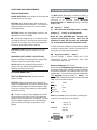
OTHER OSD IMAGE ADJUSTMENTS
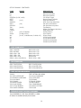
RS 232 INSTRUCTIONS
DISPLAY MENU PAGE The DVP Header, followed by a comma (no space), is
used to delimit the Header from the Command. The
following is an example, using Windows
HyperTerminal, for Power On using a standard
Modem Cable:
IMAGE POSITION: Use to adjust the horizontal and
vertical position of the image.
NOTE #1: Many digital displays will not allow any
image adjustments when using DVI. Check with the
display manual to see if there is a service mode to
allow adjustments.
dvp,on[
Enter]
Enter] denotes a carriage return, or rather,
([
pressing [
Enter] on the keyboard)
NOTE #2: Always use Image Adjust controls in the
display device first, if available.
NOTE #1: The DVP1080 goes through a 10second initiallizing process when the ON
command is sent. Do not send any commands
for 10 seconds after the ON command is sent.
Shifting the image too far to the side can cause
the image to be lost or introduce moving horizontal
gray bars in the image. Use a safe area test pattern
to properly align image position and size.
You may also issue simultaneous commands by adding
a comma to delimit each Function Command prior to
issuing the Carriage Return Command.
BLANKING LEVEL: Adjusts the gray level of the
side curtains when using 4:3 sources on a 16:9
display.
dvp,on,x,a2,srn4[
Enter]
(Control Syntax = Header, Power ON, YCrCb
(Component Input), Anamorphic, Scan Rate
1280x720[carriage return])
BLANKING (LEFT, RIGHT, TOP, BOTTOM):
Adjusts the amount of blanking for the edges of the
image to assist with proper image sizing.
NOTE: #1: Be sure image size and position is
properly set first, before setting side blanking.
Blanking can be stored as Profile.
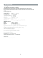
Personal Computer (PC Control)
Use the standard Windows HyperTerminal program
to control the DVP-1080. Select the options listed below
and utilize a standard 9-pin Modem Cable (not a nullmodem cable). Once connection has been established:
TYPE dvp,help and then press [
Enter]. The
OPERATION COMMANDS available will then be echoed
back to your personal computer.
PATTERNS MENU PAGE TEST PATTERNS ON/OFF: Activates the test
patterns circuit.
NOTE #1: When test patterns are activated, the
image level adjustments are fixed to reference levels
and cannot be changed. Use these patterns to align
or test your system. Many patterns are designed for
technician use only.
BPS
Data bits
Parity
Stop bits
Flow control
For best results, all image adjustments should
be done with a test DVD from the DVD player and
patterns from the satellite box, if available, This way
the final image is adjusted for the complete signal
path from source, throught the processor, to the
display.
19200
8
None
1
None
AMX and Crestron control examples; including their
respective Carriage Return commands:
AMX
“ ‘dvp,on’,13"
“ ‘dvp,off’,13"
Crestron
dvp,on\r
dvp,off\r
RS-232c Input
5
9
17
1
6
Pin 5 = Ground
Pin 3 = RX
Pin 2 = TX