1
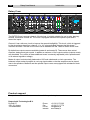
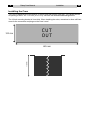
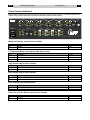
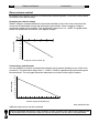
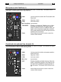
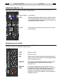
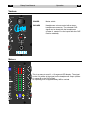
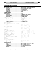
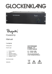
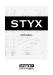
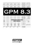
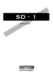
CREW
USER MANUAL
2
Dateq Crew Manual
Safety instructions
EN
Safety instructions
1
All safety instructions, warnings and operating instructions must be read first.
2
All warnings on the equipment must be heeded.
3
The operating instructions must be followed.
4
Keep the operating instructions for future reference.
5
The equipment may never be used in the immediate vicinity of water; make sure that water
and damp cannot get into the equipment.
6
The equipment may only be installed or fitted in accordance with the manufacturer's
recommendations.
7
The equipment must be installed or fitted such that good ventilation is not obstructed in any
way.
8
The equipment may never be installed in the immediate vicinity of sources of heat, such as
parts of heating units, boilers, and other equipment which generates heat (including
amplifiers).
9
Connect the equipment to a power supply of the correct voltage, using only the cables
recommended by the manufacturer, as specified in the operating instructions and/or shown
on the connection side of the equipment.
10
The equipment may only be connected to a legally approved earthed mains power supply.
11
The power cable or power cord must be positioned such that it cannot be walked on in normal
use, and objects which might damage the cable or cord cannot be placed on it or against it.
Special attention must be paid to the point at which the cable is attached to the equipment
and where the cable is connected to the power supply.
12
Ensure that foreign objects and liquids cannot get into the equipment.
13
The equipment must be cleaned using the method recommended by the manufacturer.
14
If the equipment is not being used for a prolonged period, the power cable or power cord
should be disconnected from the power supply.
15
In all cases where there is a risk, following an incident, that the equipment could be unsafe,
such as:
•
if the power cable or power cord has been damaged
•
if foreign objects or liquids (including water) have entered the equipment
•
if the equipment has suffered a fall or the casing has been damaged
•
if a change in the performance of the equipment is noticed
it must be checked by appropriately qualified technical staff.
16
The user may not carry out any work on the equipment other than that specified in the
operating instructions.
EN
Dateq Crew Manual
Introduction
3
Dateq Crew
15
20
12 9
-6 GAIN
MMi icc
0
30
15
20
3
-1
+6
0 1+
2
FFr roonnt t
RR ee aa r r
-1
5
5
-1
0 1+
2
LOW
Mic
Mic
Front
Front
HIGH
CCUUEE
I INNPPUUTT
LLi innee11
LLi innee22
3
CCUUEE
I INNPPUUTT
LLi innee11
LLi innee22
+6
4
-1
5
0
1+
2
LOW
2
3
3
4
5
I INNPPUUTT
CCUUEE
I INNPPUUTT
CCUUEE
I INNPPUUTT
LLi innee11
LLi innee22
LLi innee11
LLi innee22
4
5
5
1
2
+6
+6
R
6
LLi innee11
LLi innee22
+6
dB
L
CCUUEE
2
5
4
5
MMi icc
LLi innee
1+
4
3
4
+6
3
2
3
0
2
4
CCUUEE
3
TTaal lkkoovveer r
HIGH
3
4
-6 GAIN
I INNPPUUTT
0
30
2
3
12 9
+6
6
2
2
+1
+1
0
0
-1
-1
2
2
3
3
5
5
+3
0
-3
+3
0
-3
+3
0
-3
+3
0
-3
+3
0
-3
-6
-6
-6
-6
-6
8
8
-9
-12
-9
-12
-9
-12
-9
-12
-9
-12
12
12
20
20
-20
-20
-20
-20
-20
30
30
-30
-40
-30
-40
-30
-40
-30
-40
-30
-40
3
4
5
6
-1
0
1+
2
3
4
4
5
-1
5
1+
0
2
3
3
4
4
5
L1 0 1R
2
3
4
4
5
5
MASTER
MASTER
12 9
MM AA SS TT EE RR
CC UU EE
4
5
-1
0
3
5
0 1+
2
LOW
2
3
3
4
4
5
5
L1
0 1R
2
BAL
2
3
POWER
4
5
5
MASTER
MASTER
15
20
12 9
C
4
MMuul lt ti i- -zzoonnee
sst teer reeoommi ixxeer r
5
6
3
3
4
A
-6
HIGH
3
4
BAL
2
3
0 1+
2
5
30
AA
-1
2
3
LOW
2
15
20
7
HIGH
2
3
7
2
8
1
B
9
0
10
PHONES
-6
0
30
3
BB
+6
+6
The DATEQ Crew is a seven channel 19-inch mixer. It is highly suitable for use in pubs, dancingschools, conference centres etc. The Crew is equipped with three microphone inputs and 11
stereo-line inputs.
Channel 1 has a talk-over circuit to improve the speech intelligibility. This circuit, which is triggered
by the microphone signal from channel 1 (i.e. it is voice-activated), ensures that this signal
overrides all others. The talk-over function can be disabled with the TalkOver switch on the front.
By default two output zones are available (master A and master B). These zones have a dual
equaliser, balance and gain-control. In addition a maximum of four output modules (outputs zones)
may be added. The volume of these additional zones is externally adjustable (with a potentiometer
or an external regulation voltage).
Master A output is electronically balanced on XLR and unbalanced on cinch connectors. The
balanced output makes it possible to use long signal-cables so that the amplifiers can be placed
near to the speakers. Master B and the optional output zones are equipped with unbalanced cinch
connectors.
Product support
For questions about the Crew, accessories and other products, please contact:
Dateq Audio Technologies B.V.
De Paal 37
1351 JG Almere
The Netherlands
Phone:
Fax:
E-mail:
Internet:
+31 36 54 72 222
+31 36 53 17 776
[email protected]
www.dateq.nl
4
Dateq Crew Manual
Installation
EN
Installing the Crew
The Crew is designed to be mounted in a 19-inch rack and is three units high. The cabinet fits into
an opening of 445 x 132 x 110 mm (W x H x D). See also the dimensioned drawings below.
The 19-inch mounting bracket is 2mm thick. When installing the mixer, remember to allow sufficient
room for the connectors and plugs on the Crew’s rear!
CUT
OUT
132 mm
110 mm
445 mm
EN
Dateq Crew Manual
Connections
5
Crew Connectorboard
At the rear all the audio in and outputs can be found, just as the euro-mains connector (with built in
mains-fuse) and the optional zone outputs with the volume control inputs.
Made by
Input 7
Line 2
Almere; The Netherlands
R
Input 6
Line 1
Line 2
R
-14dB..+6dB
L
Gain
MAINS
230V/ 20VA
Gain
R
ZONE 1
ZONE 2
ZONE 3
ZONE 4
Volume Audio
Control Output
Volume Audio
Control Output
Volume Audio
Control Output
R
L
0dB
Gain
Gain
R
L
0dB
Gain
2000
Gain
R
L
0dB
Fuse: 315mA/ slow
L
-14dB..+6dB
Volume Audio
Control Output
Gain
Gain
R
L
0dB
Input 2
Line 1
R
-14dB..+6dB
L
Line 2
A
L
+6dB
Input 3
Line 1
L
L
+6dB
Line 2
R
-14dB..+6dB
R
0dB
Input 4
Line 1
Gain
R
0dB
Line 2
R
-14dB..+6dB
MASTER
A
B
TAPE
L
Gain
Input 5
Line 1
L
0dB
Line
Input 1
Mic
0dB
-50dB
L
C
Multi-zone stereo mixer
WARNING: Dangerous voltages inside. To be opened only by authorised people
Master A/ B stereo outputs (Cinch female)
Pin
Tip
Shield
Function
Audio +
Ground
Type
Out
A-GND
L/ R balanced Master (A) Outputs (XLR 3-pins male)
Pin
1
2
3
Function
Ground
Audio +
Audio -
Type
A-GND
Out
Out
Tape stereo output (Cinch female)
Pin
Tip
Shield
Function
Audio +
Ground
Type
Out
A-GND
Zone stereo output (Cinch female)
Pin
Tip
Shield
Function
Audio +
Ground
Type
Out
A-GND
Zone volume input (Cinch female)
Pin
Tip
Shield
Function
Volume control (See page 7)
Ground
Type
In
A-GND
Line/ Line 1/ Line 2 Stereo inputs (Cinch female)
Pin
Tip
Shield
Mic
-50dB
R
Function
Audio +
Ground
Type
In
A-GND
6
Dateq Crew Manual
Connections
En
Mic/ Mic Front/ Mic Rear balanced inputs (XLR 3-pins female)
Pin
1
2
3
Function
Ground
Audio +
Audio -
Type
A-GND
In
In
Phones output (TRS Jack 3p, front)
Pin
Tip
Ring
Sleeve
Function
Left
Right
Ground
Type
Out
Out
A-GND
Connections
BALANCED
MASTER L/ R (A)
Electronically balanced master outputs on XLR connectors for the left and
right channels of master A. This type of output guarantees perfect signal
transmission even if long audio cables are being used. These outputs are
equipped with relays to prevent connected equipment from ‘plopping’ when
the unit is being switched on and off.
MASTER A/ B
Unbalanced outputs on cinch connectors. These can be used to connect
the Crew to an amplifier or recorder. These outputs are equipped with relays
to prevent connected equipment from ‘plopping’ when the unit is being
switched on and off.
ZONE 1...4 Audio out With these outputs additional zones with separate external volume control
can be created. These outputs can be used to connect external amplifiers.
ZONE 1...4 Volume
This input controls the volume of the additional zone. Between the tip and
the shield a potentiometer or an external control voltage can be supplied.
See page 7 for a more detailed explanation.
CHANNEL 7...3
Cinch connectors for the stereo line inputs. Each channel has two identical
inputs (line 1 and line 2) for CD-players, keyboards, MD-players etc. With
the input-selector on the front on of the two inputs can be activated. Each
input has it’s own gain-trimmer at the rear.
CHANNEL 2
Combined mono mic/ stereo line channel with an electronically balanced
microphone input on a XLR-connector and a stereo line input on a cinch
connector. When using an unbalanced microphone pin 1 and pin 3 must be
connected to the shielding of the cable.
CHANNEL 1
This channel has two electronically balanced microphone inputs on XLRconnectors (Mic Front and Mic Rear). When using an unbalanced
microphone pin 1 and pin 3 must be connected to the shielding of the cable.
MAINS/ FUSE
Euro mains-input. The Crew operates at 230V/ 50Hz. Fuse: 5x20mm
(small), 315mA slow.
For all audio cinch connectors:
White = Left, Red = Right
EN
Dateq Crew Manual
Connections
7
Zone volume control
By means of this input the volume of an external zone can be adjusted. The volume control can be
connected in two different ways:
Supplying an external voltage
When a voltage is supplied between the tip and the shielding of one of the cinch-connectors the
volume will be attenuated (for both the left and the right channel). When a negative voltage is
supplied the signal will be amplified. The amplification ranges from +14...-80dB. The graph below
shows the amplification as function of the applied voltage:
20
10
Attenuation (dB)
0
-2
-10 0
2
4
6
8
10
-20
-30
-40
-50
-60
-70
-80
Voltage at 'volume control' (V)
Connecting a potentiometer
It is also possible to connect a potentiometer between the tip and the shielding to one of the cinch
connectors. The attenuation ranges from 0...-80dB. A 10kOhm logarithmically potentiometer gives
the best results. The next graph shows the attenuation as function of the angle of rotation:
90
80
Attenuation (dB)
70
60
50
40
30
20
10
0
0
10
20
30
40
50
60
70
80
90
100
Rotation angle potentiometer (%)
As a maximum four
additional output zones can be connected.
When an adjustable attenuation is not necessary a cinch connector with a short-circuit between the
tip and shield must be connected. When the input is left open the volume will be fully attenuated.
8
Dateq Crew Manual
Operation
EN
Microphone with TalkOver (1)
A microphone can be connected to this channel (at the front, or at the rear). The channel has a
gaincontrol, a dual equaliser and an input-selector.
12
15
9
-6
GAIN
15
MM ii cc
20
0
30
3
30
FF rr oo nn tt
RR ee aa rr
+6
0
-1
-1
2
3
2
3
4
3
4
5
0
-1
5
LOW
1+
-1
2
3
High tone control.
LOW
Low tone control.
TALKOVER
Enables or disables the TalkOver circuit. When
the button is pressed the LED lights up green
and the TalkOver function is enabled. When you
speak in the microphone all the other channels
will be attenuated and the LED will light up red to
indicate voice-over activity.
Fader
60mm fader which can be used to control the
volume of this channel.
3
4
5
HIGH
2
3
4
Volume preset for both the Mic Front and the Mic
Rear input.
Mic Front/Rear Input selector.
4
5
2
GAIN
TTaallkkoovveerr
HIGH
1+
2
12
20
4
5
5
1
M
Miicc
FFrroonntt
Combined microphone/ line channel (2)
This channel can be used to connect a microphone or a stereo line-signal. The channel has a gaincontrol, inputselector and pre-fader listening (CUE).
12
15
9
-6
20
GAIN
INPUT
CUE
0
30
GAIN
3
-1
0
+6
Mic
Line
1+
HIGH
2
Line 1
Line 2
2
3
3
4
+6
4
5
-1
+3
0
-3
5
0
1+
2
LOW
2
3
4
High tone control.
LOW
Low tone control.
Mic/ Line
Input selector.
CUE
Enables/ disabled pre-fader listening. When the
button is pressed the signal on this channel can
be heard on the headphones and is showed on
the VU-meters. The master CUE LEDs will turn
off.
Fader
60mm fader which can be used to control the
volume of this channel.
-9
-12
4
5
HIGH
-6
3
5
-20
-30
-40
1
2
Volume preset for both the microphone and the
stereo-line input.
EN
Dateq Crew Manual
Operation
9
Stereo line input (3 ... 7)
Two stereo line inputs can be connected to this channel. Each channel has an input-selector, prefader listening and a gain-trimmer on the connectorboard.
II NN PP UU TT
CC UU EE
II NN PP UU TT
LLiinnee 11
LLiinnee 22
LLiinnee 11
LLiinnee 22
+6
+6
+3
0
-3
+3
0
-3
-6
-6
-9
-12
-9
-12
-20
-20
-30
-40
-30
-40
4
Line 1/ Line 2
Input selector.
CUE
Enables/ disabled pre-fader listening. When the button
is pressed the signal on this channel can be heard on
the headphones and is showed on the VU-meters. The
master CUE LEDs will turn off.
Fader
60mm fader which can be used to control the volume
of this channel.
5
Mastersectie (A and B)
The Crew has two identical mastersections (A and B). Each section has a dual equaliser, balance
and gain control and an after-fader-listen function.
R
dB
6
-1
8
4
5
-1
5
0
1+
2
High tone control.
LOW
Low tone control.
2
BAL
Determines the balance between the left and the right
channel. When in mid-position, the left and right channel
can be heard evenly loud.
MASTER
Gaincontrol for the unbalanced stereo outputs (master
A and Master B) and the balanced stereo output
(master A only)
MASTER
CUE
Switches the headphone source between master A
and master B. The LED indicates the source (master A
or master B). When the CUE function of an inputchannel is activated both master-CUE LEDs will be
switched off, and the input-channel will be selected as
headphone source.
3
4
4
5
5
L1
0 1R
2
BAL
2
3
3
4
4
5
20
5
MASTER
30
15
20
12
9
A
-6
0
30
MM AA SS TT EE RR
CC UU EE
HIGH
LOW
3
3
12
2
4
2
5
HIGH
3
+1
0
1+
3
2
-1
0
2
3
BB
+6
10
Dateq Crew Manual
Operation
EN
Various
-1
0
HIGH
1+
POWER
2
3
4
-1
5
0
LOW
1+
2
3
4
5
L1
0 1R
BAL
2
C
4
3
5
MASTER
15
20
12
9
5
PHONES
Headphones volume control with a stereo
headphones connector. The selected CUEsignal can be heard with the headphones
(master A, master B or the inputs with the CUE
function enabled).
6
7
2
8
1
9
0
B
Mains switch.
MMuullttii--zzoonnee
sstteerreeoo mmiixxeerr
3
4
POWER
10
PHONES
-6
0
30
3
+6
Meters
CUE
L
R
dB
6
6
-1
0
2
3
2
2
+1
+1
0
0
-1
-1
2
2
3
3
4
5
-1
2
3
4
5
L1
0
This is an easy-to-read 2- x 12-segment LED display. The signal
on the VU-meters is the signal on the headphones output (master
A, master B or the CUE signal).
An operating level of approximately 0dB is nominal.
5
5
8
8
12
12
20
20
5
30
MASTER
30
2
3
4
15
20
30
A
7
0
MASTER
CUE
B
12
EN
Dateq Crew Manual
Technical Specifications
Technical Specifications
MONO INPUT
MIC (channel 1 and 2) ....................................... XLR-3 female, electronically balanced
Signal level............................................... -50 dB @ 600 Ohm variable
Impedance ............................................... 3 kOhm nominal
Input noise................................................ < -100 dB (IHF-A)
Headroom ................................................ 22 dB
STEREO INPUTS
LINE (channel 2)................................................ Cinch
Signal level............................................... 0 dB @ 600 Ohm variable
Input impedance ...................................... 12 kOhm nominal
Input noise................................................ < -70 dB (IHF-A)
Channel separation.................................. > 65 dB @ 1 kHz
LINE 1/ 2 (channel 3..7)..................................... Cinch
Signal level............................................... 0 dB @ 600 Ohm variable
Input impedance ...................................... 7 kOhm nominal
Input noise................................................ < -74 dB (IHF-A)
Channel separation.................................. > 65 dB @ 1 kHz
TONE CONTROL
EQUALISER CHANNEL 1 AND CHANNEL 2
High.......................................................... 10 kHz ±12 dB, Shelving
Low .......................................................... 30 Hz ±18 dB, Shelving
EQUALISER MASTER
High.......................................................... 12 kHz ±12 dB, Shelving
Low .......................................................... 30 Hz ±18 dB, Shelving
OUTPUTS
BALANCED MASTER (XLR)............................. +6 dB balanced/ 600 Ohm/ variable
MASTER OUT A/ B (Cinch) .............................. 0 dB unbalanced/ 600 Ohm/ variable
ZONE1...4.......................................................... 0 dB unbalanced/ 600 Ohm/ variable
PHONES (6,3 mm TRS Jack) .......................... 0,3 W @ 4 Ohm/ Impedance 4..32 Ohm
FREQUENCY RESPONSE
MIC TO MASTER .............................................. 15 Hz...25 kHz -1 dB
ALL OTHER INPUTS TO MASTER .................. 10 Hz...30 kHz -1 dB
THD + N ............................................................ 0,01 % nominal
GENERAL
BUILT-IN POWER SUPPLY
Mains voltage ........................................... 220...240 VAC / 50 Hz
Power consumption................................. 20 VA
SIZE AND WEIGHT
Front......................................................... 483 x 132 mm (W x H) = 19”, 3HE
Cutout ...................................................... 445 x 132 mm (W x H)
Cabinet depth........................................... 110 mm without connectors
Weight...................................................... 3.5 kg Net.
Dateq Audio Technologies B.V. reserves the right to amend specifications without notice
11