1
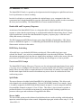
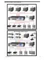
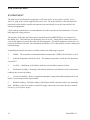
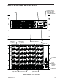
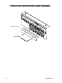
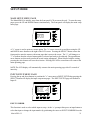
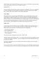
MatrixPRO- II
MATRIX SWITCHER SERIES
USER'S GUIDE
COVERS MatrixPRO-II 12X8 THROUGH 32X32 MODELS
Barco Inc. 11101-A Trade Center Drive Rancho Cordova California 95670-6119 USA 1.916.859.2500
26-0903105-00
2
MatrixPRO- II
CONTACT INFORMATION
In This Appendix
The following topics are discussed in this Appendix:
Warranty
Return Material Authorization (RMA)
Contact Information
Warranty
All video products are designed and tested to the highest quality standards and are backed by a full 3-year parts and labor warranty.
Warranties are effective upon delivery date to customer and are non-transferable. Barco warranties are only valid to the original
purchaser/owner. Warranty related repairs include parts and labor, but do not include faults resulting from user negligence, special
modifications, lightning strikes, abuse (drop/crush), and/or other unusual damages.
The customer shall pay shipping charges when unit is returned for repair. Barco will cover shipping charges for return shipments to
customers.
Return Material Authorization (RMA)
In the unlikely event that a product is required to return for repair, please call the following number and ask for a Sales Engineer to
receive a Return Merchandise Authorization number (RMA).
(888) 414-7226
RMA Conditions are listed below:
Prior to returning any item, you must receive a Return Merchandise Authorization (RMA) number.
All RMA numbers must appear on their return-shipping label.
RMA numbers are valid for ten (10) days from issue date.
All shipping and insurance charges on all RMAs must be prepaid by the customer
Contact Information
Barco, Inc.
11101 Trade Center Drive
Rancho Cordova, California 95670
USA
Phone: (916) 859-2500
Fax: (916) 859-2515
Website: www.barco.com
Sales Contact Information
Direct: (916) 859-2505
Toll Free: (888) 414-7226
E-mail: [email protected]
Barco N.V.
Noordlaan 5
8520 Kuurne
BELGIUM
Phone: +32 56.36.82.11
Fax: +32 56.35.16.51
Website: www.barco.com
Technical Support Information
Tech Line: (866) 374-7878 — 24 hours per day, 7 days per week
E-mail: [email protected]
MatrixPRO- II
3
Copyright
© Barco. February 26, 2010
All rights reserved. No part of this document may be copied, reproduced or translated. It shall not otherwise be recorded, transmitted
or stored in a retrieval system without the prior written consent of Barco.
Notice
Barco provides this manual “as is” without warranty of any kind, either expressed or implied, including but not limited to the implied
warranties or merchantability and fitness for a particular purpose. Barco may make improvements and/or changes to the product(s)
and/or the program(s) described in this publication at any time without notice.
This publication could contain technical inaccuracies or typographical errors. Changes are periodically made to the information in this
publication; these changes are incorporated in new editions of this publication.
Federal Communications Commission (FCC) Statement
This equipment has been tested and found to comply with the limits for a class A digital device, pursuant to Part 15 of the FCC
rules. These limits are designed to provide reasonable protection against harmful interference when the equipment is operated in a
commercial environment. This equipment generates, uses, and can radiate radio frequency energy and, if not installed and used in
accordance with the instruction manual, may cause harmful interference to radio communications. Operation of this equipment in a
residential area may cause harmful interference, in which case the user will be responsible for correcting any interference.
Guarantee and Compensation
Barco provides a guarantee relating to perfect manufacturing as part of the legally stipulated terms of guarantee. On receipt,
the purchaser must immediately inspect all delivered goods for damage incurred during transport, as well as for material and
manufacturing faults Barco must be informed immediately in writing of any complaints.
The period of guarantee begins on the date of transfer of risks, in the case of special systems and software on the date of
commissioning, at latest 30 days after the transfer of risks. In the event of justified notice of compliant, Barco can repair the fault or
provide a replacement at its own discretion within an appropriate period. If this measure proves to be impossible or unsuccessful, the
purchaser can demand a reduction in the purchase price or cancellation of the contract. All other claims, in particular those relating
to compensation for direct or indirect damage, and also damage attributed to the operation of software as well as to other services
provided by Barco, being a component of the system or independent service, will be deemed invalid provided the damage is not
proven to be attributed to the absence of properties guaranteed in writing or due to the intent or gross negligence or part of Barco.
If the purchaser or a third party carries out modifications or repairs on goods delivered by Barco, or if the goods are handled
incorrectly, in particular if the systems are commissioned operated incorrectly or if, after the transfer of risks, the goods are subject to
influences not
agreed upon in the contract, all guarantee claims of the purchaser will be rendered invalid. Not included in the guarantee coverage are
system failures which are attributed to programs or special electronic circuitry provided by the purchaser, e.g. interfaces. Normal wear
as well as normal maintenance are not subject to the guarantee provided by Barco either.
The environmental conditions as well as the servicing and maintenance regulations specified in this manual must be complied with by
the customer.
Trademarks
Brand and product names mentioned in this manual may be trademarks, registered trademarks or copyrights of their respective
holders. All brand and product names mentioned in this manual serve as comments or examples and are not to be understood as
advertising for the products or their manufactures.
4
MatrixPRO- II
Company Address
Barco Inc.
11101 Trade Center Drive
Rancho Cordova, California 95670
USA
Phone: (916) 859-2500
Fax: (916) 859-2515
Website:
www.barco.com
Barco N.V.
Noordlaan 5
8520 Kuurne
BELGIUM
Phone: +32 56.36.82.11
Fax: +32 56.35.16.51
Technical Support
Customer Service Portal — www.barco.com/esupport
(866) 374-7878 — Events (24/7)
(866) 469-8036 — Digital Cinema (24/7)
MatrixPRO- II
5
Operators Safety Summary
The general safety information in this summary is for operating personnel.
Do Not Remove Covers or Panels
There are no user-serviceable parts within the unit. Removal of the top cover will expose dangerous voltages. To avoid personal
injury, do not remove the top cover. Do not operate the unit without the cover installed.
Power Source
This product is intended to operate from a power source that will not apply more than 230 volts rms between the supply conductors
or between both supply conductor and ground. A protective ground connection by way of grounding conductor in the power cord is
essential for safe operation.
Grounding the Product
This product is grounded through the grounding conductor of the power cord. To avoid electrical shock, plug the power cord into a
properly wired receptacle before connecting to the product input or output terminals.
A protective-ground connection by way of
the grounding conductor in the power cord is essential for safe operation.
Use the Proper Power Cord
Use only the power cord and connector specified for your product. Use only a power cord that is in good condition. Refer cord and
connector changes to qualified service personnel.
Use the Proper Fuse
To avoid fire hazard, use only the fuse having identical type, voltage rating, and current rating characteristics. Refer fuse replacement
to qualified service personnel.
Do Not Operate in Explosive Atmospheres
To avoid explosion, do not operate this product in an explosive atmosphere.
6
MatrixPRO- II
Terms In This Manual and Equipment Marking
WARNING
Highlights an operating procedure, practice, condition, statement, etc., which, if not strictly observed, could result in injury to or death
of personnel.
Note
Highlights an essential operating procedure, condition or
statement.
CAUTION
The exclamation point within an equilateral triangle is intended to alert the user to the presence of important operating and
maintenance (servicing) instructions in the literature accompanying the appliance.
AVERTISSEMENT!
Le point d´exclamation dans un triangle equilatŽral signale à alerter l´utilisateur qu´il y a des instructions d´operation et d´entretien
tres importantes dans la litŽrature qui accompagne l´appareil
.
VORSICHT
Ein Ausrufungszeichen innerhalb eines gleichwinkeligen Dreiecks dient dazu, den Benutzer auf wichtige Bedienungs-und
Wartungsanweisungen in der Dem
Great beiliegenden Literatur aufmerksam zu machen.
MatrixPRO- II
7
Change History
Rev
8
Date
ECP #
Description
Approved By
00.00
4/1/10
577375
Initial Release
R. Pellicano
01.00
4/22/10
577971
Updated feature descriptions and menus
R. Pellicano
MatrixPRO- II
TABLE OF CONTENTS
CONTACT INFORMATION .............................................................................................................3
IN THIS APPENDIX...............................................................................................................................................3
WARRANTY...........................................................................................................................................................3
RETURN MATERIAL AUTHORIZATION (RMA) ..............................................................................................3
CONTACT INFORMATION ..................................................................................................................................3
OPERATORS SAFETY SUMMARY ................................................................................................6
TERMS IN THIS MANUAL AND EQUIPMENT MARKING .....................................................7
CHANGE HISTORY ...........................................................................................................................8
INTRODUCTION..............................................................................................................................11
BANDWIDTH AND FREQUENCY RESPONSE ............................................................................................... 11
RGB DELAY SWITCHING ................................................................................................................................. 11
PRESETS AND I/O GROUPS .............................................................................................................................. 11
SPLIT MODE ........................................................................................................................................................ 11
STEREO AUDIO .................................................................................................................................................. 11
SERIAL AND IP CONTROL................................................................................................................................12
FEATURES .......................................................................................................................................12
APPLICATIONS................................................................................................................................12
APPLICATION EXAMPLES...........................................................................................................13
NATIVE MODE APPLICATION .........................................................................................................................13
SPLIT MODE APPLICATION .............................................................................................................................13
INSTALLATION ...............................................................................................................................14
ENVIRONMENT ..................................................................................................................................................14
AUDIO INPUT WIRING ......................................................................................................................................15
AUDIO OUTPUT WIRING ..................................................................................................................................15
RJ-45 LAN INTERFACE CABLING ...................................................................................................................16
RS-232 REMOTE HOST PORT CABLING (DB9) .............................................................................................16
LCD DISPLAY MENU TREE ..........................................................................................................17
UNDERSTANDING THE LCD DISPLAY......................................................................................18
LED INDICATOR LAMP BEHAVIOR...........................................................................................18
FRONT AND REAR PANEL VIEWS..............................................................................................19
MatrixPRO- II
9
INSTALLING THE LEGEND LABEL ASSEMBLY .....................................................................20
SETUP MODE ...................................................................................................................................21
MAIN SETUP MENU PAGE................................................................................................................................21
INPUT SETUP MENU PAGE...............................................................................................................................21
OUTPUT SETUP MENU PAGE...........................................................................................................................24
SYSTEM SETUP MENU PAGE ..........................................................................................................................26
PRESET SETUP MENU PAGE ............................................................................................................................29
OPERATING MODE ........................................................................................................................32
MAIN OPERATING PAGE: ................................................................................................................................32
VOLUME HANDLING PAGE .............................................................................................................................33
EXECUTING PRESETS.......................................................................................................................................35
FACTORY RESET ................................................................................................................................................36
SCREENPRO-II/SCREENPRO-II CONTROLLER SETUP .......................................................37
CONFIGURING THE SCREENPRO-II ...............................................................................................................37
SETTING UP THE SCREENPRO-II CONTROLLER ....................................................................................... 37
SPECIFICATIONS ............................................................................................................................41
UPDATING SOFTWARE .................................................................................................................43
SOFTWARE UPDATE OVERVIEW ....................................................................................................................43
HARDWARE REQUIREMENTS.........................................................................................................................43
DOWNLOADING SOFTWARE ..........................................................................................................................43
UPDATING MATRIXPRO-II SOFTWARE .........................................................................................................45
10
MatrixPRO- II
INTRODUCTION
The MatrixPRO-II family is a ground-up development aimed at bringing new capabilities and a new
level of performance to matrix switching.
In order for a display to accurately reproduce the original image, every component in the video
system must have enough bandwidth to carry the signal and be as flat as possible in order to maintain
the clarity and color fidelity. The MatrixPRO-IIs set a new standard in both areas.
Bandwidth and Frequency Response
At the heart of the MatrixPRO-II Series is a design that delivers high bandwidth and flat frequency
response to insure that the original image is switched and distributed without being altered. Proper
signal reproduction is much more than bandwidth. Frequency response plays a vital role in the
clarity and accuracy of an image.
The HD Component and RGB units feature greater than 600 MHz of bandwidth to -3dB. Better,
from 0 to 300MHz the signal is +/-1.0 dB making the MatrixPRO-IIs the highest bandwidth and
flattest matrix switchers on the market.
RGB Delay Switching
All models have a user definable RGB delay switch mode. When enabled and a new route
selected, the H and V sync switch on command and black is sent down the RGB lines. This allows
downstream equipment to lock into the new signal before anything is visible on the screen. After the
preset interval, the RGB signal is then restored making the switch appear as clean as possible.
Presets and I/O Groups
The MatrixPRO-II' family offers up to 32 presets, one for each input and output button. Presets make
a very easy way to reconfigure all of the routes in a system with the touch of a button. I/O groups are
handy if there are some inputs or outputs that must be isolated from one another. An example would
be that certain inputs from the executive boardroom may never wish to be switched to the video
conferencing system.
Split Mode
The newest feature to be added to the MatrixPRO-II is Split Mode Switching. This allows each
color channel to be switched independently. Take an 12x8 RGBHV matrix as an example. Inputs
1-4 could be assigned to be RGB while the Red channel on inputs 5-8 can be composite while the
Green and Blue channels on inputs 9-12 are S-Video. This allows 1 physical matrix switcher to
perform the duties of several units saving money by ensuring that the switching capabilities are
present as video types and resolutions are upgraded in the future.
Stereo Audio
The stereo audio option provides balanced and unbalanced stereo audio switching with independent
input trim control and output volume control. Independent input gain switches allow unity or +14 dB
MatrixPRO- II
11
gain settings for each input to maintain optimal S/N ratio.
Serial and IP Control
The MatrixPRO-II command set is an easy to follow easy to implement ASCII command set that
gives control systems complete access to all functions. Each unit is equipped with an RS-232 serial
port along with an IP port for today’s remote communications systems.
NOTE: The default IP Address is: 192.168.0.244
FEATURES
Very High and Very Flat Bandwidth
600MHz of Bandwidth to -3dB
+/-1.0 dB to 300MHz
Sizes to Fit the Install
12x8, 16x16 and 32x32 sizes available
Composite, S-Video, Component and RGBHV configurable
HD Compatible
720p, 1080i, 1080p and 2k by 1k Digital Cinema
Split Mode Switching
Optional Balanced Stereo Audio (Audio models only)
+/-10 dB Input Trim
Pro / Consumer Pad
-45 to +5 Output Volume Control
32 Presets
RS-232 and IP Remote Control
APPLICATIONS
♦
♦
♦
♦
♦
♦
♦
♦
♦
12
Boardrooms
Schools
House of Worship
Rental and Staging
Convention Centers
Divisible Ballrooms
Security and Surveillance System Integration
Μοnitoring Centers
Courtrooms
MatrixPRO- II
APPLICATION EXAMPLES
NATIVE MODE APPLICATION
SPLIT MODE APPLICATION
MatrixPROi
II
13
INSTALLATION
ENVIRONMENT
The Matrix rack unit should be mounted in a rack where an AC power outlet is nearby. It is a
direct AC plug in unit via the supplied EIA power cord. The front and back of the unit should be
positioned so that both the installer and operator can conveniently access the front and back for
wiring and adjustments.
Check each the manufacturer's recommendations on cable requirements and termination. Use standard approved wiring practices.
The integrity of all audio and video sources should be pretested BEFORE they are connected to
the Matrix rack. This holds true for the display devices as well. Simply direct connect the various
sources and displays to pretest the cable runs and equipment. The tested equipment can then be connected to the Matrix rack unit. All terminations should have "ID" cable markers to aid in cabling and
troubleshooting.
In installing the Matrix rack unit in a suitable manner, the following is required:
1.
TMRA – The maximum recommended ambient temperature (TMRA) for the Matrix is 40°C.
2.
Ambient Temperature Inside the Rack – The ambient temperature inside the rack should not
exceed 40°C.
3.
Air Flow – Installation of the Matrix inside the rack should not impede air flow.
4.
Mechanical Loading – Mounting of the Matrix inside the rack shall not result in a hazardous
condition due to uneven loading.
5.
Circuit Overloading – Refer to equipment nameplate ratings when addressing branch circuit
and/or overcurrent protection requirements.
6.
Reliable Earthing – Reliable earthing of the Matrix shall be maintained after rack mounting.
Note – Earthing via the rack could be required if supply connection is not made directly to branch
circuit (e.g. use of power strips).
14
MatrixPRO- II
WIRING DETAIL FOR MatrixPRO-II MODELS WITH AUDIO OPTION
MatrixPRO-II AUDIO INPUT CONNECTOR WIRING
FROM A STEREO
UNBALANCED SOURCE
FROM A MONO
UNBALANCED SOURCE
AUDIO INPUT WIRING
I
N
P
U
T
SHIELD
SHIELD
L+
L-
SH
I
N
P
U
T
SIGNAL
FLOW
R+
INSTALL JUMPER
R-
L+
OPTIONAL JUMPER
L-
SH
SIGNAL
FLOW
R+
R-
INSTALL JUMPERS
OPTIONAL JUMPER
FROM A STEREO BALANCED
SOURCE
FROM A MONO BALANCED
SOURCE
I
N
P
U
T
I
N
P
U
T
SIGNAL
FLOW
SIGNAL
FLOW
SHIELD
(2) SHIELD
L+
L-
SH
R+
R-
L+
L-
SH
R+
R-
INSTALL JUMPERS
MatrixPRO-II AUDIO OUTPUT CONNECTOR WIRING
TO A STEREO UNBALANCED
PREAMP INPUT
TO A MONO UNBALANCED
PREAMP INPUT
O
U
T
P
U
T
O
U
T
P
U
T
SIGNAL
FLOW
SIGNAL
FLOW
AUDIO OUTPUT WIRING
COMMON
COMMON
L+
L-
SH
R+
R-
INSTALL JUMPER
L+
OPTIONAL JUMPER
L-
SH
R+
R-
OPTIONAL JUMPER
INSTALL JUMPER
TO A STEREO BALANCED
PREAMP INPUT
TO A MONO BALANCED
PREAMP INPUT
O
U
T
P
U
T
O
U
T
P
U
T
SIGNAL
FLOW
SIGNAL
FLOW
SHIELD
(2) SHIELD
L+
L-
SH
R+
R-
L+
L-
SH
R+
R-
INSTALL JUMPER
MatrixPRO- II
15
RJ-45 LAN Interface Cabling
This port is used to access the MatrixPRO-II via TCP-IP from
a host computer or network.
Cable type:
RJ-45 Crossover for direct computer to MatrixPRO-II control
RJ-45 Straight through for Network to MatrixPRO-II control
Recommended Maximum Length: 329 feet
Crossover Cable
Standard Patch Cable
NOTE: The default IP Address is: 192.168.0.244
RS-232 Remote Host Port Cabling (DB9)
CABLE
PC
(typical)
The MatrixPRO-II has a standard RS-232
(DB9F) communication port that connects the
host PC to the Rack Unit allowing control and
configuration.
Cable Type: Straight through DB-9 Male (To
mate with Female on Rack Unit) to DB-9
Male (to mate with DB-9 Male on typical PC
COMM port).
Recommended Maximum Length: 50 ft
16
DB9M
(DTE)
DB9F
DB9M
RN Remote
RS-232
Host Port
RX
2
2
2
2
TX
TX
GND
3
5
3
5
3
5
3
5
RX
GND
CTS
RTS
8
7
8
7
DSR
CD
DTR
6
2
4
6
2
4
Optional Flow Control Connections
8
7
8 RTS
7 CTS
If the device requires DSR, CD, or DTR,
implement loop -back handshake at the
device end of the cable as shown .
MatrixPRO- II
EXECUTE
PRESET
PRESET
OUTPUT
AUDIO
VOLUME
VOL
MAIN PAGE
MatrixPRO- II
AUDIO
TYPE
INPUT
TRIM
OUTPUT
LEVEL
OUTPUT
MUTE
OUTPUT
SETUP
INDICATES SCREEN IS VISIBLE ON CERTAIN MODELS
OR OPERATING CONDITIONS ONLY
CABLE
LENGTH
VIDEO
TYPE
INPUT
NUMBER
OUTPUT
NUMBER
INPUT
SETUP
CABLE
LENGTH
0' - 150'
ON/OFF/AUTO
SYNC EQ
RGB
DELAY
VIDEO
TYPE
OUTPUT
NUMBER
LCD
SETUP
REMOTE
PANELS
DUET TCP/
IP SETUP
SET TIME/
DATE
SET TIME/
DATE
866#
VERSION
INFO
TECH
SUPPORT
TO ENTER)
DELAY
TIME
SET
CONTRAST/
BRIGHTNESS
AND
SYSTEM
SETUP
MAIN SETUPS (PRESS
PRESET
SETUP
SAVE
SELECTED
SAVE ALL
OUTPUTS?
PRESET
NUMBER
RESET
MATRIX
ARE YOU
SURE?
RETURN TO
SETUPS
RETURN TO
FACTORY
SETTINGS
LCD DISPLAY MENU TREE
17
UNDERSTANDING THE LCD DISPLAY
SELECT
BARCO
MATRIXPRO-II
PRESET VOL
ESCAPE
LCD SCREEN: The visual interface for the MatrixPRO-II rack
SELECT PUSH BUTTON: used to select a menu item or an AV route
UP AND DOWN ARROW PUSH BUTTONS: increases or decreases a menu value such as volume
level or a numeric value. Also used to scroll through menu items.
ESCAPE PUSH BUTTON: allows the user to cancel a command and back out to the previous menu
page
ON SCREEN MENU ITEM SELECT PUSHBUTTONS(4): used to select page menu items that are
located above the individual push buttons on the LCD screen. Functions will vary and are dependant
on page status In the example below, the two left push buttons are for preset and volume settings
respectively
ON LCD SCREEN CURSORS:
• A ">" is used to point to a menu item.
• A "*" indicates that the menu item has been selected.
LED INDICATOR LAMP BEHAVIOR
The color and state of the indicator LED's provide the following status information. This holds true
for ALL LED's on the rack:
• RED LED: indicates Video
z GREEN LED: indicates Audio
z STEADY LED: a routed input or output
z FLASHING LED: indicates an available input or output
18
MatrixPRO- II
FRONT AND REAR PANEL VIEWS
INPUT SELECT
LCD DISPLAY
SOURCE SELECT
BUTTONS - PUSH
SIMULTANEOUSLY
TO ENTER PROGRAM
MODE
LCD FUNCTION BUTTONS
VIDEO INPUT
(1 THRU 8)
VIDEO OUTPUT
(1 THRU 16)
OUTPUT SELECT
VIDEO INPUT
(9 THRU 16)
AC POWER
INPUT
RS-232
REMOTE
OR SERIAL
CONTROL
PORT 0
RJ45 LAN
INTERFACE
AUDIO INPUT
(1 THRU 8)
AUDIO OUTPUT
(1 THRU 16)
AUDIO INPUT
(9 THRU 16)
BARCO MSRF-1616 SHOWN
MatrixPRO- II
19
INSTALLING THE LEGEND LABEL ASSEMBLY
PRINT LABEL STRIP FROM CD-ROM,
FILE NAME : MATRIX LABEL.DOT
20
MatrixPRO- II
SETUP MODE
MAIN SETUP MENU PAGE
The MatrixPRO-II is initially setup from the front panel LCD screen on the rack. To enter the setup
pages, press the UP and DOWN buttons simultaneously. The front panel will display the main setup
menu page:
SELECT
MAIN SETUPS
>INPUT SETUP
OUTPUT SETUP
SYSTEM SETUP
PRESET SETUP
RESET MATRIX
ESCAPE
A ">" cursor is used to point to a menu option. The ">" cursor is moved up and down using the UP
and DOWN arrow buttons to the right of the LCD screen. Pressing the SELECT button causes the
front panel to enter the menu or sub-menu page that is next to the cursor. The ">" will change to a
"*" to indicate that the selected menu option is selected and ready to be adjusted. The up and down
arrow buttons are then used to make the actual setting adjustment. When satisfied with the setting,
pressing the select button will save the selection. Pressing ESCAPE a second time will return to the
main operating page.
NOTE: The LCD display will automatically return to the main operating page after 45 seconds of
inactivity.
INPUT SETUP MENU PAGE
Pressing the up and down buttons to position the ">" cursor next to INPUT SETUP then pressing the
SELECT button will display the input setup menu pages. The INPUT SETUP page will default to
Input 01.
SELECT
INPUT SETUP
01
>INPUT NUMBER
CON
AUDIO TYPE
-5 dB
INPUT TRIM
NATIVE
VIDEO TYPE
0
CABLE LENGTH
SAVE
ESCAPE
INPUT NUMBER
This function is used to select which input to setup. At the “>“ prompt either press an input button to
select that input or change the input number by positioning the cursor to INPUT NUMBER Press the
MatrixPRO- II
21
SELECT button. The UP and DOWN buttons can then be used to scroll through the input adjustment
options and press select to choose one of the following options.
AUDIO TYPE
The user can, after selecting an input, adjust the parameters for that input. The user may scroll down
to AUDIO TYPE and select between PRO for profession, and CON for consumer types of audio
input. AUDIO TYPE is only available on units with the audio option.INPUT TRIM
The user may choose to adjust the audio INPUT TRIM. It may be desirable that the input’s audio
be connected to an output audio, so the user can hear the adjustment. The range of the input trim
will be –10dB to +10dB in one dB increments. The user scrolls down to INPUT TRIM and presses
SELECT. The user uses the UP and DOWN buttons to change the input’s trim value. The front panel
will send an Input Trim value message to the rack each time the value is changed so the user can
hear the difference. INPUT TRIM is only available on units with the audio option.
VIDEO TYPE
A unique feature of the MatrixPRO-II series is the ability to configure inputs (and outputs) for not
only the default source type, but also be able to split the port in order to input other source types.
When an input is set to split mode, an RGB matrix port can be configured as:
•
•
•
•
One RGB port, (Default)
One Component video
One S-Video and one composite
Three Composites.
The ports will default to RGB.and NATIVE for the VIDEO TYPE.
If the user wishes to split an input in order to use another video type(s), the user positions the cursor
to VIDEO TYPE and presses SELECT. The user can toggle between NATIVE and SPLIT by using
the up and down buttons.
If the input is split and the user selects NATIVE, the front panel will simply return to the default
video setting of RGB.
If the user chooses SPLIT , and presses the SELECT button, the screen will change to allow the user
to scroll through and select one of five pre-defined split configurations. The screen will look like this:
22
MatrixPRO- II
SELECT
SPLIT SETUP
>A RGB
B RGB
C RGB
SAVE
ESCAPE
The "A-B-C" (labeled R-G-B on the unit) designations refer to the physical location of the video
cards from top to bottom in the MatrixPRO-II chassis Pressing the UP and DOWN buttons will
scroll through the five available configurations. In this example the input is set to one S-video and
one Composite video
SELECT
SPLIT SETUP
*A SVIDEO
B SVIDEO
C COMPOSITE
SAVE
ESCAPE
Pressing SAVE will store the selected configuration for that input. The user can then select another
input to set up, or press the ESCAPE button to return to the INPUT SETUP menu.
CABLE LENGTH (Input)
CABLE LENGTH gives the user the ability compensate for the length of cable from the source to
the MatrixPRO-II. The user will scroll down to CABLE LENGTH press SELECT. The user will
then use the UP and DOWN buttons to adjust the cable length from 00’to 150’ in 10 foot lengths.
When finished the user will press SELECT to save the setting.
NOTE: A final phase adjustment of the display should be performed after cable EQ
adjustments are completed to optimize the image quality
MatrixPRO- II
23
OUTPUT SETUP MENU PAGE
There are three differences between the input and output setup screens. One is that on the input
screen the user will be able to adjust the audio input trim. The second difference between an RGB
input and RGB output is the ability to enable or disable the RGB delay on the RGB output. The
third difference is the ability to enable and set sync equalization. Below is a screen for output 1.
The method of setting the output type works exactly the same as the input type setup except that the
message changes from input to output. The user can either choose an output directly using one of the
output buttons or use the UP, DOWN, and SELECT buttons to choose the output.
SELECT
OUTPUT SETUP
01
>OUTPUT NUMBER
NATIVE
VIDEO TYPE
OFF
RGB DELAY
OFF
SYNC EQU
0
CABLE LENGTH
SAVE
ESCAPE
RGB DELAY
RGB DELAY is used so that the display can sync up to the new sources' sync signals before
switching in the new source video. RGB DELAY is only for the RGB matrix and can be set as ON or
OFF (will not appear on the display when in split mode or on non-RGB models).
SYNC EQU
SYNC EQU is a feature designed to restore sync rise and fall time to compensate for losses in sync
levels over long cable runs. There are three settings: OFF, ON, or AUTO. When set to AUTO, sync
equalization will automatically turn on when CABLE LENGTH setting is set to 50' or more (will not
appear on the display when in split mode or on non-RGB models)
CABLE LENGTH (Output)
CABLE LENGTH gives the user the ability to compensate for the length of cable from the
MatrixPRO-II to the display. The settings are from 0 to 150 feet in increments of 10 feet. Zero feet
is off. The user presses the up and down buttons to select the length and presses the SELECT button.
NOTE: A final phase adjustment of the display should be performed after cable EQ
adjustments are completed to optimize the image quality
24
MatrixPRO- II
VIDEO TYPE
A unique feature of the MatrixPRO-II series is the ability to configure outputs (and inputs) for not
only the default video type, but also be able to split the port in order to output video types. When an
output is set to split mode, an RGB matrix port can be configured as:
•
•
•
•
One RGB port, (Default)
One Component video
One S-Video and one composite
Three Composites.
The ports will default to RGB.and NATIVE for the VIDEO TYPE.
If the user wishes to split an output in order to use another video type(s), the user positions the
cursor to VIDEO TYPE and presses SELECT. The user can toggle between NATIVE and SPLIT by
using the up and down buttons.
If the output is split and the user selects NATIVE, the front panel will simply return to the default
video setting of RGB.
If the user chooses SPLIT , and presses the SELECT button, the screen will change to allow the user
to scroll through and select one of five pre-defined split configurations. The screen will look like this:
SELECT
SPLIT SETUP
>A RGB
B RGB
C RGB
SAVE
ESCAPE
The "A-B-C" (labeled R-G-B on the unit) designations refer to the physical location of the video
cards from top to bottom in the MatrixPRO-II chassis Pressing the UP and DOWN buttons will
scroll through the five available configurations. In this example the output is set to one S-video and
one Composite video
SELECT
SPLIT SETUP
*A SVIDEO
B SVIDEO
C COMPOSITE
SAVE
ESCAPE
Pressing SAVE will store the selected configuration for that output. The user can then select another
output to set up, or press the ESCAPE button to return to the OUTPUT SETUP menu.
MatrixPRO- II
25
SYSTEM SETUP MENU PAGE
SYSTEM SETUP MENU PAGE allows the user to view and set system parameters from the
front panel. The system setup main menu page looks like this:
SELECT
SYSTEM SETUP
TECH SUPPORT
SET TIME AND DATE
TCP/IP - DUET SETUP
PANELS
NO
*REMOTE
LCD SETUP
DELAY TIME 00.0 SAV
ESCAPE
TECH SUPPORT
TECH SUPPORT brings up a screen that looks like this.
SELECT
TECH SUPPORT
FP APP
X.XX
MU APP
XX.XX
FP LDR
X.XX
MU LDR
XX.XX
FOR TECH SUPPORT:
1 (866 ) 374-7878
ESCAPE
The screen reports the front panel’s application version and the matrix application version. The
FL and ML numbers are the front panel and main unit loader versions. It will have the Barco 866
number as the tech support number. Pressing the ESCAPE or BACK button will return to the system
setup menu.
SET TIME DATE
SET TIME DATE sets the real time clock to the current time and date. The time and date will be
used in the future to schedule events, such as presets that are recurring.
The user selects SET TIME AND DATE. During the setting of date and time, the SELECT button is
used to navigate through the different fields. To move to the next field the user presses the SELECT
button. To save the date and time the user will need to press SAVE; which may be pressed at any
time, after saving the new time and date the SAVE button will return to the system setup menu. The
ESCAPE button is used to return to the SYSTEM SETUP main page.
26
MatrixPRO- II
The set time and date screen looks like this:
SELECT
SET TIME/DATE
TIME
01:00 am
DATE
01/01/01
SAVE
ESCAPE
The user presses the SELECT button, the display changes to the following screen:
SELECT
SET TIME/DATE
01
TIME
01:00
am
DATE
01/01/01
SAVE
ESCAPE
This signifies that the user can now change the hour value; the user would use the UP and DOWN
buttons to change the hour setting. When the user is finished setting the hour the user will press the
SELECT button, which would change the display as follows:
SELECT
SET TIME/DATE
00 am
TIME
01:00
DATE
01/01/01
SAVE
ESCAPE
The user can set the current minutes month day and year in the same fashion as above by pressing
the SELECT button to scroll to the next desired field and select a value using the UP and DOWN
buttons. The user may press ESCAPE at any point to return to the SYSTEM SETUP menu (settings
will not be saved).
When finished setting time and date, press the SAVE button. Pressing the SAVE button will save the
new settings. A "Saving time and date " message will appear briefly on the LCD screen. The front
panel will then return to the system setup menu.
MatrixPRO- II
27
DUET TCPIP/IP SETUP
TCPIP/IP-DUET SETUP brings up a screen that looks like this.
SELECT
DUET TCP/IP SETUP
>AMX DUET
DISABLED
DHCP
DISABLED
IP
XXX.XXX.XXX.XXX
MC 00-50-C2-9F-40-A8
SAV
ESCAPE
AMX DUET
The user can cnable the use of AMX Duet by selecting AMX DUET, using the up down buttons to
scroll and selecting ENABLE. When enabled, the MatrixPRO-II will send a UDP beacon that can be
discovered by an AMX DUET system.
DHCP and IP
When DHCP is enabled, the MatrixPRO-II will request an IP address from the DHCP server on the
local network it is connect to. When DHCP is DISABLED, a static IP address can be set. Scroll to
IP and press SELECT. Use the UP and DOWN buttons to change the numeric value of the first three
digit group and press SELECT. The three indicator arrows will move to the next three digit group to
be set. Continue this procedure to set the desired static IP address.
Pressing SAV will save the settings above.
REMOTE PANELS SETUP under SYSTEM SETUP is used when a MatrixPRO-II Remote Panel
is connected to the MatrixPRO-II. Once selected, the user can choose "YES or "NO" to activate or
deactivate a MatrixPRO-II Remote Panel.
SELECT
SYSTEM SETUP
TECH SUPPORT
SET TIME AND DATE
TCP/IP - DUET SETUP
PANELS
YES
*REMOTE
LCD SETUP
DELAY TIME 00.0 SAV
ESCAPE
28
MatrixPRO- II
LCD APPEARANCE SETUP
FRONT PANEL SETUP brings up the following screen:
SELECT
FRONT PANEL SETUP
>CONTRAST
44
BACKLIGHT
100%
ESCAPE
This screen allows adjustment of the CONTRAST and BACKLIGHT on the LCD display, .
CONTRAST deals with the difference in shade between the characters and the background, the
higher the number the bigger the difference.
DELAY TIME
DELAY TIME sets the RGB time delay for all RGB outputs. This is a global setting. RGB delay is
independently enabled or disabled via the output setup for any given RGB output.
The time range is .1 to 10.0 seconds with 00.0 indicating off. Each RGB output’s setup has the
ability to turn on or off RGB delay. The user will position the cursor using UP or DOWN buttons to
DELAY TIME and presses SELECT. The user then uses the UP and DOWN buttons to set the delay
time to the correct seconds, and tenths of seconds. Pressing the SELECT button then sets and stores
the delay time setting.
PRESET SETUP MENU PAGE
All MatrixPRO-II models have 32 presets. Presets are accessed on the front panel either by pressing
an input or output select button, or using the UP and DOWN buttons and SELECT to choose a
preset not represented by an input or output button. For example if the matrix is a 12X8 matrix, only
presets 1 to 20 can be accessed using an input or output button. Presets 21 to 32 will need to be
accessed using the UP, DOWN and SELECT buttons. Preset numbers accessed by the input and
output buttons are determined by the button they are associated with. For example; on a 12 X 8
matrix output, button 3 would represent preset 15, output button 8 would be preset 20.
The user can set presets by using the SETUP PRESET function. The user can set a preset in two
ways; saving the current output matrix settings to a preset, and defining a preset based on selected
outputs.
MatrixPRO- II
29
The screen for the preset setup will look like this:
SELECT
PRESET SETUP
>PRESET NUMBER
SAVE ALL OUTPUTS
SAVE SELECTED
ESCAPE
The user can choose a preset number either by pressing an input or output button or using the UP,
DOWN and SELECT buttons. If the user wishes to save the current settings as the preset, the user
will position the cursor to SAVE ALL OUTPUTS and presses SAVE.
To only include certain outputs into the preset, the user will select SAVE SELECTED, then choose
the outputs (using the output buttons) that are to be included in the preset. If the output is not
split, the user will have the option of selecting VIDEO, AUDIO or both by pressing the VIDEO
and AUDIO buttons.. The following screen will be displayed to allow the user to confirm that the
settings are correct and to select video and/or audio.
If the settings are correct the user will press SELECT and this output will be saved locally until
the ESCAPE button is pressed. When finished selecting outputs the user will press ESCAPE and
is prompted to save the preset. If the user presses SELECT at the YES prompt, the preset will be
saved to the main unit.
SELECT
01
SELECTED PRESET
OUTPUT NUMBER
CHOOSE OUTPUT NUMBER
THEN
VID/AUD
THEN
'SELECT' SAVES
OUTPUT TO PRESET
ESCAPE
30
MatrixPRO- II
If the output selected is split the user will have to decide which of the output’s cards the user wishes
to include in the preset. The following screen will be displayed.
SELECT
SELECTED PRESET
OUTPUT NUMBER
A
02
SVD
B
02
SVD
C
NC
CVD
01
07
NC
AUD
ESCAPE
In this example output 7 is setup as a S-Video input on “A” and “B” and a Composite video on “C”.
The front panel also shows which input is currently connected to each card. The user will then select
which video cards the user wishes to include in preset 1. The user can also select output 7’s audio to
be included in the preset. Pressing the SELECT button will save the selected output 7 cards locally.
MatrixPRO- II
31
OPERATING MODE
The main purpose of the matrix is to connect inputs to outputs; the front panel is one method of
accomplishing this. The main screen is used and will look something like this:
MAIN OPERATING PAGE:
Main operating page with audio option
SELECT
BARCO
MATRIXPRO-II
PRESET VOL
ESCAPE
Pressing the VIDEO button for connecting video, the AUD button for switching audio, both VIDEO
and AUD to switch both. Pressing the VOL button allows the user to select and adjust an output
audio level. Pressing the PRESET button allows the user to select a preset to execute.
Main operating page without audio option
SELECT
BARCO
MATRIXPRO-II
PRESET
ESCAPE
The main screen is used to select the connection type, and which inputs and outputs are to be
connected. Pressing the VIDEO button sets the connection as a video connection. Pressing the
AUDIO button sets the connection as a audio connection Pressing both the VIDEO and AUDIO
buttons indicate that the connection will connect both the video and audio. The user may also press
an input or output select button at this screen that would cause the matrix to go into connection
mode. When connection mode is entered in that manner, the front panel will light both the audio and
video lamps.
The user will normally press an input button first, when that happens if the input is not split it will be
32
MatrixPRO- II
displayed as follows:
SELECT
A/V CONNECTIONS
INPUT NUMBER
VIDEO
01
RGB
VIDEO AUD
ESCAPE
In the example above, Input 1 is not split; because of this, the output lamps that are connected to
Input 1 are lit. All un-selected outputs that are not split will blink, indicating they are available
for this connection as well. If the user presses an output when already connected to the input, that
output lamp will blink, and will be marked for disconnection when the user presses the SELECT
button. If the user presses a blinking output button, the lamp will stop blinking and remain on and
will be marked for connection when the SELECT button is pushed.
If the input is split the following screen will appear:
SELECT
A/V CONNECTIONS
INPUT NUMBER
A
SVD
B
SVD
C
CVD
01
AUD
ESCAPE
This indicates that input 1 is split and has a S-Video input on “A” and “B” and a composite on “C”.
The user will then select either the S-Video, or composite level using the A, B, or C buttons. When
the user makes the selection the LED below the selection will be lit, if the selection is S-Video
the A&B or B&C lamp will be lit. This makes it intuitive for the user to determine what is being
represented on the front panel. If the user selects S-Video all S-Video output connections to this
input will be lit, and all S-Video on “A” outputs that are not connected to this input will blink. The
same goes for the composite on “C”, if selected, all “C” output connections will be lit, and all “C”
outputs will blink.
VOLUME HANDLING PAGE
MatrixPRO- II
33
To adjust output audio levels the user would select the VOL button on the main screen. The Output
Audio Volume page will default to output 1. The screen will show the output number, current dB
setting, mute status and a bar graph, and will look something like this:
SELECT
AUDIO LEVEL OUTPUT 01
>OUTPUT LEVEL
-20dB
OUTPUT
NOT MUTED
ESCAPE
The user will be able to use the output select buttons or the UP, DOWN and SELECT buttons to
choose an output. The user will then use the UP, DOWN, and SELECT buttons to scroll down
to adjust the volume of the output. When satisfied with the level adjustment the user will press
SELECT to store the level and then press the ESCAPE button to return to the main screen.
34
MatrixPRO- II
EXECUTING PRESETS
At the main screen pressing the PRESET button will display the PRESET HANDLER screen
SELECT
PRESET HANDLER
PRESET NUMBER
01
REVIEW
ESCAPE
A preset number can now be selected by either using the up down arrow push buttons to scroll to
the desired preset number or by selecting a preset number directly via the input or output select push
buttons. The selected preset number will be displayed on the menu page in either case. Pressing
the PRESET button again will execute the preset and bring up the executing preset confirmation
message
SELECT
PRESET HANDLER
EXECUTING PRESET
PRESET NUMBER
01
REVIEW
ESCAPE
If the user tries to execute an unused preset number the following screen will appear:
SELECT
PRESET HANDLER
PRESET NUMBER
20
NO PRESET PRESENT!!
SELECT - DISCONNECTS
ALL OUTPUTS
ESCAPE-RETURN/PRESET
ESCAPE
The review button is used to display output status. When selected, the active output leds will light
(steady) indicating an active output. Pressing any of the active output push buttons will display
detailed route information for that given preset. It displays what type of connection (audio, video, or
both) and what input the output is connected to in that preset.
MatrixPRO- II
35
FACTORY RESET
The user can perform a factory reset from the front panel by selecting RESET MATRIX from the
MAIN SETUPS MENU.
SELECT
MAIN SETUPS
INPUT SETUP
OUTPUT SETUP
SYSTEM SETUP
PRESET SETUP
>RESET MATRIX
ESCAPE
Selecting RESET MATRIX will bring up the following screen.
SELECT
RESET MATRIX
PRESSING SELECT WILL
RETURN THE MATRIX
TO FACTORY SETTINGS
PRESS ESCAPE TO
RETURN TO SETUPS
ESCAPE
Pressing SELECT will bring up the confirmation screen below. Pressing ESCAPE will return the
user to the MAIN SETUPS SCREEN.
Selecting YES will return the MatrixPRO-II to original factory default settings. Selecting NO will
return the user to the RESET MATRIX menu above.
SELECT
ARE YOU SURE?
YES
NO
ESCAPE
36
MatrixPRO- II
ScreenPRO-II/ScreenPRO-II CONTROLLER SETUP
Configuring the ScreenPRO-II
The ScreenPRO-II is configured with an IP address compatible with the ScreenPRO-II controller.
The address is 192.168.0.244. The IP port address is also configured to Port 23. No other
configuration is necessary.
Setting Up the ScreenPRO-II Controller
To set up the Controller to recognize the ScreenPRO-II the user starts at the main controller screen
and will select ‘SYSTEM’. The main screen with the ‘SYSTEM’ button is shown below:
The user will touch the ‘SYSTEM’ button on the controller which will then bring up the ‘SYSTEM
MENU’ the user would then press the ‘ROUTER SETUP’ button. The ‘SYSTEM MENU’ with
the ‘SYSTEM MENU’ button highlighted is shown below:
MatrixPRO- II
37
Pressing the Router setup will bring up the ‘ROUTER SPECIFICATION’ screen which is shown
below:
Use the top rotary encoder to scroll down to the "Protocol" line and then use the bottom rotary
encoder to change the matrix protocol to MatrixPRO II. As you scroll through the choices the
“Name” line will change automatically.
After choosing MatrixPRO II, scroll down using the top rotary encoder to “Communication Type”
and use the bottom rotary encoder to select ‘ETHERNET’.
When you set MatrixPRO II and ETHERNET press the “COMM SETUP” button to go to the
‘ETHERNET SETUP’ screen which is show below:
38
MatrixPRO- II
The user will then set the IP Address to 192.168.0.244 using the bottom rotary encoder and the
“NEXT IP QUAD” button to go from one field to the next. When the IP address is set and the IP
Port Number is set to ‘23’ press the ‘TEST COMM’ button to establish communications between
the controller and the ScreenPRO-II. A popup window will come up with the configuration of the
ScreenPRO-II.
The last step is to enable external routing. This is done through the “SYSTEM MENU”.
Remember this menu:
Press the ‘DEST SETUP’ button which will bring up the ‘DESTINATION SETUP’ screen using the
rotary encoders scroll down to the ‘Routing Mode’ line and change it to ‘External’ and press ‘ADD’.
MatrixPRO- II
39
The last step is to save the system, press the ‘BACK’ button until the Home Screen is displayed. It’ll
look like this:
Press ‘SAVE’ to save the configuration. Once pressed, the Touch Screen menu reads “Saving
System Configuration.” If you cycle power, the Controller will return to its state at the time of the
“save.”
40
MatrixPRO- II
SPECIFICATIONS
MatrixPRO-II Sizes
Connector Type
Bandwidth
Flatness
Gain
Linearity
Crosstalk
Impedance
Level
12x8, 16x16 and 32x32
Female BNC
600MHz at -3dB
+/- 1.0dB to 300MHz
Unity
75 Ohm
.7V Nominal, 2V Max p-p
Sync
Input Level
Output Level
Impedance
Polarity
RGBHV Only
Audio
Optional
Input and Output #
Type
Connector
Frequency
HD + Noise
S/N Ratio
Impedance
Max Level
Input Gain Switch
Input Trim Range
Output Volume Range
Mechanical
Rack Units
"
Dimensions
cm
Weight lbs (kg.)
Operating Temperature
Matches Video Matrix
Balanced
5 Position Pluggable Captive Screw Terminal
20Hz to 20KHz
.05% at 1KHz at Max rated output
>90dB
MatrixPRO- II
.5V to5V p-p 4V Nominal
TTL 2.4V into 75 Ohm Load
75 Ohm
Same as Input
Input: 10K Ohm Output: 50 Ohm
Input and Output: +22dBm
0/ +14 dB Switchable by Input
+/-10 dB by Input
-45 to +5 dB by Output
12X8
16X16
32X32
3
6
9
19Wx5.25Hx12.5D
19Wx10.5Hx12.5
19Wx15.75Hx14.75D
48.26x13.34x31.75
48.26x26.67x31.75
48.26x40.01x37.47
27 (12.27)
33 (15)
43 (19.55)
0°C to+40° C (10% to 90% Relative humidity non-condensing)
41
42
MatrixPRO- II
Updating Software
Software Update Overview
For a “new” software update, following is an overview of the steps required:
Verify your hardware. Refer to the “ Hardware Requirements” section below.
Download the appropriate “update” file. Refer to the “ Downloading Software” section.
Hardware Requirements
The following hardware items are required for upgrading MatrixPRO-II Series software:
•
•
•
•
IBM compatible computer with an available Serial port.
USB thumb drive, minimum 1 GB.
Internet connection.
Straight through DB-9 to DB-9 serial cable
Downloading Software
Two different methods can be used to download MatrixPRO-II software:
Via FTP Site
Via Web Site
Via FTP Site
Barco Folsom’s FTP site address is: ftp.folsom.com
To download software from the FTP site:
1. Create a target folder on your PC (e.g., MatrixPROII Analog), and ensure that your PC is
connected to the internet.
2. Log on to the FTP site using one of the following methods::
a. If you are using an FTP client such as Ipswitch WS_FTP Professional, log on to our site as
follows:
FTP Site: ftp.folsom.com
User name: anonymous
Password: your email address
Example: [email protected]
b. If you are using a web browser, point the browser to: ftp://ftp.folsom.com
MatrixPRO- II
43
NOTE:
If you are using Internet Explorer 7, after
entering the FTP address, click Page, and then
click Open FTP Site in Windows Explorer.
c. To use Windows Explorer, right-click the Start button, then click Explore. When the
Explorer window opens, enter the FTP site in the address bar.
3. On the FTP site, navigate to the following directory: ftp://ftp.folsom.com/Image Processing/
MatrixPro-II/Analog
4. Transfer the following file to the target folder on your PC: MatrixProII_Rev####.zip
Continue with the “ Updating MatrixPRO-II Software” section.
Via Web Site
Barco’s web site address is: http://www.barco.com
To download software from the web site:
Create a target folder on your PC (e.g., MatrixPROII Analog), and ensure that your PC is connected
to the internet.
On the web, navigate to:
http://www.barco.com
1. Navigate to the “Matrix switchers” home page:http://www.barco.com/en/events/
productcategory/139
2. Locate the MatrixPRO-II analog series router.
3. Click the Downloads tab.
4. Scroll to the Software section, and click the link for the MatrixPRO-II.
5. Click the link for the latest version of code:
6. MatrixProII_Rev####.zip
7. When the File Download Dialog appears, click Save.
8. When the Save As Dialog appears, navigate to the target folder on your PC, and then click Save.
Continue with the “Updating MatrixPRO-II Software” section.
44
MatrixPRO- II
Updating MatrixPRO-II Software
Use the following steps to update MatrixPRO-II Analog Router software.
Ensure that the correct version of software has been properly downloaded from the website or the
FTP site. If not, refer to the “ Downloading Software” section for instructions.
On your PC or laptop double click on the Barco MatrixPRO-II Install. exe file. or icon if the file
resides on your desktop to begin the loader installation:
The Install Shield Welcome screen will appear:
MatrixPRO- II
45
Click on Next to bring up this screen:
Click on install to bring up this screen and start the Loader installation. A progress bar will monitor
the installation status:
46
MatrixPRO- II
When the installation is completed the following screen will appear. Check the box if you wish to
launch the program and click finish
The loader program creates a desktop icon. Click on the icon to begin the MatrixPRO-II updates.
The program will setup the available Comm Ports on your PC.
MatrixPRO- II
47
Use the pulldown menu shown below to select an available Comm Port and begin the update
The error pop-up window below usually indicates a bad serial cable, wrong cable type, or an
improperly configured Comm port.
48
MatrixPRO- II
When the loader application locates a good Comm Port, the following screen will appear. It will
indicate the current versions of MatrixPRO-II firmware and the allow selection of the latest versions
available. Select the most recent version of the Front Panel application and click on the " Click to
load Front Panel" button to update the Front Panel Application
When the pop-up window below appears, click "OK" to confirm and launch the Front panel update
MatrixPRO- II
49
When the pop-up window below appears, click OK to complete the Front Panel update installation.
Select the most recent version of the Main Processor application and click on the " Click to load Main
Processor" button to update the Main Processor Application
50
MatrixPRO- II
When the pop-up window below appears, click "OK" to confirm and launch the Main Processor
update
A progress bar with appear to indicate update status
MatrixPRO- II
51
Click OK to complete the Main Processor update installation:
Updates are complete and the MatrixPRO-II can be returned to service.
52
MatrixPRO- II
MatrixPRO- II
53