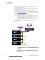
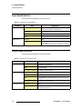
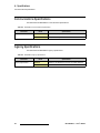
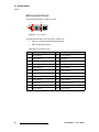
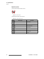
1
_äÉåÇmolJff rëÉêÛë=dìáÇÉ • • Manual # 26-0507000-00 Revision A _äÉåÇmolJff=√=rëÉêÛë=dìáÇÉ `çéóêáÖÜí © Barco, Inc. August 7, 2006 All rights reserved. No part of this document may be copied, reproduced or translated. It shall not otherwise be recorded, transmitted or stored in a retrieval system without the prior written consent of Barco. kçíáÅÉ Barco provides this manual “as is” without warranty of any kind, either expressed or implied, including but not limited to the implied warranties or merchantability and fitness for a particular purpose. Barco may make improvements and/or changes to the product(s) and/ or the program(s) described in this publication at any time without notice. This publication could contain technical inaccuracies or typographical errors. Changes are periodically made to the information in this publication; these changes are incorporated in new editions of this publication. cÉÇÉê~ä=`çããìåáÅ~íáçåë=`çããáëëáçå=Ec``F=pí~íÉãÉåí This equipment has been tested and found to comply with the limits for a class A digital device, pursuant to Part 15 of the FCC rules. These limits are designed to provide reasonable protection against harmful interference when the equipment is operated in a commercial environment. This equipment generates, uses, and can radiate radio frequency energy and, if not installed and used in accordance with the instruction manual, may cause harmful interference to radio communications. Operation of this equipment in a residential area may cause harmful interference, in which case the user will be responsible for correcting any interference. dì~ê~åíÉÉ=~åÇ=`çãéÉåë~íáçå Barco provides a guarantee relating to perfect manufacturing as part of the legally stipulated terms of guarantee. On receipt, the purchaser must immediately inspect all delivered goods for damage incurred during transport, as well as for material and manufacturing faults Barco must be informed immediately in writing of any complaints. The period of guarantee begins on the date of transfer of risks, in the case of special systems and software on the date of commissioning, at latest 30 days after the transfer of risks. In the event of justified notice of compliant, Barco can repair the fault or provide a replacement at its own discretion within an appropriate period. If this measure proves to be impossible or unsuccessful, the purchaser can demand a reduction in the purchase price or cancellation of the contract. All other claims, in particular those relating to compensation for direct or indirect damage, and also damage attributed to the operation of software as well as to other services provided by Barco, being a component of the system or independent service, will be deemed invalid provided the damage is not proven to be attributed to the absence of properties guaranteed in writing or due to the intent or gross negligence or part of Barco. If the purchaser or a third party carries out modifications or repairs on goods delivered by Barco, or if the goods are handled incorrectly, in particular if the systems are commissioned operated incorrectly or if, after the transfer of risks, the goods are subject to influences not 2 BlendPRO-II • User’s Guide agreed upon in the contract, all guarantee claims of the purchaser will be rendered invalid. Not included in the guarantee coverage are system failures which are attributed to programs or special electronic circuitry provided by the purchaser, e.g. interfaces. Normal wear as well as normal maintenance are not subject to the guarantee provided by Barco either. The environmental conditions as well as the servicing and maintenance regulations specified in this manual must be complied with by the customer. qê~ÇÉã~êâë Brand and product names mentioned in this manual may be trademarks, registered trademarks or copyrights of their respective holders. All brand and product names mentioned in this manual serve as comments or examples and are not to be understood as advertising for the products or their manufactures. `çãé~åó=^ÇÇêÉëë Barco Media and Entertainment 11101 Trade Center Drive Rancho Cordova, California 95670 USA • • • Phone: (916) 859-2500 Fax: (916) 859-2515 Websites: ~ ~ www.folsom.com www.events.barco.com Barco N.V. Noordlaan 5 8520 Kuurne BELGIUM • • • Phone: +32 56.36.82.11 Fax: +32 56.35.16.51 Website: www.barco.com BlendPRO-II • User’s Guide 3 léÉê~íçêë=p~ÑÉíó=pìãã~êó The general safety information in this summary is for operating personnel. aç=kçí=oÉãçîÉ=`çîÉêë=çê=m~åÉäë There are no user-serviceable parts within the unit. Removal of the top cover will expose dangerous voltages. To avoid personal injury, do not remove the top cover. Do not operate the unit without the cover installed. mçïÉê=pçìêÅÉ This product is intended to operate from a power source that will not apply more than 230 volts rms between the supply conductors or between both supply conductor and ground. A protective ground connection by way of grounding conductor in the power cord is essential for safe operation. dêçìåÇáåÖ=íÜÉ=mêçÇìÅí This product is grounded through the grounding conductor of the power cord. To avoid electrical shock, plug the power cord into a properly wired receptacle before connecting to the product input or output terminals. A protective-ground connection by way of the grounding conductor in the power cord is essential for safe operation. rëÉ=íÜÉ=mêçéÉê=mçïÉê=`çêÇ Use only the power cord and connector specified for your product. Use only a power cord that is in good condition. Refer cord and connector changes to qualified service personnel. aç=kçí=léÉê~íÉ=áå=bñéäçëáîÉ=^íãçëéÜÉêÉë To avoid explosion, do not operate this product in an explosive atmosphere. 4 BlendPRO-II • User’s Guide qÉêãë=få=qÜáë=j~åì~ä=~åÇ=bèìáéãÉåí=j~êâáåÖ= t^okfkd Highlights an operating procedure, practice, condition, statement, etc., which, if not strictly observed, could result in injury to or death of personnel. Note Highlights an essential operating procedure, condition or statement. `^rqflk The exclamation point within an equilateral triangle is intended to alert the user to the presence of important operating and maintenance (servicing) instructions in the literature accompanying the appliance. ^sboqfppbjbkq> Le point d´exclamation dans un triangle equilatéral signale à alerter l´utilisateur qu´il y a des instructions d´operation et d´entretien tres importantes dans la litérature qui accompagne l´appareil. slopf`eq Ein Ausrufungszeichen innerhalb eines gleichwinkeligen Dreiecks dient dazu, den Benutzer auf wichtige Bedienungs-und Wartungsanweisungen in der Dem Great beiliegenden Literatur aufmerksam zu machen. BlendPRO-II • User’s Guide 5 `Ü~åÖÉ=eáëíçêó The table below lists the changes to the BlendPRO-II User’s Guide. Table 0-1. Change History Rev A 6 Date 8/7/06 ECO # 1674 Description BlendPRO-II User’s Guide Approved By M. Lettau BlendPRO-II • User’s Guide q~ÄäÉ=çÑ=`çåíÉåíë `Ü~éíÉê=N fåíêçÇìÅíáçå =K=K=K=K=K=K=K=K=K=K=K=K=K=K=K=K=K=K=K=K=K=K=K=K=K=K=K=K=K=K=K=K=K=K=K=K=K=K=K=K=K=K= V In This Chapter . . . . . . . . . . . . . . . . . . . . . . . . . . . . . . . . . . . . . . . . . . . . . . . . . 9 Chapter Structure . . . . . . . . . . . . . . . . . . . . . . . . . . . . . . . . . . . . . . . . . . . . . . 10 How to Use This Guide. . . . . . . . . . . . . . . . . . . . . . . . . . . . . . . . . . . . . . . . . . 11 Navigating . . . . . . . . . . . . . . . . . . . . . . . . . . . . . . . . . . . . . . . . . . . . . . 11 Table of Contents and Index . . . . . . . . . . . . . . . . . . . . . . . . . . . . . . . . 11 General Operations . . . . . . . . . . . . . . . . . . . . . . . . . . . . . . . . . . . . . . . 11 Conventions . . . . . . . . . . . . . . . . . . . . . . . . . . . . . . . . . . . . . . . . . . . . . . . . . . 11 About the BlendPRO-II . . . . . . . . . . . . . . . . . . . . . . . . . . . . . . . . . . . . . . . . . . 12 Features . . . . . . . . . . . . . . . . . . . . . . . . . . . . . . . . . . . . . . . . . . . . . . . . . . . . . 13 Application Questions . . . . . . . . . . . . . . . . . . . . . . . . . . . . . . . . . . . . . . . . . . . 13 Connectivity Diagram . . . . . . . . . . . . . . . . . . . . . . . . . . . . . . . . . . . . . . . . . . . 14 `Ü~éíÉê=O e~êÇï~êÉ=lêáÉåí~íáçå =K=K=K=K=K=K=K=K=K=K=K=K=K=K=K=K=K=K=K=K=K=K=K=K=K=K=K=K=K=K=K=K=NR In This Chapter . . . . . . . . . . . . . . . . . . . . . . . . . . . . . . . . . . . . . . . . . . . . . . . . 15 BlendPRO-II Front Panel . . . . . . . . . . . . . . . . . . . . . . . . . . . . . . . . . . . . . . . . 16 BlendPRO-II Rear Panel . . . . . . . . . . . . . . . . . . . . . . . . . . . . . . . . . . . . . . . . 17 `Ü~éíÉê=P fåëí~ää~íáçå =K=K=K=K=K=K=K=K=K=K=K=K=K=K=K=K=K=K=K=K=K=K=K=K=K=K=K=K=K=K=K=K=K=K=K=K=K=K=K=K=K=K=ON In This Chapter . . . . . . . . . . . . . . . . . . . . . . . . . . . . . . . . . . . . . . . . . . . . . . . . Safety Precautions . . . . . . . . . . . . . . . . . . . . . . . . . . . . . . . . . . . . . . . . . . . . . Unpacking and Inspection . . . . . . . . . . . . . . . . . . . . . . . . . . . . . . . . . . . . . . . Site Preparation . . . . . . . . . . . . . . . . . . . . . . . . . . . . . . . . . . . . . . . . . . . . . . . Cable and Adapter Information. . . . . . . . . . . . . . . . . . . . . . . . . . . . . . . . . . . . Rack-Mount Installation . . . . . . . . . . . . . . . . . . . . . . . . . . . . . . . . . . . . . . . . . Power Installation . . . . . . . . . . . . . . . . . . . . . . . . . . . . . . . . . . . . . . . . . . . . . . Power Cord/Line Voltage Selection . . . . . . . . . . . . . . . . . . . . . . . . . . . Signal Installation . . . . . . . . . . . . . . . . . . . . . . . . . . . . . . . . . . . . . . . . . . . . . . ScreenPRO-II Genlock Termination . . . . . . . . . . . . . . . . . . . . . . . . . . Format Connection Table . . . . . . . . . . . . . . . . . . . . . . . . . . . . . . . . . . . . . . . . `Ü~éíÉê=Q 21 22 22 22 22 23 23 24 25 27 28 léÉê~íáçåK=K=K=K=K=K=K=K=K=K=K=K=K=K=K=K=K=K=K=K=K=K=K=K=K=K=K=K=K=K=K=K=K=K=K=K=K=K=K=K=K=K=K=K=OV In This Chapter . . . . . . . . . . . . . . . . . . . . . . . . . . . . . . . . . . . . . . . . . . . . . . . . 29 Control Overview . . . . . . . . . . . . . . . . . . . . . . . . . . . . . . . . . . . . . . . . . . . . . . 30 `Ü~éíÉê=R réÖê~ÇáåÖ=pçÑíï~êÉK=K=K=K=K=K=K=K=K=K=K=K=K=K=K=K=K=K=K=K=K=K=K=K=K=K=K=K=K=K=K=K=K=K=PN In This Chapter . . . . . . . . . . . . . . . . . . . . . . . . . . . . . . . . . . . . . . . . . . . . . . . . 31 Software Upgrade Overview. . . . . . . . . . . . . . . . . . . . . . . . . . . . . . . . . . . . . . 32 BlendPRO-II • User’s Guide 7 Table of Contents ^ééÉåÇáñ=^= péÉÅáÑáÅ~íáçåëK=K=K=K=K=K=K=K=K=K=K=K=K=K=K=K=K=K=K=K=K=K=K=K=K=K=K=K=K=K=K=K=K=K=K=K=K=K=K=K=PP In This Appendix. . . . . . . . . . . . . . . . . . . . . . . . . . . . . . . . . . . . . . . . . . . . . . . Input Specifications . . . . . . . . . . . . . . . . . . . . . . . . . . . . . . . . . . . . . . . . . . . . Output Specifications . . . . . . . . . . . . . . . . . . . . . . . . . . . . . . . . . . . . . . . . . . . User Control Specifications . . . . . . . . . . . . . . . . . . . . . . . . . . . . . . . . . . . . . . Physical and Electrical Specifications . . . . . . . . . . . . . . . . . . . . . . . . . . . . . . Communications Specifications . . . . . . . . . . . . . . . . . . . . . . . . . . . . . . . . . . . Agency Specifications . . . . . . . . . . . . . . . . . . . . . . . . . . . . . . . . . . . . . . . . . . Pinouts . . . . . . . . . . . . . . . . . . . . . . . . . . . . . . . . . . . . . . . . . . . . . . . . . . . . . . Analog 15-pin D Connector . . . . . . . . . . . . . . . . . . . . . . . . . . . . . . . . . DVI Connector Pinouts . . . . . . . . . . . . . . . . . . . . . . . . . . . . . . . . . . . . Ethernet Connector . . . . . . . . . . . . . . . . . . . . . . . . . . . . . . . . . . . . . . . Serial Connector . . . . . . . . . . . . . . . . . . . . . . . . . . . . . . . . . . . . . . . . . ^ééÉåÇáñ=_= `çåí~Åí=fåÑçêã~íáçå=K=K=K=K=K=K=K=K=K=K=K=K=K=K=K=K=K=K=K=K=K=K=K=K=K=K=K=K=K=K=K=K=K=K=QN In This Appendix. . . . . . . . . . . . . . . . . . . . . . . . . . . . . . . . . . . . . . . . . . . . . . . Warranty . . . . . . . . . . . . . . . . . . . . . . . . . . . . . . . . . . . . . . . . . . . . . . . . . . . . . Return Material Authorization (RMA) . . . . . . . . . . . . . . . . . . . . . . . . . . . . . . . Contact Information . . . . . . . . . . . . . . . . . . . . . . . . . . . . . . . . . . . . . . . . . . . . fåÇÉñ 8 33 34 34 35 35 36 36 37 37 38 39 40 41 41 41 42 =K=K=K=K=K=K=K=K=K=K=K=K=K=K=K=K=K=K=K=K=K=K=K=K=K=K=K=K=K=K=K=K=K=K=K=K=K=K=K=K=K=K=K=K=K=K=K=K=K=K=K=K=K=QP BlendPRO-II • User’s Guide NK==fåíêçÇìÅíáçå få=qÜáë=`Ü~éíÉê This chapter is designed to introduce you to the BlendPRO-II User’s Guide. Areas to be covered are: • • • • • • • Chapter Structure How to Use This Guide Conventions About the BlendPRO-II Features Application Questions Connectivity Diagram BlendPRO-II • User’s Guide 9 NK==fåíêçÇìÅíáçå Chapter Structure `Ü~éíÉê=píêìÅíìêÉ The following chapters provide instructions for all aspects of BlendPRO-II operations: 10 • Chapter 1, “Introduction” provides a system overview, a list of features, and a system connectivity diagram. • Chapter 2, “Hardware Orientation” on page 15 provides detailed diagrams of the system’s front and rear panels. • Chapter 3, “Installation” on page 21 provides comprehensive system installation instructions. • • Chapter 4, “Operation” on page 29 provides system operating instructions. • • Appendix A, “Specifications” on page 33 lists the BlendPRO-II’s specifications. Chapter 5, “Upgrading Software” on page 31 outlines procedures for upgrading system software components. Appendix B, “Contact Information” on page 41 lists important Barco contact, RMA, warranty and technical support details. BlendPRO-II • User’s Guide NK==fåíêçÇìÅíáçå How to Use This Guide eçï=íç=rëÉ=qÜáë=dìáÇÉ Following are important tips for streamlining your use of this User’s Guide in its electronic “PDF” form. k~îáÖ~íáåÖ Use Acrobat Reader’s “bookmarks” to navigate to the desired location. All chapter files have the same bookmark structure for instant navigation to any section. Please note: • • Extensive hyperlinks are provided within the chapters. • Use the “Previous Page” and “Next Page” buttons to go to the previous or next page within a file. • Use Acrobat’s extensive search capabilities, such as the “Find” tool and “Search Index” tool to perform comprehensive searches as required. Use Acrobat’s “Go to Previous View” and “Return to Next View” buttons to trace your complete navigational path. q~ÄäÉ=çÑ=`çåíÉåíë=~åÇ=fåÇÉñ Use the Table of Contents bookmarks to navigate a desired topic. Click any item to instantly jump to that section of the guide. You can also use the Index to jump to specific topics within a chapter. Each page number in the Index is a hyperlink. dÉåÉê~ä=léÉê~íáçåë To ensure trouble-free operation, please follow all procedures in the Installation and Operation sections of this manual. • Refer to Chapter 3, “Installation” on page 21 and Chapter 4, “Operation” on page 29 for details. • Should you have any questions regarding the installation or operation of the BlendPRO-II system, please consult with the factory. Refer to Appendix B, “Contact Information” on page 41 for information. = `çåîÉåíáçåë= The following conventions are used throughout this guide: • • • The symbol denotes an operations procedure. The symbol S denotes an example. Entries written in bold-face capital letters denote physical buttons or chassis connectors. S Use the GENLOCK connector to ... BlendPRO-II • User’s Guide 11 NK==fåíêçÇìÅíáçå About the BlendPRO-II ^Äçìí=íÜÉ=_äÉåÇmolJff The BlendPRO-II is a “presentation” system component that allows standard highresolution images (as generated by multiple ScreenPro-II units) to be displayed in a multiprojector widescreen format. The system completely eliminates the need to “pre-overlap” source material during the content creation phase of your presentation. BlendPRO-II receives signals from up to four ScreenPro-II units (via high-resolution DVI connections) and processes the video for display in multi-projector widescreen format. Processing includes: • • Data doubling to generate overlapped projected regions. Edge-feathering of the overlapped images. The amount of data overlap and edge-feathering parameters are user-programmable. BlendPRO-II supports simultaneous digital and analog output signals to separate DVI and HD-15 connectors. Refer to the “Connectivity Diagram” section on page 14 for an illustration of a typical BlendPRO-II application. In order to synchronize the ScreenPRO-II units for use in a widescreen projection application (in conjunction with the ScreenPRO-II Controller), BlendPRO-II provides a Widescreen Lock output which is used to lock each ScreenPRO-II unit to one common master timing signal. In addition, this signal supports real-time command synchronization between all connected ScreenPRO-II units, which in turn guarantees that all time-critical functions (such as T-Bar commands) occur synchronously across all units. Please note the following important points: 12 • For applications where it is desirable to frame lock the system’s widescreen output to a master house sync (such as an NTSC or PAL black burst signal), a Genlock input BNC is provided. • • • • • • The unit frame locks to CSYNC (composite bi- or tri-level) sync signals. BlendPRO-II supports only progressive video formats. The unit does not provide scaling or frame rate conversion of input sources. Output timing matches input timing. Video delay through the BlendPRO-II is 6 video lines or less. DVI outputs from ScreenPRO-II must be H & V locked, using the “Widescreen Lock” output from BlendPRO-II. BlendPRO-II • User’s Guide NK==fåíêçÇìÅíáçå Features cÉ~íìêÉë The BlendPRO-II system includes the following advanced features: • • • • • • • • Blending of up to four ScreenPro-II units. User programmable data doubling, edge-feathering, and output gamma. Simultaneous digital and analog outputs. Real-time command synchronization between all connected ScreenPRO-II units. Separate Genlock and Widescreen Lock connections (BNC). Progressive video format support. Low video delay, less than 6 lines. Integral test pattern generator. Important All system setup and control is performed via Ethernet, through the ScreenPRO-II Controller. ^ééäáÅ~íáçå=nìÉëíáçåë At Barco, we take pride in offering unique solutions to demanding technical problems. If you have application questions, require further information or would like to discuss your application requirements in more detail, please call (916) 859-2500. Our Customer Support Engineers will be happy to supply you with the support you need. Refer to Appendix B, “Contact Information” on page 41 for details. BlendPRO-II • User’s Guide 13 NK==fåíêçÇìÅíáçå Connectivity Diagram `çååÉÅíáîáíó=aá~Öê~ã The figure below illustrates a sample connectivity diagram: X4 Widescreen Blend Preview 1 Preview 2 Preview 3 Preview 4 Program 1 Program 2 Analog Program 3 Program 4 Analog ScreenPRO-II ID #1 ScreenPRO-II ID #2 DVI Out or Analog Out BlendPRO-II DVI In Widescreen Lock (Required) Genlock In (Optional) ScreenPRO-II Controller ScreenPRO-II ID #3 ScreenPRO-II ID #4 Switch Ethernet Figure 1-1. Typical BlendPRO-II Application (sample) Please note the following points regarding the system: 14 • • The maximum system configuration of four ScreenPRO-II units is shown. • DVI signals connect the ScreenPRO-II outputs to BlendPRO-II, and the BlendPRO-II to each projector input. • • Analog connectivity from each ScreenPRO-II is used for monitoring. Ethernet connects the BlendPRO-II to all ScreenPRO-II units and the ScreenPRO-II Controller, via a network switch. The Widescreen Lock output from BlendPRO-II is used to lock each ScreenPRO-II system. These connections are required. BlendPRO-II • User’s Guide OK==e~êÇï~êÉ=lêáÉåí~íáçå få=qÜáë=`Ü~éíÉê This chapter provides detailed diagrams of the system’s front and rear panels. The following topics are discussed: • • BlendPRO-II Front Panel BlendPRO-II Rear Panel BlendPRO-II • User’s Guide 15 2. Hardware Orientation BlendPRO-II Front Panel _äÉåÇmolJff=cêçåí=m~åÉä The figure below illustrates the BlendPRO-II front panel: Visibly yours BLENDPRO II Figure 2-1. BlendPRO-II Front Panel There are no user controls on the front panel of the BlendPRO-II chassis. All operating procedures are performed through the ScreenPRO-II Controller. Refer to Chapter 4, “Operation” on page 29 for additional details. 16 BlendPRO-II • User’s Guide 2. Hardware Orientation BlendPRO-II Rear Panel _äÉåÇmolJff=oÉ~ê=m~åÉä The figure below illustrates the BlendPRO-II rear panel: 1 2 3 4 SERIAL GENLOCK IN WIDESCREEN LOCK OUT OUTPUTS 1 2 3 4 1 2 3 4 ETHERNET INPUTS 1 2 3 4 100-240 V 50-60 Hz 2.3 A 5 6 7 Figure 2-1. BlendPRO-II Rear Panel 1) Genlock In 5) Inputs Section 2) Widescreen Lock Out 6) Outputs Section 3) Serial Port 7) Ethernet Port 4) AC Connector Following are descriptions of each rear panel connector and section: 1) Genlock In One BNC connector is provided for a Genlock Input, which can be used to lock BlendPRO-II and its associated ScreenPro-II inputs to an external source if desired. Please note: 2) ~ ~ BlendPRO-II can genlock to Composite bi or tri-level syncs. ~ Because BlendPRO-II does not contain a loop-through connector, the incoming sync will be terminated to 75 Ohms. Similarly, black burst type syncs can be used within the limitations of the BlendPRO-II input resolutions. Widescreen Lock Out One BNC connector is provided for a Widescreen Lock Output, which is required to supply H and V sync locking information to each ScreenPro-II GENLOCK input, as well as communicate various widescreen synchronization commands via a proprietary interface. Important BlendPRO-II • User’s Guide This connector is not a loop-through, and can only be used with BlendPRO-II and ScreenPRO-II systems. 17 2. Hardware Orientation BlendPRO-II Rear Panel 3) Serial Port One 9-pin D connector is provided for RS-232 serial communications with BlendPRO-II, typically for diagnostic purposes. The port is configured as a DCE, 115K Baud, 8 data bit, 1 stop bit, and no parity bits. The port can be connected to a standard PC serial port with a straight through DB-9 to DB-9 cable. In Appendix A, refer to the “Serial Connector” section on page 40 for pinouts. 4) AC Connector One AC Connector is provided for connecting BlendPRO-II to your facility’s AC power source. The integral switch turns the chassis on and off. 5) Inputs Section The figure below illustrates the Inputs Section: INPUTS 1 2 3 4 Figure 2-2. BlendPRO-II Inputs Section The Inputs Section includes four DVI digital inputs per DDWG 1.0 specifications. All four are DVI-D (digital, single link, receptacle) using DVI-I connectors to allow flexible cabling choices. Please note: ~ Each input accepts DVI progressive RGB signals with a pixel clock speed from 25 - 162MHz (1600x1200x60Hz). ~ Each input must be of the same resolution and H/V locked together. In Appendix A, refer to the “DVI Connector Pinouts” section on page 38 for pinout details. 18 BlendPRO-II • User’s Guide 2. Hardware Orientation BlendPRO-II Rear Panel 6) Outputs Section The figure below illustrates the Outputs Section: OUTPUTS 1 2 3 4 1 2 3 4 Figure 2-3. BlendPRO-II Outputs Section The Outputs Section includes four digital and four analog outputs: ~ DVI — the four DVI digital outputs are per DDWG 1.0 specifications. All four are DVI-D (digital, single link, receptacle) using DVI-I connectors. The DVI outputs are of the same resolution as the inputs. In Appendix A, refer to the “DVI Connector Pinouts” section on page 38 for pinout details. ~ Analog — the four HD-15 analog outputs provide progressive RGB. Analog syncs can be configured for 5 wire (RGBHV), 4 wire (RGB composite sync) or 3 wire (sync on green) operation. Please note: • Video components are driven at 700mV peak amplitude (1V for SOG) at 75 Ohm terminations. • Sync components (4 and 5 wire) are driven at TTL compatible levels at 75 Ohm terminations. • The analog outputs is driven at the same resolution and in sync with the DVI outputs. • Data is identical to the data on the DVI outputs, except that the analog circuits are 10-bit, and thus preserve the 10-bit result of the data doubling and feathering operations. In Appendix A, refer to the “Analog 15-pin D Connector” section on page 37 for pinout details. 7) Ethernet Port One RJ-45 (Neutrik) connector is provided for Ethernet communications with BlendPRO-II. Ethernet is the primary means of controlling the BlendPRO-II. Please note: ~ ~ The Ethernet port is 10/100 Mbit auto-sensing capable. The port is primarily configured to run as a DHCP client, although static IP can be used if desired. In Appendix A, refer to the “Ethernet Connector” section on page 39 for pinouts. BlendPRO-II • User’s Guide 19 2. Hardware Orientation BlendPRO-II Rear Panel 20 BlendPRO-II • User’s Guide PK==fåëí~ää~íáçå få=qÜáë=`Ü~éíÉê This chapter provides detailed instructions for installing the BlendPRO-II hardware. The following topics are discussed: • • • • • • • • Safety Precautions Unpacking and Inspection Site Preparation Cable and Adapter Information Rack-Mount Installation Power Installation Signal Installation Format Connection Table BlendPRO-II • User’s Guide 21 3. Installation Safety Precautions p~ÑÉíó=mêÉÅ~ìíáçåë= For all BlendPRO-II installation procedures, observe the following important safety and handling rules to avoid damage to yourself and the equipment: • To protect users from electric shock, ensure that the power supplies for each unit connect to earth via the ground wire provided in the AC power Cord. • The AC Socket-outlet should be installed near the equipment and be easily accessible. råé~ÅâáåÖ=~åÇ=fåëéÉÅíáçå= Before opening the BlendPRO-II box, inspect it for damage. If you find any damage, notify the shipping carrier immediately for all claims adjustments. As you open the box, compare its contents against the packing slip. If you find any shortages, contact your Barco sales representative. Once you have removed all the components from their packaging and checked that all the listed components are present, visually inspect each unit to ensure there was no damage during shipping. If there is damage, notify the shipping carrier immediately for all claims adjustments. páíÉ=mêÉé~ê~íáçå= The environment in which you install your BlendPRO-II(s) should be clean, properly lit, free from static, and have adequate power, ventilation, and space for all components. `~ÄäÉ=~åÇ=^Ç~éíÉê=fåÑçêã~íáçå The table below provides information regarding supplied cables and adapters: Table 3-1. BlendPRO-II System Cables and Adapters Cable / Adapter AC Power Cord 22 Description 7 foot, 10A Quantity 1 BlendPRO-II • User’s Guide 3. Installation Rack-Mount Installation o~ÅâJjçìåí=fåëí~ää~íáçå BlendPRO-II units are designed to be rack mounted and are supplied with front rack-mount hardware. Please note the following important points: • Rear rack-mount brackets are available as a kit, and are recommended for use when units are mounted in transit cases. • When rack mounting the unit, remember that the maximum ambient operating temperature for the unit is 40 degrees C. • Leave sufficient front and rear space to make sure that the airflow through the fan and vent holes is not restricted. • When installing equipment into a rack, distribute the units evenly to prevent hazardous conditions that may be created by uneven weight distribution. • • • Connect the unit only to a properly rated supply circuit. • Install the lower of the two mounting holes first. Reliable grounding (earthing) of rack-mounted equipment should be maintained. Rack mount the unit from the front rack ears using four rack screws (not supplied). Rack threads may be metric or otherwise — depending upon the rack type. mçïÉê=fåëí~ää~íáçå Use the following steps to install power to the BlendPRO-II: 1. Connect an AC power cord to the AC Power Connector on the rear of the BlendPRO-II, and then to an AC outlet. 2. Connect AC Power cords (or AC adapters) to all peripheral equipment, such as ScreenPRO-II systems, monitors and projectors. Please note: ~ ~ BlendPRO-II • User’s Guide Connect each unit only to a properly rated supply circuit. Reliable grounding of rack-mounted equipment should be maintained. 23 3. Installation Power Installation mçïÉê=`çêÇLiáåÉ=sçäí~ÖÉ=pÉäÉÅíáçå BlendPRO-II is rated to operate with the following supplies: • • Input Power: 100-240 VAC, 47-63 Hz Power Consumption: 80 watts maximum BlendPRO-II performs line voltage selection automatically, and no user controls are required. The AC power cords must be accessible so that they can be removed during field servicing. Warning When the BlendPRO-II is used in the 230-volt mode, a UL listed line cord rated for 250 volts at 15 amps must be used and must conform to IEC-227 and IEC-245 standards. This cord will be fitted with a tandem prong-type plug. The rear panel ON/OFF switch does not disconnect the unit from input AC power. To facilitate disconnection of AC power, the power cord must be connected to an accessible outlet near the unit. Building Branch Circuit Protection: For 115 V use 20 A, for 230 V use 8 A. Figure 3-1. Tandem Prong-type Plug Avertissement Warnung 24 La choix de la ligne de voltage se réalise automatiquement par le BlendPRO-II Transformateur Graphique. On n'a pas besoin du controller usager pour la choix de la ligne de voltage. Das BlendPRO-II gerät mu beim Anschlu an 240V ~ mit einer vom VDE auf 250V/10A geprüften Netzleitung mit einem Schukostecker ausgestattet sein. BlendPRO-II • User’s Guide 3. Installation Signal Installation páÖå~ä=fåëí~ää~íáçå The figure below illustrates a sample BlendPRO-II system, which uses the maximum four ScreenPRO-II units. Use this figure for reference during the signal installation process. If required, refer to the “BlendPRO-II Rear Panel” section on page 17 in Chapter 2 for details on all rear panel connectors. X4 Widescreen Blend Preview 1 Preview 2 Preview 3 Preview 4 Program 1 Program 2 Analog Program 3 Program 4 Analog ScreenPRO-II ID #1 ScreenPRO-II ID #2 DVI Out or Analog Out BlendPRO-II DVI In Widescreen Lock (Required) Genlock In (Optional) ScreenPRO-II Controller ScreenPRO-II ID #3 ScreenPRO-II ID #4 Switch Ethernet Figure 3-2. BlendPRO-II System Diagram (sample) Use the following steps to install signals to/from the BlendPRO-II: 1. Connect your Program/Preview monitoring as required, using the analog outputs from your selected ScreenPRO-II units. The units’ DVI outputs must be reserved for connection to BlendPRO-II. 2. Connect Ethernet communications to all ScreenPRO-II units, to the BlendPRO-II, and to the ScreenPRO-II Controller. A totally “local” network is recommended, BlendPRO-II • User’s Guide 25 3. Installation Signal Installation without IP connections to the outside world. Use standard Ethernet cables in conjunction with an Ethernet switch. 3. Connect a DVI output from each ScreenPRO-II unit (up to the maximum of 4) to the DVI inputs on BlendPRO-II. 4. Connect the DVI or analog outputs from BlendPRO-II to the inputs of your selected projectors (up to the maximum of 4). If you are using the analog outputs, refer to the “Format Connection Table” section on page 28 for connection details using a customer supplied breakout cable. 5. External Genlock connections to BlendPRO-II are optional. 6. a. If desired (particularly if you will be using synchronous cameras), use a BNC cable to connect a PAL or NTSC black burst (or a composite sync) signal to the GENLOCK IN connector on BlendPRO-II. b. Do not connect an external Genlock signal to any ScreenPRO-II unit in your system. Widescreen Lock connections are mandatory. Use the figure below for reference: GENLOCK IN IN LOOP WIDESCREEN LOCK OUT Termination BlendPRO-II GENLOCK ScreenPRO-II ID #1 In Loop Widescreen Lock Genlock Un-terminated ScreenPRO-II ID #2 In Loop Un-terminated ScreenPRO-II ID #3 In Loop Un-terminated ScreenPRO-II ID #4 In Terminated Figure 3-3. BlendPRO-II Widescreen Lock Connections (sample) 26 a. Connect a BNC cable from BlendPRO-II’s WIDESCREEN LOCK output to the GENLOCK IN connector on the ScreenPRO-II unit with the lowest numbered ID. b. Connect the first ScreenPRO-II’s GENLOCK LOOP connector to the GENLOCK IN connector on the ScreenPRO-II unit with the next highest numbered ID. BlendPRO-II • User’s Guide 3. Installation Signal Installation c. (If your system includes three ScreenPRO-IIs) — Connect the second ScreenPRO-II’s GENLOCK LOOP connector to the GENLOCK IN connector on the ScreenPRO-II with the next highest numbered ID. d. (If your system includes four ScreenPRO-IIs) — Connect the third ScreenPRO-II’s GENLOCK LOOP connector to the GENLOCK IN connector on the ScreenPRO-II unit with the highest numbered ID. e. Set the Termination Switch for all ScreenPRO-IIs in your system: • For all ScreenPRO-IIs except the last one in the chain, ensure that the ScreenPRO-II is un-terminated (HI-Z). Refer to the “ScreenPRO-II Genlock Termination” section on page 27 for details. • On the last unit in the chain (only), ensure that the ScreenPRO-II is terminated (75-OHM). Please continue with system setup, menu orientation and operations, as outlined in Chapter 4, “Operation” on page 29. pÅêÉÉåmolJff=dÉåäçÅâ=qÉêãáå~íáçå On the rear of each ScreenPRO-II chassis, one recessed Termination Switch is provided for genlock termination (adjacent to the Genlock Loop connector). • Terminated — when the switch is pushed in, the connection is terminated (75 Ohms). • Un-terminated — when the switch is out, the connection is un-terminated. If a particular ScreenPRO-II chassis is the last device in a reference video chain, ensure that the Termination Switch is pushed in. If a particular ScreenPRO-II chassis is in the middle of a reference chain, ensure that the Termination Switch is out. BlendPRO-II • User’s Guide 27 3. Installation Format Connection Table cçêã~í=`çååÉÅíáçå=q~ÄäÉ Use the following table to connect BlendPRO-II’s analog RGB output to various analog projector inputs (3 wire, 4 wire and 5 wire). Using a customer supplied VGA to 5 x BNC breakout cable, multiple combinations are possible. Cells with checks denote the connections required for the indicated format. Note For RGB with H and V sync, use the VGA connector directly. Table 3-2. Analog Output Combinations using Breakout Cable Breakout Cable Wire Color RGB Sync on Green RGB Comp Sync RGB Separate H V R 3 3 3 G 3 3 3 B 3 3 3 3 3 H Sync V Sync 3 Please contact Barco Technical Support for information on obtaining breakout cables. In Appendix B, refer to the “Contact Information” section on page 42 for details. 28 BlendPRO-II • User’s Guide QK==léÉê~íáçå få=qÜáë=`Ü~éíÉê This chapter provides detailed operating instructions for the BlendPRO-II. The following topics are discussed: • Control Overview BlendPRO-II • User’s Guide 29 4. Operation Control Overview `çåíêçä=lîÉêîáÉï All BlendPRO-II setup and operating procedures are performed through the ScreenPRO-II Controller. There are no user controls on the BlendPRO-II unit itself. Important 30 Refer to the “ScreenPRO-II Controller User’s Guide” for complete setup and operating procedures. BlendPRO-II • User’s Guide RK==réÖê~ÇáåÖ=pçÑíï~êÉ få=qÜáë=`Ü~éíÉê This chapter provides instructions for upgrading BlendPRO-II system software. The following topics are discussed: • Software Upgrade Overview BlendPRO-II • User’s Guide 31 5. Upgrading Software Software Upgrade Overview pçÑíï~êÉ=réÖê~ÇÉ=lîÉêîáÉï All software upgrade procedures are performed through the ScreenPRO-II Controller. There are no user controls provided on the BlendPRO-II unit itself. Please note: • Code compatibility — when the ScreenPRO-II Controller connects to the individual ScreenPRO-II units and to BlendPRO-II, it automatically checks the compatibility of the code versions. If the ScreenPRO-II Controller’s code version matches that of the ScreenPRO-II units and BlendPRO-II, the Controller’s System Status Menu is shown — and you will not need to download code. ~ If the message “Checksum Mismatch” appears on the System Status Menu, you must download code. ~ If the ScreenPRO-II Controller’s code version is incompatible with the either the ScreenPRO-II units’ code version or the BlendPRO-II’s code version (or a combination of units), all buttons will flash on the Controller console. The System Status Menu is shown with the message “Please Upgrade.” Important 32 Refer to the “ScreenPRO-II Controller User’s Guide” for complete software upgrade procedures. BlendPRO-II • User’s Guide ^K==péÉÅáÑáÅ~íáçåë få=qÜáë=^ééÉåÇáñ This appendix provides detailed technical specifications for the BlendPRO-II. The following topics are discussed: • • • • • • • Input Specifications Output Specifications User Control Specifications Physical and Electrical Specifications Communications Specifications Agency Specifications Pinouts BlendPRO-II • User’s Guide 33 ^K==péÉÅáÑáÅ~íáçåë Input Specifications fåéìí=péÉÅáÑáÅ~íáçåë= The table below lists BlendPRO-II input specifications. Table A-1. BlendPRO-II Input Specifications Parameter Detail DVI Inputs 1 - 4 Genlock Input Specification Connector (4) DVI-D connectors (digital, single link, receptacle), each input per DDWG 1.0 specifications. Video Progressive RGB Clock Speed / Resolution 25 - 162MHz (1600x1200x60Hz) Lock All inputs must be of the same resolution and H/V locked. Connector BNC Signal Connects to master house sync, e.g., NTSC or PAL black burst. Also genlocks to CSYNC (composite bi- or tri-level) sync signals. lìíéìí=péÉÅáÑáÅ~íáçåë The table below lists BlendPRO-II output specifications. Table A-2. BlendPRO-II Output Specifications Parameter DVI Outputs 1 - 4 Analog Outputs 1 - 4 Widescreen Lock 34 Detail Specification Connector (4) DVI-D connectors (digital, single link, receptacle), each input per DDWG 1.0 specifications. Video Progressive RGB Clock Speed / Resolution 25 - 162MHz (1600x1200x60Hz) Connector (4) HD-15 connectors Video Progressive RGB Sync 5 wire (RGBHV), 4 wire (RGB composite sync) or 3 wire (sync on green) Clock Speed / Resolution 25 - 162MHz (1600x1200x60Hz) Connector BNC Signal Proprietary, supplies H and V sync locking information to each ScreenPro-II Genlock input BlendPRO-II • User’s Guide ^K==péÉÅáÑáÅ~íáçåë User Control Specifications rëÉê=`çåíêçä=péÉÅáÑáÅ~íáçåë The table below lists BlendPRO-II user control specifications. Table A-3. BlendPRO-II User Control Specifications Parameter Detail User Control Specification Operations No local controls provided. Setup All setup functions performed from ScreenPRO-II Controller. Remote control All control functions performed from ScreenPRO-II Controller. mÜóëáÅ~ä=~åÇ=bäÉÅíêáÅ~ä=péÉÅáÑáÅ~íáçåë= The table below lists BlendPRO-II physical and electrical specifications. Table A-4. BlendPRO-II Physical and Electrical Specifications Parameter Power Mechanical Detail Specification Connector Standard IEC, integral on/off switch Input Power 47-63 Hz, 100-240 VAC Power Consumption 80 watts maximum Chassis H: 3.50 inches (8.89 cm) W: 17.00 inches (43.18 cm) W: 19.00 inches (48.26 cm) with rackmount wings D: 15.00 inches (38.10 cm) Temperature 0-40 degrees C Humidity 0-95% non-condensing Mounting 2 RU rack mount (19 inch, using front and rear mounts) Weight 17.0 lbs (7.71 kg) Shipping Weight 22 lbs (9.97 kg) BlendPRO-II • User’s Guide 35 ^K==péÉÅáÑáÅ~íáçåë Communications Specifications `çããìåáÅ~íáçåë=péÉÅáÑáÅ~íáçåë= The table below lists BlendPRO-II communications specifications. Table A-5. BlendPRO-II Communications Specifications Parameter Communications Detail Specification RS-232 DB-9 Female, DCE, 115k Baud Ethernet RJ-45, 10/100 Mbps Autosense ^ÖÉåÅó=péÉÅáÑáÅ~íáçåë= The table below lists BlendPRO-II agency specifications. Table A-6. BlendPRO-II Agency Specifications Parameter Agency Specifications 36 Detail Specification EMI/EMC EN55103-1 E4, EN55103-2, FCC Part 15 Subpart B Class A Safety EN 60950 Class 1 BlendPRO-II • User’s Guide ^K==péÉÅáÑáÅ~íáçåë Pinouts máåçìíë= The following topics are discussed in this section: • • • • Analog 15-pin D Connector DVI Connector Pinouts Ethernet Connector Serial Connector ^å~äçÖ=NRJéáå=a=`çååÉÅíçê The figure below illustrates the analog 15-pin D connector: 5 1 10 6 15 11 Figure A-1. Analog 15-pin D Connector, chassis view The table below lists Analog 15-pin D connector pinouts. Table A-7. Analog 15-pin D Connector Pinouts Pin Signal Pin 1 Red 9 2 Green 10 3 Blue 11 Signal GND 4 12 5 13 H Sync or C Sync V Sync 6 Red return 14 7 Green return 15 8 Blue return BlendPRO-II • User’s Guide 37 ^K==péÉÅáÑáÅ~íáçåë Pinouts asf=`çååÉÅíçê=máåçìíë The figure below illustrates the DVI-I connector: 1 8 17 24 9 Figure A-2. DVI-I Connector The table below lists DVI-I Connector pinouts. Please note: • • T.M.D.S = Transition Minimized Differential Signal DDC = Display Data Channel Table A-8. DVI-I Connector Pinouts Pin Signal Signal 1 T.M.D.S. Data 2- 13 T.M.D.S. Data 3+ 2 T.M.D.S. Data 2+ 14 +5V Power 3 T.M.D.S. Data 2/4 Shield 15 ground (for +5V) 4 T.M.D.S. Data 4- 16 Hot Plug Detect 5 T.M.D.S. Data 4+ 17 T.M.D.S. Data 0- 6 DDC Clock 18 T.M.D.S. Data 0+ 7 DDC Data 19 T.M.D.S. Data 0/5 Shield 20 T.M.D.S. Data 5- 8 38 Pin 9 T.M.D.S. Data 1- 21 T.M.D.S. Data 5+ 10 T.M.D.S. Data 1+ 22 T.M.D.S. Clock Shield 11 T.M.D.S. Data 1/3 Shield 23 T.M.D.S. Clock + 12 T.M.D.S. Data 3- 24 T.M.D.S. Clock - BlendPRO-II • User’s Guide ^K==péÉÅáÑáÅ~íáçåë Pinouts bíÜÉêåÉí=`çååÉÅíçê The figure below illustrates the Ethernet connector: 1 8 Figure A-3. Ethernet Connector The table below lists Ethernet connector pinouts. Table A-9. Ethernet Connector Pinouts Pin Signal Wire Color 1 TX Data + White / Orange 2 TX Data - Orange 3 RX Data + White / Green 4 Blue 5 White / Blue 6 RX Data - Green 7 White / Brown 8 Brown BlendPRO-II • User’s Guide 39 ^K==péÉÅáÑáÅ~íáçåë Pinouts pÉêá~ä=`çååÉÅíçê The figure below illustrates the Serial connector: 5 1 9 6 Figure A-4. Serial Connector The table below lists Serial connector pinouts. Table A-10. Serial Connector Pinouts Pin 40 RS-232 Signal Description 1 CD Carrier Detect 2 RXD Received Data 3 TXD Transmitted Data 4 DTR Data Terminal Ready 5 GND Signal Ground 6 DSR Data Set Ready 7 RTS Request To Send 8 CTS Clear To Send 9 RI Unused BlendPRO-II • User’s Guide _K==`çåí~Åí=fåÑçêã~íáçå få=qÜáë=^ééÉåÇáñ The following topics are discussed in this Appendix: • • • Warranty Return Material Authorization (RMA) Contact Information t~êê~åíó All video products are designed and tested to the highest quality standards and are backed by a full 3-year parts and labor warranty. Warranties are effective upon delivery date to customer and are non-transferable. Barco warranties are only valid to the original purchaser/owner. Warranty related repairs include parts and labor, but do not include faults resulting from user negligence, special modifications, lightning strikes, abuse (drop/crush), and/or other unusual damages. The customer shall pay shipping charges when unit is returned for repair. Barco will cover shipping charges for return shipments to customers. oÉíìêå=j~íÉêá~ä=^ìíÜçêáò~íáçå=Eoj^F In the unlikely event that a product is required to return for repair, please call the following number and ask for a Sales Engineer to receive a Return Merchandise Authorization number (RMA). • (888) 414-7226 RMA Conditions are listed below: BlendPRO-II • User’s Guide a. Prior to returning any item, you must receive a Return Merchandise Authorization (RMA) number. b. All RMA numbers must appear on their return-shipping label. c. RMA numbers are valid for ten (10) days from issue date. d. All shipping and insurance charges on all RMAs must be prepaid by the customer 41 _K==`çåí~Åí=fåÑçêã~íáçå Contact Information `çåí~Åí=fåÑçêã~íáçå Barco Media and Entertainment 11101 Trade Center Drive Rancho Cordova, California 95670 USA • • • Phone: (916) 859-2500 Fax: (916) 859-2515 Websites: ~ ~ www.folsom.com www.events.barco.com Sales Contact Information • • • Direct: (916) 859-2505 Toll Free: (888) 414-7226 E-mail: [email protected] Barco N.V. Noordlaan 5 8520 Kuurne BELGIUM • • • Phone: +32 56.36.82.11 Fax: +32 56.35.16.51 Website: www.barco.com Technical Support Information • • 42 Tech Line: (866) 374-7878 — 24 hours per day, 7 days per week E-mail: [email protected] BlendPRO-II • User’s Guide fåÇÉñ ^ ` About BlendPRO-II . . . . . . . . . . . . . . . . . . . . .12 AC connector . . . . . . . . . . . . . . . . . . . . . . . . .18 power cords . . . . . . . . . . . . . . . . . . . . . . .24 Acrobat usage . . . . . . . . . . . . . . . . . . . . . . . . . 11 navigating and searching . . . . . . . . . . . . . 11 Adapter information . . . . . . . . . . . . . . . . . . . . .22 Address, company . . . . . . . . . . . . . . . . . . . . . . .3 Agency specifications . . . . . . . . . . . . . . . . . . .36 Analog 15-pin D connector pinouts . . . . . . . . .37 Application questions . . . . . . . . . . . . . . . . . . . .13 Cable information . . . . . . . . . . . . . . . . . . . . . .22 Change history . . . . . . . . . . . . . . . . . . . . . . . . .6 Chapter structure . . . . . . . . . . . . . . . . . . . . . . .10 Communications specifications . . . . . . . . . . . .36 Company address . . . . . . . . . . . . . . . . . . . . . . .3 Connectivity, system diagram . . . . . . . . . . . . .14 Connector AC . . . . . . . . . . . . . . . . . . . . . . . . . . . . . .18 analog 15-pin D pinouts . . . . . . . . . . . . . .37 DVI pinouts . . . . . . . . . . . . . . . . . . . . . . . .38 Ethernet . . . . . . . . . . . . . . . . . . . . . . . . . .19 Ethernet pinouts . . . . . . . . . . . . . . . . . . . .39 RS-232 . . . . . . . . . . . . . . . . . . . . . . . . . . .18 serial pinouts . . . . . . . . . . . . . . . . . . . . . .40 Connectors front panel . . . . . . . . . . . . . . . . . . . . . . . .16 rear panel . . . . . . . . . . . . . . . . . . . . . . . . .17 Contact information . . . . . . . . . . . . . . . . . . . . .42 Control overview . . . . . . . . . . . . . . . . . . . . . . .30 Conventions . . . . . . . . . . . . . . . . . . . . . . . . . . . 11 Copyright . . . . . . . . . . . . . . . . . . . . . . . . . . . . . .2 _ Barco company address . . . . . . . . . . . . . . . . . . . .3 events, contact information . . . . . . . . . . . .42 sales contact information . . . . . . . . . . . . .42 technical support information . . . . . . . . . .42 warranty . . . . . . . . . . . . . . . . . . . . . . . . . .41 BlendPRO-II about . . . . . . . . . . . . . . . . . . . . . . . . . . . .12 control overview . . . . . . . . . . . . . . . . . . . .30 features . . . . . . . . . . . . . . . . . . . . . . . . . .13 front panel connectors . . . . . . . . . . . . . . .16 hardware installation . . . . . . . . . . . . . . . . .21 hardware orientation . . . . . . . . . . . . . . . . .15 introduction to . . . . . . . . . . . . . . . . . . . . . . .9 operation . . . . . . . . . . . . . . . . . . . . . . . . .29 rear panel connectors . . . . . . . . . . . . . . . .17 specifications . . . . . . . . . . . . . . . . . . . . . .33 system diagram . . . . . . . . . . . . . . . . . . . .25 upgrading software . . . . . . . . . . . . . . . . . .31 a Diagram system . . . . . . . . . . . . . . . . . . . . . . . . . . .25 system connectivity . . . . . . . . . . . . . . . . .14 Documentation conventions and symbols . . . . 11 DVI connector pinouts . . . . . . . . . . . . . . . . . . .38 b Electrical specifications . . . . . . . . . . . . . . . . . .35 Equipment marking terms . . . . . . . . . . . . . . . . .5 Ethernet connector . . . . . . . . . . . . . . . . . . . . . . . . .19 connector pinouts . . . . . . . . . . . . . . . . . . .39 port . . . . . . . . . . . . . . . . . . . . . . . . . . . . . .19 BlendPRO-II • User’s Guide 43 Index c Introduction to BlendPRO-II . . . . . . . . . . . . . . . .9 FCC statement . . . . . . . . . . . . . . . . . . . . . . . . . .2 Features, BlendPRO-II . . . . . . . . . . . . . . . . . .13 Front panel connectors . . . . . . . . . . . . . . . . . .16 i Line voltage selection . . . . . . . . . . . . . . . . . . .24 d k Genlock termination . . . . . . . . . . . . . . . . . . . . .27 Guarantee and compensation . . . . . . . . . . . . . .2 Notice e l Hardware installation . . . . . . . . . . . . . . . . . . . . . . . . .21 orientation . . . . . . . . . . . . . . . . . . . . . . . . .15 History, change . . . . . . . . . . . . . . . . . . . . . . . . .6 How to install BlendPRO-II power . . . . . . . . . . . .23 install signals to/from BlendPRO-II . . . . . .25 use this guide . . . . . . . . . . . . . . . . . . . . . . 11 Hyperlinks . . . . . . . . . . . . . . . . . . . . . . . . . . . . 11 Operation, BlendPRO-II . . . . . . . . . . . . . . . . . .29 Operators safety summary . . . . . . . . . . . . . . . .4 Orientation, hardware . . . . . . . . . . . . . . . . . . .15 Output specifications . . . . . . . . . . . . . . . . . . . .34 Overview, control . . . . . . . . . . . . . . . . . . . . . . .30 f Information, cables and adapters . . . . . . . . . .22 Input specifications . . . . . . . . . . . . . . . . . . . . .34 Inputs section . . . . . . . . . . . . . . . . . . . . . . . . . .18 Inspection . . . . . . . . . . . . . . . . . . . . . . . . . . . .22 Installation hardware . . . . . . . . . . . . . . . . . . . . . . . . .21 power . . . . . . . . . . . . . . . . . . . . . . . . . . . .23 rack mount . . . . . . . . . . . . . . . . . . . . . . . .23 safety precautions . . . . . . . . . . . . . . . . . .22 signals . . . . . . . . . . . . . . . . . . . . . . . . . . .25 site preparation . . . . . . . . . . . . . . . . . . . . .22 unpacking and inspection . . . . . . . . . . . . .22 . . . . . . . . . . . . . . . . . . . . . . . . . . . . . . . .2 m PDF file usage . . . . . . . . . . . . . . . . . . . . . . . . . 11 navigating and searching . . . . . . . . . . . . . 11 Physical specifications . . . . . . . . . . . . . . . . . . .35 Pinouts . . . . . . . . . . . . . . . . . . . . . . . . . . . . . . .37 analog 15-pin D connector . . . . . . . . . . . .37 DVI connector . . . . . . . . . . . . . . . . . . . . . .38 Ethernet connector . . . . . . . . . . . . . . . . . .39 serial connector . . . . . . . . . . . . . . . . . . . .40 Power cord, line voltage selection . . . . . . . . . . . .24 installation . . . . . . . . . . . . . . . . . . . . . . . .23 precautions . . . . . . . . . . . . . . . . . . . . . . . .24 o Rack mount installation . . . . . . . . . . . . . . . . . .23 Rear panel connectors . . . . . . . . . . . . . . . . . .17 Return material authorization . . . . . . . . . . . . .41 RMA . . . . . . . . . . . . . . . . . . . . . . . . . . . . . . . . .41 RS-232 port . . . . . . . . . . . . . . . . . . . . . . . . . . .18 p Safety precautions . . . . . . . . . . . . . . . . . . . . . . . .22 summary . . . . . . . . . . . . . . . . . . . . . . . . . . .4 44 BlendPRO-II • User’s Guide Index Sales contact information . . . . . . . . . . . . . . . .42 Serial connector pinouts . . . . . . . . . . . . . . . . . . .40 port . . . . . . . . . . . . . . . . . . . . . . . . . . . . . .18 Signal installation . . . . . . . . . . . . . . . . . . . . . . .25 Site preparation . . . . . . . . . . . . . . . . . . . . . . . .22 Software upgrade overview . . . . . . . . . . . . . . . . . . .32 upgrading . . . . . . . . . . . . . . . . . . . . . . . . .31 Specifications . . . . . . . . . . . . . . . . . . . . . . . . . .33 agency . . . . . . . . . . . . . . . . . . . . . . . . . . .36 communications . . . . . . . . . . . . . . . . . . . .36 electrical . . . . . . . . . . . . . . . . . . . . . . . . . .35 input . . . . . . . . . . . . . . . . . . . . . . . . . . . . .34 output . . . . . . . . . . . . . . . . . . . . . . . . . . . .34 physical . . . . . . . . . . . . . . . . . . . . . . . . . .35 pinouts . . . . . . . . . . . . . . . . . . . . . . . . . . .37 user control . . . . . . . . . . . . . . . . . . . . . . . .35 Support, technical information . . . . . . . . . . . . .42 Symbols . . . . . . . . . . . . . . . . . . . . . . . . . . . . . . 11 System diagram . . . . . . . . . . . . . . . . . . . . . . . .25 q Technical support information . . . . . . . . . . . . .42 Termination genlock . . . . . . . . . . . . . . . . . . . . . . . . . . .27 switch . . . . . . . . . . . . . . . . . . . . . . . . . . . .27 Terms, equipment marking . . . . . . . . . . . . . . . .5 Trademarks . . . . . . . . . . . . . . . . . . . . . . . . . . . .3 r Unpacking . . . . . . . . . . . . . . . . . . . . . . . . . . . .22 Upgrading software . . . . . . . . . . . . . . . . . . . . .31 User control specifications . . . . . . . . . . . . . . . .35 t Warranty . . . . . . . . . . . . . . . . . . . . . . . . . . . . .41 BlendPRO-II • User’s Guide 45 Index 46 BlendPRO-II • User’s Guide