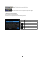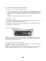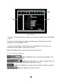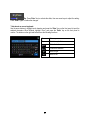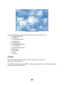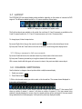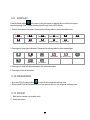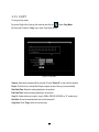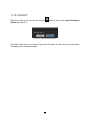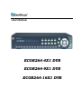
1
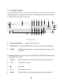
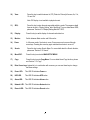
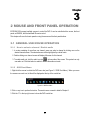
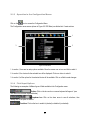
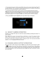
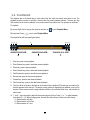
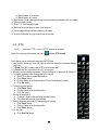
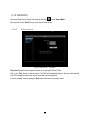
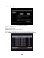
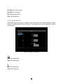
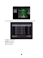
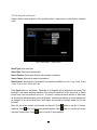
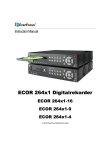
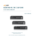
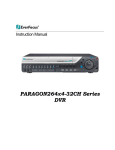
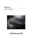
User Manual
ECOR264-4X1 DVR
ECOR264-9X1 DVR
ECOR264-16X1 DVR
1.4 FRONT PANEL
Your primary interaction with your new DVR will be through the Front Panel buttons and their
corresponding buttons on the included IR Remote Control. Take a moment to learn where the keys are as
the remainder of the manual will refer to them often.
6
3
1
7
8
9
16
18
19
20
21
22
17
4
2
10
11
12
13
14
15
23
Figure 1-1 Front Panel
1)
Remote Control Receiver:
Receiver for IR remote control.
2)
USB 2.0 (front) For connecting USB-Flash-Drive to copy/archive video or for firmware upgrades.
3)
DVD+RW:
DVD+RW burner for DVD model. (D models only) (Replaced by hot swap drive on
“R” models).
4) Channel keys 1~16 (1~9, 1~4): Press channel key (CH1~CH16) / (CH1~CH9) / (CH1~CH4) to display
that channel in full screen view.
5)
◄I /◄◄:
Fast reverse playback or step reverse playback depending on playback mode.
6)
I I / ◄:
Reverse playback or pause
7)
■
Stop playback
8)
►/ I I:
Forward playback or pause
9)
►►/I►:
Fast Forward playback or step forward playback depending on playback mode.
5
10)
View:
Press this key to switch between 4x, PiP (Picture In Picture),full screen, 9x, 10x,
13x and 16x.
Note: PIP display is not available in playback mode.
11)
SEQ:
Press this key to enter the auto sequential switching mode. The sequence dwell
time can be set in “Display Setting” tab of the Menu. For more detail about SEQ,
please see “Section 4.9.2 Display Setting-Main M/T SEQ”.
12)
Display:
Press this key to switch display of channels and status bar.
13)
Monitor:
Switch between Main monitor and Call monitor.
14)
Zoom:
In full screen mode, 2x electronic zoom. Zoom screen can be moved through
arrow keys. Pressing the zoom key again switches the electronic zoom off.
15)
Search:
16)
Menu/ESC:
Press this key to enter/exit MAIN SETUP MENU.
17)
Copy:
Press this key to enter Copy Menu. For more detail about Copy function, please
see “Section 3.13 Copy”.
18)
Enter/ Arrow keys: Instead of or in combination with a mouse, you can use these keys to change
the Menu settings.
19)
Power LED:
This LED ON indicates Power on.
20)
HDD LED:
This LED ON indicates HDD active.
21)
Alarm LED:
This LED ON indicates Alarm active.
22)
Network LED: This LED ON indicates Network active.
23)
Record LED: This LED ON indicates Record active.
Press this key to enter Search Menu. For more detail about the Search function,
please see “Section 3.12 Search”.
6
Chapter
3
2 MOUSE AND FRONT PANEL OPERATION
ECOR264 DVRs support multiple sources to control the DVR. It can be controlled with a mouse, the front
panel, an EKB500, and the handheld IR remote control.
This chapter will cover the basic operation using the mouse and the front panel buttons.
2.1 GENERAL USB MOUSE OPERATION
2.1.1
How to select a channel / Enable audio
1. In a view consisting of more than one channel, users can select a channel by clicking once on the
desired channel screen. The selected screen will be highlighted by a white frame.
2. Double clicking on a channel screen will display full screen for this channel.
3. To enable audio out, click the audio icon (ex:
) at lower side of the screen. This system has only
one audio out. Click this button to enable or disable the audio-out mode.
2.1.2
OSD Root Menu
1. Right-click the mouse to obtain the DVR menu bar (see Figure 2-1 OSD Root Menu ). When you move
the mouse over each icon, its title will be displayed at the top of the control bar.
Figure 2-1 OSD Root Menu
2. Click on any icon to perform that action. These actions are covered in detail in Chapter 3.
3. Click the “X” in the top-right corner to close the DVR control bar.
15
2.1.3
Operation in the Configuration Menus
Click on the
icon to access the Configuration Menu.
The Configuration menu screens (shown in Figure 2-2 OSD Menu) are divided into 3 main sections.
1
2
3
Figure 2-2 OSD Menu
1. In section 1, there are ten setup options available. Move the mouse over an icon and click to select it.
2. In section 2, the choices for the selected icon will be displayed. Click on a choice to select it.
3. In section 3, all the options for the selected choice will be available. Click on a field to make changes.
2.1.4
Field Input Options
The following are examples of different types of fields available in the Configuration menu.
Textbox: Click on the box and an on-screen keyboard will appear*. (see
note about the on-screen keyboard below)
Dropdown box: Click on the down arrow to see all selections, then
directly click on an option to select it.
Check box: Click on the box to enable it (checked) or disable it (unchecked).
16
Button: Click the button to execute the function.
Bar: Click and hold on the bar to adjust the set point Left or Right.
* Note about on-screen keyboard:
Click on a button to input that character.
The buttons on the right and bottom have the following functions:
Space
Enter a space
Caps
Switch to capital letters
Delete the letter
Confirm the selection
Move to right
Move to left
17
2.2 General Front Panel Operation
2.2.1 How to select a channel / Enable audio
1. In a view consisting of more than one channel, press the arrow keys (Up/Down/Right/Left) to scroll
through each channel that is displayed. The selected channel will be highlighted by white frame.
Pressing the “left” or “right” arrow when the last/first camera (1,4, 9 or 16) is highlighted will select all
cameras.
2.
While channel #1 is selected, press the “Enter” button to turn Audio On/ Off.
2.2.2 OSD Root Menu
1. Press “Menu” key to display the DVR menu bar. Use the left/right arrows to scroll over each icon. The
title for each icon will be displayed on top of the menu bar.
2. Press “Enter” key on any icon to perform that action. These actions are covered in detail in Chapter 3
3. Press “Menu” to close the DVR menu bar.
2.2.3 Front Panel Key Review
The basic principle of front panel operation is to use arrow keys to navigate among the menu items. Use
the “Enter” key to confirm a selection or enter the next level menu. Press the “Menu” key to enter the Main
Menu or exit from the current level of the menu.
2.2.4
Operation in Configuration Menu
Press “Menu”, use the arrow keys to highlight the “Configuration” icon, and press “Enter” with
“Configuration” icon highlighted to bring up the Configuration menu.
NOTE: If the require password option is active, you will need to log in first. Refer to “Section 3.2 LOGIN” for
information on logging in. The menu (shown in Figure 2-3 OSD Menu ) is divided into 3 main sections.
18
1
2
3
Figure 2-3 OSD Menu
1. In section 1, there are ten setup options available. Use arrow keys to highlight an icon and press “Enter”
to select it.
2. In section 2, the main choices for the selected icon will be displayed. Use Up/Down arrow keys to
highlight a choice and press “Enter” to select it.
3. In section 3, all the options for the selected choice will be available here. Use arrow keys to move
between items and press “Enter” to make changes to that item.
Note: press the “Menu” button to go back to the previous menu section/level.
2.2.5
Field Input Options
Textbox: Press Enter key and an on-screen keyboard will appear*. (see
note about on-screen keyboard below)
Dropdown box: Press “Enter” key to show the available options. Use
arrow keys to highlight the desired option and press “Enter” again to select it.
Check box: Press “Enter” key on a setting to enable it (checked) or disable it (unchecked).
Button: Press “Enter” key to execute the function.
19
Bar: Press “Enter” key to activate the slider, then use arrow keys to adjust the setting.
Press “Enter” again to finalize the changes.
* Note about on-screen keyboard:
Use the arrow buttons to highlight each character and press the “Enter” key on the front panel to input the
selected characters. When finished, highlight “Done” and press the “Enter” key on the front panel to
confirm. The buttons on the right and bottom have the following functions:
Space
Enter a space
Caps
Switch to capital letters
Delete the letter
Confirm the selection
Move to right
Move to left
20
Chapter
3
3. GENERAL DVR OPERATIONS
This chapter introduces the operations on major functions including playback, layout change, sequence,
triplex operations, copy, and search.
3.1 RECORD
By default, the DVR will always be in record mode. When the DVR is turned on, it will start to record. The
exceptions are:
1. DVR will not record any uninstalled cameras (Refer to Section 4.3.1 for more details)
2. If a schedule is active, the DVR will follow the record settings of the schedule.
3.2 LOGIN
In order to access ECOR264 options, users may be asked to log in for authority identification. To log in,
follow these steps.
1. Right click on the screen or press the Menu Key to display the Main Menu
2. Choose or click (or press “Enter” key) on the Configuration icon to bring up the following screen:
Figure 3-1 Login page
3. Select the user name from the drop-down list and input the password. The defaults are:
User name: admin (lower case)
Password: 11111111
21
+ To input password by mouse: click the password field to bring up the on-screen keyboard (see Figure 3-2
On-screen Keyboard). Click on each button to input the desired characters for the password. When finished,
click “Done” on the on-screen keyboard to confirm the password.
+ To input password using front panel: use the arrow keys to select the password field, then press the
“Enter” key to show the on-screen keyboard (see Figure 3-2 On-screen Keyboard). Use the arrow buttons
to highlight each character and press the “Enter” key on the front panel to input the selected characters.
When finished, highlight “Done” and press the “Enter” key on the front panel to confirm the password.
+ Click (or press “Enter” key when highlighted) on the “Login” button to log in to the system.
Figure 3-2 On-screen Keyboard
3.3 SELECT CAMERA OPERATION
ECOR264 is a pentaplex DVR; users can control each camera individually by selecting that camera. For
camera selection:
Mouse: Right-click the screen, the image will show a white frame on screen if the camera has been
selected. When in quad display mode, press the quad layout icon in layout menu to select all four cameras.
Front panel: Use the arrows to change the selection. Pressing the “right” or “left” arrow when the last/first
camera (1, 4, 9 or 16) is highlighted will select all cameras.
3.4 CHANGE AUDIO OUTPUT OPERATION
Use the arrow keys to select camera #1 and press “Enter” key to switch audio output on and off. An audio
icon will appear on the screen. Please make sure “Record Audio” option under Camera 1 Basic Settings
setup menu is ON if audio recording is required. Also, the audio source and/or audio output amplifier have
to be connected properly in order to utilize the audio functions. Note: Only Cam#1 controls audio, all others
do not control audio.
22
3.5 PLAYBACK
The playback bar is the fastest way to show video from the exact time which users want to see. The
playback bar allows a user to see both a time line and the current playback indicator. The user can then
click the time line to move the indicator to the position which they want to see. The operation is as follows:
To playback:
By mouse: Right-click to bring up the menu bar and click on
By front panel: Press
to enter Playback Menu.
key to enter Playback Menu.
The playback bar will show (see figure below):
1 2 3 4
9
5 6 7 8
2009/05/25 09:09:30PM
10 11 13
2009/05/25 09:09:40PM
14
15
12 10 10
2009/05/25 09:10:30PM
16
1. Stop key: press to stop playback
2. Slow Reverse key: press to start slow reverse playback
3. Pause key: press to pause playback
4. Slow Forward key: press to start slow forward playback
5. Fast Reverse key: press to start fast reverse playback
6. Reverse key: press to start reverse playback
7. Forward key: press to start forward playback
8. Fast Forward key: press to start fast forward playback
9. Time bar: Move the slider on the time bar to the select time to playback (The start time and end time for
time bar appears below the bar). The status of each camera is represented by different colors on the
time bar. Green means normal; orange indicates a Motion; blue indicates Video Loss, red indicates an
alarm event.
10. “+” and “-“ signs are used to adjust the time scale range for the bar. Press “+” or “-“ to select between
scale levels L1 ~ L5. When changing level, the start time and end time of the time bar will change
L1: Entire time bar is 2 days
L2: Entire time bar is 30 hours.
L3: Entire time bar is 1 hour.
23
L4: Entire time bar is 10 minutes.
L5: Entire time bar is 1 minute.
11. Express copy: Press to start express copy when camera during playback (only one camera)
12. Playback speed indicator
13. Press “X” to close the playback bar.
14. Start time for bar (the left-most point of the time bar)
15. Current playback time (the time indicated by the slider)
16. End time for time bar (the right-most point of the time bar)
3.6 PTZ
3.6.1
General PTZ control (if PTZ cameras are installed)
Right-click to bring up the menu bar and click on
to display PTZ Controls.
The following actions can be performed using the PTZ Menu:
1. Use Direction Arrows (up, down, left, right) to move the camera to the desired direction
and angle.
2. To Zoom, Click “Z+” to zoom closer or “Z-” to zoom farther away.
3. To Focus, click “F+” to focus far or click “F-” to focus near.
4. With Iris, you can increase the amount of light by clicking “I+” or decrease it by clicking “I-“.
5. To program a preset position (if supported by the camera)
a. Move PTZ camera to the specified position
b. Click “Preset” button
c. Click the number of the desired position (This will be displayed in the box)
d. Click “Set” button
6. To jump to a preset position
a. Click “Preset” button
b. Click the number of the desired position
c. Click “Go” button
7. Shortcut for presets #1-9
a. Click digit 1-9 button without clicking any other buttons
b. The camera will seek that preset position
8. Steps to delete a preset position (if supported by the camera)
a. Click “Preset” button
b. Click the number of the desired position
c. Click “Delete” button
9. For Auto Pan
a. Click “Auto Pan” button
24
10. Pattern Operation (Pattern is the “0” Tour in Everfocus and Pelco PTZ cameras)
a. Click “Pattern” button
11. Steps to run a tour
a. Click “Tour” button
b. Click the number of the desired tour
c. Click “Go” button
12. Steps to remove a tour (if supported by the camera)
a. Click “Tour” button
b. Click the number of the desired tour
c. Click “Delete” button
Click “C” to clear the digit in the number display
Click “X” at the top-right corner to hide the PTZ menu (see Express control below)
Click “Exit” to leave PTZ function.
REMEMBER:
Click “X” at the top-right corner to hide the PTZ menu (see Express control below)
Click “Exit” to leave PTZ function.
“X” only HIDES the PTZ control panel. “EXIT” closes the panel and exits PTZ mode!! Other controls will not
respond until you EXIT the PTZ mode!!
3.6.2
Express Control of PTZ
If the PTZ control panel/menu has first been opened and then hidden, the mouse can be used to control
basic PTZ functions (Quick Mouse Control). The mouse cursor will change to different icons in different
areas of the screen. With Quick Mouse Control, the user can control PTZ direction, zoom, and focus by
clicking directly on screen. The screen is divided into 16 areas, with the outer ring is divided into 12 zones
used to control movement direction. The inner square of 4 areas is used to control zoom and focus.
25
Figure 3-3 Express Control PTZ
The screen is divided into a 4x4 grid. The function of each section is defined as below:
• 1: PTZ pan/tilt left and up
• 2, 3: PTZ tilt up
• 4: PTZ pan/tilt right and up
• 5, 9: PTZ pan left
• 8,12: PTZ pan right
• 13: PTZ pan/tilt left and down
• 14, 15: PTZ tilt down
• 16: PTZ pan/tilt right and down
• 6: Focus closer
• 10: Focus further
• 7: Zoom in
• 11: Zoom out
REMEMBER:
Click “X” at the top-right corner to hide the PTZ menu (see Express control below)
Click “Exit” to leave PTZ function.
“X” only HIDES the PTZ control panel. “EXIT “ closes the panel and exits PTZ mode!! Other controls will not
respond until you EXIT the PTZ mode!!
26
3.7 LAYOUT
The ECOR264 DVR has several display modes available, depending on the number of cameras the DVR
supports. The different available layouts for a 16 camera model are shown below:
NOTE: PIP display is not available in Playback mode
The first three layouts are available on all models; the next three (6, 8 and 9 cameras) are available on the
9 and 16 camera models; the 10, 13 and 16 camera screens only on the 16 camera model.
To change layout, follow the steps below:
By mouse: Right-click to bring up the menu bar and click
then click on the desired layout choice.
By front panel: Push the “View” button on the front of the DVR to scroll through each display format.
3.7.1 Bring a camera to full screen mode
By mouse: Double left-click on the selected channel to put that camera in full screen mode.
By front panel: Press any channel key to bring that channel to full screen mode.
With a mouse, double left-click again on the screen to return to the previous multiple camera layout.
3.8 CHANNEL SWITCHING
Use this function to change a channel position within a multiple camera display
1. Select one camera
2. Press Channel button
.
3. Click on the channel number you wish to select on the channel bar. The camera channel displayed in
that position will be switched.
EX: On a four camera screen, select camera1 and enter Channel menu and choose “2”, then camera 2 will
show on position of camera 1, camera 1 will show on position of camera 2. If the new camera being
selected is already displayed on screen, then the camera positions will be exchanged. If the new camera
being selected does not already appear, it will replace the previously displayed camera.
27
3.9 DISPLAY
Press the Display button
on the menu by using the mouse or selecting this icon with the front panel
keys and pressing ‘Enter’. Pressing/clicking cycles through the four OSD formats:
1. Press to show camera information. Please see the following table for camera information icons.
Recording
Playback
Fast forward
Fast backward
Back
Alarm
Motion
Video loss
Express copy
Audio out
pause
3. Press again to show status information. Please see the following table for status representation.
Alarm
Audio
Event
HDD failure
Motion
Video loss
No network
HD temp. too high
Seq.
4. Press again to show both status information and camera information.
5. Press again to hide all information.
3.10 SEQUENCE
1. By mouse: Click Sequence button
to enter the auto sequential switching mode.
2. By front panel: Press the Sequence button on front panel to enter the auto sequential switching mode.
3.11 ZOOM
1. Make sure no camera is in playback mode
2. Select one camera
28
3. Right-click to bring up the menu bar and click
panel.
button. Or, press the ZOOM button on the front
4. When in ZOOM mode, the mouse cursor will change to a different icon in different areas of the screen.
Or, use the arrow keys to bring a different portion of the magnified image into view. Users can control
the portion of the magnified image to be displayed by clicking directly on screen:
Figure 3-4 Zoom Express Control
The screen is divided into a 4x4 grid. The function of each section is defined as below:
• 1: Left and up
• 2, 3: Up
• 4: Right and up
• 5, 9: Left
• 8,12: Right
• 13: Left and down
• 14, 15: Down
• 16: Right and down
• 6, 7, 10, 11: Not used
29
3.12 SEARCH
By mouse: Right-click to bring up the menu bar and click
to enter Search Menu.
By front panel: Press ”Search” key to enter Search Menu directly.
3.12.1
Time Search
Figure 3-5 Search Menu – Time Search
Play From: Select the time to begin the search by choosing the Date and Time.
Click on the “Play” button to start the search. The DVR will automatically begin to play the video selected.
The DVR will play the nearest time if there is no data at the selected time.
In search playback mode, pressing the “Stop” button will return to the search menu.
30
3.12.2
Event Search
Figure 3-6 Search Menu – Event Search
From: Select starting date and time
To: Select ending date and time.
Camera: Select which cameras to include in the search.
Event: Select which event type(s) to search for. Choose from Alarm, Motion or Video Loss.
Click on the “Search” button to start searching. The search results will be shown as a list of events.
31
Prev Page: Go to previous page
Next Page: Go to next page
Play: Playback selected item
Copy: Copy selected item
3.12.3 Smart Search
Smart Search allows the review of a segment of the recorded video from individual cameras to detect
motion in an area specified at the time of the search. The resulting ‘motion events’ are displayed in the form
of an Event List.
Figure 3-7 Search Menu – Smart Search
From
Date: Select starting date.
Time: Select starting time.
To
Date: Select ending date.
Time: Select ending time.
32
Camera: Select which cameras to review.
Grid Setting: Press Grid Setting button to open the motion grid setup window.
Edit Motion Grid: Press this button to edit the motion grid (See Figure 4-5 Camera Menu – Motion Grid
Setting ).
Set All: Press this button to select the entire area.
Clear All: Press this button to clear all the grids selected.
Save & Back: Press this button to save the motion grid setting and return to motion setting menu.
Cancel: Press this button to cancel all changes and returns to the motion setting menu.
How to select motion grid by mouse:
1. Click on the image and the grid will display.
2. Select the grid square in the upper-left of the desired rectangle.
3. Select the grid square in the lower-right of the desired rectangle.
4. The area between upper-left and lower-right grid will be selected.
The same result is achieved from lower left followed by upper right.
5. Choose “Save & Back” to proceed.
How to select motion grid by front panel:
1. Press Enter key on “Grid Setting” to launch motion grid setting page. .
2. Use arrow keys to scroll above or below list of buttons to enter the grid setting area.
3. Press Enter key to display grid.
4. Use arrow keys to choose one corner of desired area
5. Press Enter key at the starting point.
6. Use arrow keys to select motion area; the shape of the proposed area will be displayed.
Press Enter key at the end point, and the area will be selected.
Press the Menu key to exit the area selection; use the up/down arrows to choose “Save & Back” and press
Enter to proceed.
33
Click on the “Search” button to start searching. The search results will be shown as a list of events.
Prev Page: Go to previous page
Next Page: Go to next page
Play: Playback selected item
Copy: Copy selected item
34
3.12.4 Snapshot Search
Snapshot Search shows snapshots of the specified interval, it helps users to quickly find the interested
scene.
Figure 3-8 Search Menu – Snapshot Search
Result Type: Select result type.
Search Date: Select search date and time
Search Direction: Select search direction, either forward or backward.
Search Camera: Select which camera to be searched.
Result Interval: Select interval of the snapshot to be searched. Available from 1 min, 5 min, 10 min, 30 min,
1 hour, 2 hour, 4 hour, 12 hour and 1 day.
Press Search button to start Search. Thumbnails of the Snapshot will be displayed on the screen. First
thumbnail is the search date/time, date/time of the second thumbnail will be the interval set in “Result
Interval” next to the first thumbnail, and so on. If “forward” is selected as search direction, a white frame
will surround the selected snapshot at the first thumbnail. If backward is selected, the search date/time will
be displayed at the last thumbnail and a white frame will surround the selected snapshot at the last
thumbnail.
Right click the mouse to obtain a hint window, see figure 3.9. Press
button to view the 16 previous
snapshots. Press
button to close the hint window
button to playback the selected snapshot. Press
and return to search menu. Press
button to view the 16 next snapshots.
35
Figure 3-8 Search Menu – Snapshot Search result
36
3.13 COPY
To bring up Copy menu:
By mouse: Right-click to bring up the menu bar and click on
to enter Copy Menu.
By front panel: Press the “Copy” key to enter Copy Menu directly.
Figure 3-10 Copy Menu
Camera: Select which cameras will be archived. Choose “Select All” to select all the cameras.
Player: Check the box to include the ePlayer program as part of the copy (recommended).
Start Date/Time: Select the starting date/time to be archived.
End Date/Time: Select the ending date/time to be archived.
Copy To: Select whether you want to copy to USB or CD DVD (CD/DVD on “D” models only).
Data Size: Shows the estimated total size for the time period.
Copy Now: Press “Copy” button to start archiving.
37
3.14 LOGOUT
Right-click to bring up the menu bar and click the
window (see Figure 3-11).
button to bring up the Logout Confirmation
Figure 3-11 Logout Confirmation window
Press “Yes” button when you are ready to logout from the system. You will need to login again before
accessing any other configuration options.
38