1
TK14 THERMAL PRINTER
Operation manual - Version 1
February-2006
FENIX IMVICO
TK14 OPERATION MANUAL
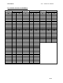
TK14 thermal printer operation manual revision:
Page
Revision type
Before change
Version 1 Date: Febraury 2006
After change
2/65
FENIX IMVICO
TK14 OPERATION MANUAL
INDEX
IMPORTANT NOTES IN TK14 THERMAL PRINTER MANAGEMENT................6
0 – INTRODUCTION............................................................................................ 8
1 – GENERAL SPECIFICATIONS....................................................................... 9
1.1- Printing specifications................................................................................................. 9
1.2- Character specifications.............................................................................................. 9
1.3- Passive cutter.............................................................................................................. 10
1.4- Paper specifications.................................................................................................... 10
1.5- Internal buffer.............................................................................................................. 10
1.6- Electrical specifications.............................................................................................. 10
1.7- Environmental conditions........................................................................................... 10
2 – INSTALLATION.............................................................................................. 11
2.1- TK14 ISNTALLATION CONSIDERATIONS............................................................... 11
2.2- POWER SUPPLY........................................................................................................ 13
2.3- RS-232 SERIAL INTERFACE..................................................................................... 14
2.3.1- RS-232 Serial interface specifications......................................................... 14
2.3.2- Change between online and offline mode................................................... 14
2.3.3- Serial RS-232 interface pins assignment..................................................... 15
2.3.5- PC serial interface connection .................................................................... 15
2.4- CENTRONICS PARALLEL INTERFACE.................................................................... 16
2.4.1- Compatibility mode...................................................................................... 16
2.4.2- Reverse mode............................................................................................. 17
2.4.3- Parallel interface pins assignment for each mode....................................... 17
2.4.4- PC parallel interface connection ................................................................. 18
3 – BASIC OPERATIONS.................................................................................... 19
3.1- PAPER LOADING....................................................................................................... 19
3.1.1- Automatic paper load................................................................................... 19
3.1.2- Manual paper load....................................................................................... 19
3.2- BUTTONS FUNCTIONS............................................................................................. 20
3.3- PAPER SENSORS..................................................................................................... 20
3.4- OPEN PLATEN SENSOR.......................................................................................... 21
3.5- LED INDICATOR........................................................................................................ 21
3.6- SPECIAL PRINTING MODES.................................................................................... 21
3.6.1- Self-test mode............................................................................................. 21
3.6.2- Programming mode......................................................................................22
3.6.3- Hexadecimal dump mode........................................................................... 23
3.7- ERROR PROCESSING.............................................................................................. 24
3.7.1- Error types................................................................................................... 24
3.7.2- Printer operation when an error happens.................................................... 27
3.7.3- Data reception error (serial interface only).................................................. 27
3.7.4- Flow diagram of the error detection for the serial port................................ 27
3.7.5- Flow diagram of the error detection for the parallel port............................. 28
4 – CONTROL COMMANDS................................................................................ 29
4.1- COMMAND NOTATION.............................................................................................. 29
4.2- TERM DEFINITIONS.................................................................................................. 29
4.3- DESCRIPTION OF THE CONTROL COMMANDS.................................................... 30
3/65
FENIX IMVICO
TK14 OPERATION MANUAL
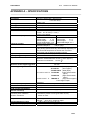
APPENDIX A – SPECIFICATIONS...................................................................... 45
APPENDIX B – IF1500 CONNECTORS AND BUTTONS................................... 46
APPENDIX C – EXTERNAL APPEARANCE........................................................ 47
APPENDIX D – HOW TO ORDER ...................................................................... 48
APPENDIX E – CODE128 BAR CODE................................................................ 49
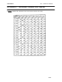
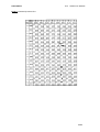
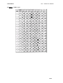
APPENDIX F – INTERNAL CHARACTER TABLES............................................. 53
APPENDIX G – TESTING SOFTWARE............................................................... 56
4/65
FENIX IMVICO
TK14 OPERATION MANUAL
FIGURES AND TABLES
Fig. a. Thermal print head cleaning................................................................................................. 7
Fig. 2.1- TK14 accessibility............................................................................................................. 11
Fig. 2.2- Nozzle hole dimension...................................................................................................... 12
Fig. 2.3- TK14 earth connection.................................................................................................... 12
Fig. 2.4- TK14 power supply connector………………...........….....…............…………………........ 13
Fig. 2.5- Current consumption example……......……………………………………………............... 13
Fig. 2.6- Serial RS-232 interface pins...........………………………………………………….............. 15
Fig. 2.7- PC serial cable................................................................................................................. 15
Fig. 2.8- Parallel interface pins....................................................................................................... 18
Fig. 2.9- PC parallel cable............................................................................................................... 18
Fig. 3.1- Automatic paper load………………………………………………………........................... 19
Fig. 3.2- Platen opened.................………………………………………………................................. 19
Fig. 3.3- TK14 led and buttons........................................................................................................ 20
Fig. 3.4- Near-end paper sensor localization.....……………………………………………................ 20
Fig. 3.5- SELF-TEST mode example.............................................................................................. 21
Fig. 3.6- PROGRAMING mode example......................................................................................... 22
Fig. 3.7- HEXADECIMAL dump mode example…………………………………………….................23
Fig. 3.8- LED blinking sequence (RED)…..............………………………………………………........ 24
Fig. 3.9- Paper jam recovery........................................................................................................... 26
Fig.3.10- Serial port error flow diagram....................................... ………………………………........ 27
Fig.3.11- Nibble mode phase transitions .......……………………………………………………......... 28
Table 2.1- RS232 Serial connector pin assignments .......………………………………….............. 15
Table 2.3- PC parallel connector .......................…….........…………………………………............. 17
Table 4.1- List of commands.......................................................................................................... 30
5/65
FENIX IMVICO
TK14 OPERATION MANUAL
IMPORTANT NOTES IN TK14 THERMAL PRINTER MANAGEMENT
In order to preserve the life of the printer, it is necessary to keep in mind some precautions in the handling
of the TK14 printer. Please read carefully the following points in order to make a good use of the printer.
SECURITY PRECAUTONS
• Before using the printer, read carefully section 2-INSTALLATION.
• NEVER connect the external power supply with the wrong polarity. This could permanently damage the
printer.
• Turn off the printer immediately if it produces smoke, a strange smell or an unusual noise. Keeping on
using the printer could cause fire. Unplug the equipment immediately and contact your official
distributor.
• NEVER connect cables with different connectors from the ones mentioned in this manual. Making
different connections could permanently damage the printer.
• Use a power supply voltage whose output voltage is within the specification range stated in this
manual. Over voltage can permanently damage the printer. Under voltage can cause malfunctions.
• NEVER wet TK14 thermal printer with water or any other liquid. If any liquid is spilled inside of the
equipment, unplug the power cable immediately and then contact your technical service.
• Make sure the printer is on a steady, horizontal, securely fixed surface. If the printer fell down, it could
break or damage.
• NEVER use the printer in high humidity or dirty places.
• NEVER place heavy objects on top of the printer and never lean on it.
• NEVER put any object inside of the printer, as it could cause hardware damage on it, such as shortcircuit, print head breaking or general failure of the printer.
• NEVER shock the TK14 printer.
• NEVER disassemble or modify the TK14 printer.
• NEVER try to repair the TK14 printer. Please contact your official distributor in case of failure.
• As the printer contains electromagnets (inside of the motor), it should not be used in excessively dirty
environments or places with dust or metal particles.
• NEVER print without paper loaded or without the cover closed, as the thermal print head life can be
highly shortened.
• NEVER pull the paper out when the cover is closed. Use the paper advance button instead.
• Avoid touching with metal objects, such as screwdrivers or tweezers, the print head thermal elements
as well as the electronic printed circuit. They are delicate parts.
• Never touch with your hands the areas around the print head and the motor surface as they become
very hot during and just after printing; wait 15 seconds to let them cool down.
• NEVER touch the surfaces of the print head thermal elements or the electronic printed circuit, as dust
and dirt can stick to their surface and cause damage by electrostatic discharge.
• The thermal paper contains Na+, K+ and Cl- ions that can cause harm to the print head elements.
Therefore, use only the specified paper.
• If the printer has not been used for long period of time and the paper was loaded, the paper could
become deformed by the drive roller pressure. It is recommended to make it advance at least 30 mm
before printing again.
• For security reasons, unplug the printer if it is not going to be used over a long period of time.
• Don’ t print continuously (without stopping) for more than 6 minutes.
6/65
FENIX IMVICO
TK14 OPERATION MANUAL
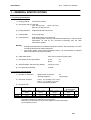
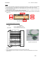
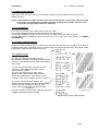
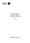
• CLEANING PROCEDURE AND PRECAUTIONS
In order to clean the thermal print head, proceed as indicated by the following steps:
1. Unplug the power supply cable and remove the 4 screws (2 in each side) holding the thermal print
mechanism. Open the printer cover. Wet a cotton sponge in alcohol (ethanol, methanol or IPA),
and use it in order to clean the thermal elements of the print head and to remove the possible
accumulation of paper particles found on the cover, roller and nearby surfaces.
2. Wait for alcohol to evaporate before inserting the paper roll and closing the cover.
FENIX recommends cleaning the thermal print head periodically (each 2 or 3 months) in order to keep
the print quality.
NOTES:
! The print head could be hot after printing. Make sure it has thoroughly cooled down
before proceeding to clean it.
! Never touch the thermal elements of the print head with your hands.
! Never use metallic or piercing elements for the cleaning of the print head, as they
could scratch it.
Thermal
head
Screws
Fig. a. Thermal print head cleaning.
RECOMMENDATIONS
•
•
•
The plug has to be located near the printer and have to be easily obtainable.
Before connecting any communication data cable, check the printer is working properly by executing
the self-test.
Set the TK14 in a place where the connection cables do not suffer stretching or cross with each other.
7/65
FENIX IMVICO
TK14 OPERATION MANUAL
0 – INTRODUCTION
The TK14 is a high performance thermal printer. Its compact and functional design covers many
professional uses (as in supermarkets, hotels, hospitals, restaurants, and so on.)
It is capable of printing text, graphics, logo and barcodes.
It can be used in laboratories, industrial and professional environments.
The main features of the TK14 are:
•
•
•
•
•
•
•
•
•
•
•
•
•
•
•
•
•
•
•
•
•
•
•
•
•
•
Simple installation and easy maintenance.
Low noise thermal printing.
Full-logic ticket presentation through intelligent processor, controlling even printer status.
Paper width: 58 mm.
High reliability: 100 million pulses. Abrasion resistance: 50 Km.
Power supply: 12V to 24V DC.
No-paper, paper-near-end and paper jam sensors.
Up to 80 mm paper roll diameter.
High speed printing up to 62,5mm/s.
Printing resolution: 8 dots/mm (203 dpi).
Passive cut of paper.
Nozzle ticket presenter.
IEEE 1284 parallel and serial RS232C data input interface on-board.
Two internal character fonts (A font = 12x24 dots. B font = 8x16 dots).
Scalable font (independent scale in X/Y-axis), up to 64 times.
Programmable character and line space.
Bold and reverse character capabilities
Graphic bitmap printing capabilities.
Several format Bar Code (EAN13, Code39, Code128 and ITF)
Control code based on ESC/POS commands (*).
Hexadecimal mode for easy software debugging.
Automatic paper load.
Extended operating temperatures range (-30ºC to +70ºC).
Self test, hexadecimal mode and configuration mode features.
One logo load capability, through Windows driver.
Windows 95, 98 & 2000 drivers and demo/configuration program.
This manual is the printer operations’ guide and is intended for the application designer. The following
sections contain a detailed description of both the hardware and the configuration software that allow
obtaining the maximum benefit of the printer possibilities.
(*) ESC/POS are registered trademarks of Seiko Epson Corporation.
8/65
FENIX IMVICO
TK14 OPERATION MANUAL
1 – GENERAL SPECIFICATIONS
1.1- Printing specifications
1) Printing method:
Thermal line printing
2) Dot density:203 dpi x 203 dpi
(‘dpi’: dots per inch. 1 inch = 25.4mm)
(203 dpi = 8 dots per mm)
3) Printing direction:
Unidirectional with friction feed.
4) Printing width:
48 mm (384 dots).
5) Printing speed:
High speed mode: up to 62,5mm/s
(The printing speed could vary automatically depending on the print head
temperature as well as the command processing and the data
transmission speed).
NOTES:
"
"
Printing speed depends on the data transmission interface, the combination of control
commands and the print head temperature.
Low printing speed could cause intermittent printing. It is recommended to transmit
data to the printer as quickly as possible.
6) Paper feed speed:
62,5 mm/s (continuous paper feed)
7) Characters per line (by default):
A font:
B font:
8) Space between characters (by default):
4 dots (0.5 mm)
9) Line spacing (by default):
3.75mm
24
32
1.2- Character specifications
1) Number of characters:
Alphanumeric characters:
Extended graphics:
95
128 per page
2) Character structure:
A font: 12 x 24 dots (1.5 x 3 mm).
B font: 8 x 16 dots (1 x 2 mm).
A font is selected by default.
3) Character size:
Standard
A Font
B Font
Double height
Double width
Double width/
Double height
Width x height cpl Width x height cpl Width x height cpl Width x height cpl
(mm)
(mm)
(mm)
(mm)
1,5 x 3
24
1,5 x 6
24
3x3
12
3x6
12
1x2
32
1x4
32
2x2
16
2x4
16
The space between the characters is not included.
Characters can be scaled up to 64 times bigger than their normal size.
cpl: characters per line.
9/65
FENIX IMVICO
TK14 OPERATION MANUAL
1.3- Passive cutter
The TK14 has a passive cutter system. After present the ticket printed in the nozzle, user can take it and,
himself, cuts the paper, without any TK14 automatic action.
1.4- Paper specifications
1) Paper type:
2) Paper width:
3) Paper roll size:
4) Specified thermal paper:
At –5ºC to 50ºC #
thermal paper roll
58 +0/-1mm
up to a maximum of 80 mm of diameter (25 mm inner diameter)
TF50KS-E2D
TF77KS-E2
TL69KS-HG76
At –30ºC to 70ºC# TL51KS-R2
TL69KS-R2
At 5ºC to 40ºC # TW80KK-S
(59µm paper )
(95µm paper)
(label paper)
(High heat-resistant paper)
(High heat-resistant paper)
(2-ply thermal paper)
From Nippon Paper Industries
1.5- Internal buffer
The TK14 printer contains a 10 Kbytes internal memory, whose functionality is dynamically shared by the
receiving buffer.
This big receiving buffer allows the printer working in the following way: Firstly, all data are buffered, and
afterwards the printing is done at the maximum possible speed, without it being affected by the
communications time processing.
1.6- Electrical specifications
1) Power supply voltage:
12V to 24V DC ± 10%
2) Peak current consumption (ambient temperature, 64dots activated): 3A (approx.)
1.7- Environmental conditions
1) Temperature range:
Working temperature range: -30ºC to 70ºC
Storage temperature range: -30 a 60ºC (without paper loaded, in
a dry place).
10/65
FENIX IMVICO
TK14 OPERATION MANUAL
2 – INSTALLATION
2.1- TK14 INSTALLATION CONSIDERATIONS
There are some general considerations to take into account when installing the TK14 printer.
A wrong installation can cause many serious problems like paper jam, difficult maintenance of the printer,
difficulty in changing the paper roll, etc.
Moreover, a correct installation can prevent the printer from being damaged by external agents, such as
weather or vandalism.
This printer is thought to be fixed in a bigger case or structure, or another kind of appropriate chassis.
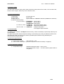
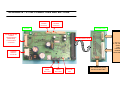
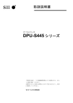
The basic points that a correct installation must follow are:
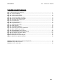
• Allow enough space and
accessibility to reach the
maintenance procedure points
Power supply and
in case it is needed.
comunication
Take notice that all user
connectors
accessible parts are in the
left and rear side of the
printer, like the next picture shows:
Led and buttons
Platen lever
Paper roll
Printed ticket
Fig. 2.1- TK14 accessibility.
•
Smooth exit of the ticket.
Prevent problems with static electricity due to the
nature of the used materials. Be sure to make a
good earth connection.
11/65
FENIX IMVICO
TK14 OPERATION MANUAL
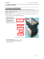
For these reasons, FENIX suggests the following systems as solutions to a correct installation:
The printer must be set quite near the front side of the user’s chassis.
Special care in the design of the part which goes from the printer outlet to the paper guide (paper jams
can occur due to an inappropriate design).
As the printer is placed very near the user’s chassis, some system must be implemented in order to move
the printer when accessing the printing head (i.e. giving the fixing holes of the chassis an oval shape to
allow the printer moving forward and backward).
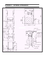
MINIMAL NOZZLE
HOLE DIMENSION IN
THE USER FRONT
PANEL
Fig. 2.2- Nozzle hole dimension.
Depending on the construction materials, care must be taken with static electricity; otherwise tickets may
get stuck in the paper guide and never reach the receptacle.
Be sure to make a good earth connection, performing one of the following schemes:
a) The earth connection is at
the power supply and shorted
with the negative terminal.
The chassis is connected to
earth shorting the jumper J1.
Tk14
Power
supply
C0N1
shorted
J1
Chassis
earth
Tk14
Power
supply
C0N1
NOT shorted
J1
Chassis
b)The negative terminal is
floating.
The chassis is connected to
earth by a cable from the
main earth connection.
M3 Screw + Grower
Fig. 2.3- TK14 earth connection.
12/65
FENIX IMVICO
TK14 OPERATION MANUAL
+12V to +24V
2.2- POWER SUPPLY
The TK14 is powered by an external power supply
by means of a female polarized connector of 4 pins
that includes a security anchor. The power supply
voltage must be verified before making the connection
between the supply and the printer.
The power supply male connector must be a
JST VH396-04-H (housing)
VH396T-010 (contact), or an equivalent model.
GND
Fig. 2.4- TK14 power supply connector.
NOTES:
(1) If the number of dots that are energized at the same time is increased, a higher current will flow;
therefore, the user should use a power supply with an adequate current capacity.
(2) When designing lines and bit images, take the printing ratio and print duty into consideration.
(3) Print quality may be poor if the printing ratio (energizing pulses/dot line) or print duty is high.
(3) Average energizing pulse width is defined as 64 of 192 dots/dot line that are energized.
WARNING: Beware not to invert the polarity of power supply. This may irremediably
damage the printer. Use the 4 terminals (4 wires) with 1 mm² minimum section everyone.
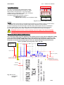
IMPORTANT NOTE ABOUT POWER SUPPLY:
The necessary supply of power depends on the content to print on the ticket. A 60W power supply
covers all adverse possibility (printing ratio of 100% black at any temperature). However, if the
print ratio is not over 60%, a 40W power supply can be used. Any way, power supply must meet
the peaks current that mechanism requires, which are determined by the following formula:
Ipeak = [(number of printing dots) x 8,3] / 176 [A]
Rshunt=0,02 Ω
Vi=12V
Input current
Ipeak = 5,1A
(5ms)
Ipeak = 3,9A
Ipeak= 2,2A
Istandby = 0,38A
( 40ms)
I(motor) = 0,5 A
(feed paper without printing)
1 dot line
2 dot lines
Fig. 2.5- Current
consumption
example.
13/65
FENIX IMVICO
TK14 OPERATION MANUAL
2.3- RS-232 SERIAL INTERFACE
2.3.1- RS-232 Serial interface specifications
•
•
•
•
Data transmission type:
Synchronization:
Flow control:
Signal levels (RS232):
•
•
•
•
•
Speed:
Data length:
Parity:
Stop bits:
Connector (user side):
Serial
Asynchronous
DTR/DSR control
MARK = -3 to -15 V
Logic ‘1’/OFF
SPACE = +3 to +15 V Logic ‘0’/ON
4800, 9600, 19200, 38400 bps (bps: bits per second)
8 bits
none, even, odd
Fixed to 1
JST PHDR-18VS (housing)
SPHD-001T-P0.5 (contact) or an equivalent model.
NOTE:
(1) Speed and parity depend on the settings (refer to section 3.6.2).
2.3.2- Change between online and offline mode
The printer is in offline mode:
1)
2)
3)
4)
5)
6)
When powering up or resetting the printer, until the printer is ready to receive data.
When the platen is opened.
After pressing the Paper feed button (FEED) while the paper advances.
When ‘out of paper’ causes the printer to stop printing.
When the power supply has a temporal abnormal voltage change.
When an error has occurred.
14/65
FENIX IMVICO
TK14 OPERATION MANUAL
2.3.3- Serial RS-232 interface pins assignment
The assignments of the terminals of the RS-232 connector and the functions of its signals are described in
the following table:
Pin
Signal
Signal
name direction (from
Function
the printer
point of view)
20
21
22
TXD
RXD
RTS
Output
Input
Output
24
23
Other
SG
DTR
nc
Output
---
Data transmission line.
Data reception line.
This signal indicates whether the printer is busy. SPACE
indicates that the printer is ready to receive data, and
MARK indicates that the printer is busy.
Signal ground.
This signal indicates whether an error occurs.
Not connected
Table 2.1- Pins Assignments of RS-232 connector terminals.
(*1) Definition of ‘data receiving buffer full’: the state of the printer becomes ‘buffer full’ when the receiving
buffer increases to 10 Kbytes maximum.
Note: The printer ignores the received data when the free space in the receiving buffer is 0 bytes.
Pin #19
Pin #21
Pin #23
Pin #24
Pin #20
Pin #22
Fig. 2.6- Serial RS-232 interface pins.
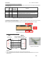
2.3.5- PC serial interface connection
PC
FEMALE DB9
TK14
Housing: PHDR-24VS (JST)
Contact: SPHD-001T-P0.5 (JST)
RXD 2
20
TXD
TXD 3
21
RXD
GND 5
23/24 GND
DSR 6
19
DTR
CTS 8
22
RTS
Fig. 2.7- PC serial cable.
shield to chassis
NOTES:
•
•
Same configuration in the printer and in the host system should be set.
The communication protocol should be set properly so that the transmitted data can be received
without errors.
15/65
FENIX IMVICO
TK14 OPERATION MANUAL
2.4- CENTRONICS PARALLEL INTERFACE
The TK14 comply the IEE1284 protocol (NIBBLE MODE).
Copyright © 1994 by the Institute of Electrical and Electronic Engineers, Inc.
2.4.1- Compatibility mode (Data transmission from host system to the printer: Centronics
compatible)
*Any system sending data to the printer (PC, PLC, custom board, et cetera) is considered to be a host
system.
The compatibility mode supports compatibility with the Centronics parallel interface.
a) Specifications
Data transmission:
8-bit parallel
Synchronization:
nSTB signal externally provided
Protocol:
nACK (acknowledge) and BUSY signals
Signal levels:
TTL compatible
Connector (user side):
JST PHDR-18VS (housing)
SPHD-001T-P0.5 (contact) or an equivalent model.
b) Switching between online and offline mode
The printer does not provide any switch for online/offline mode. The printer is in offline mode in the
following cases:
1) When powering on or until the printer becomes ready for data transmission after it is initialized by
the reset signal from the interface
2) During the self-test.
3) When the platen is opened.
4) During paper advance using the paper advance button (paper feed).
5) When the printer stops printing due to ‘out of paper’.
6) When a temporal voltage abnormality happens to the power supply.
7) When an error occurs.
c) Timing diagram of data reception
Data n
Data n+1
Data
tHold
nStrobe
tSetup
tSTB
Busy
Peripheral Busy
TReady
tBUSY
nAck
tnBUSY
tReply
tACK
tNext
16/65
FENIX IMVICO
TK14 OPERATION MANUAL
Specification
Description
Symbol
Data hold time
tHold
750
--
Data setup time
tSetup
750
--
STROBE pulse width
tSTB
750
--
READY cycle idle time
tReady
0
--
BUSY output delay time
tBUSY
0
500
Data processing time
tReply
0
∞
ACKNLG pulse width
tACK
500
10µs
BUSY release time
tnBUSY
0
∞
ACK cycle idle time
tNext
0
--
Min(ns) Max(ns)
2.4.2- Reverse mode (Data transmission from the printer to the host system)
The transmission of the printer status to the host system is implemented according to the IEEE1284
standard (NIBBLE MODE).
2.4.3- Parallel interface pins assignment for each mode
Pin
Source
Compatibility mode
Nibble mode
1
Host Sys.
nStrobe
HostClk
2
Host Sys/printer
Data0 (LSB)
Data0 (LSB)
3
Host Sys/printer
Data1
Data1
4
Host Sys/printer
Data2
Data2
5
Host Sys/printer
Data3
Data3
6
Host Sys/printer
Data4
Data4
7
Host Sys/printer
Data5
Data5
8
Host Sys/printer
Data6
Data6
9
Printer
Data7 (MSB)
Data7 (MSB)
10
Printer
nAck
PrtClk
11
Printer
Busy
PrtBusy/Data3,7
12
Printer
PError
AckDataReq/Data2,6
13
Printer
Selected
Xflag/Data1,5
14
Host Sys.
Nautofeed
HostBusy
15
Printer
nFault
nDataAvail/Data0,4
16
Host Sys.
nInit
NInit
17
Host Sys.
nSelectIn
1284-Active
GND
GND
18-25
Table 2.3- PC parallel connector (DB25).
17/65
FENIX IMVICO
TK14 OPERATION MANUAL
NOTES:
(1) The ‘n’ prefix used before a signal name means that they are active in ‘0’ logic level. If the host system
does not provide any of the signal lines mentioned above, both communication types could fail.
(2) It is recommended to use twisted pair cables (signal/ground), with the return sides connected to the
system signal ground level.
(3) Do not ignore the nACK and BUSY signals during data transmissions. An attempt to transmit data
without nACK or BUSY control signals might cause lost data.
(4) The interface cables should have the minimum required possible length (maximum recommended
length: 2 m).
Pin #15 (nc)
Pin #1
Pin #19
Pin #2
Pin #19
Pin #18
Fig. 2.8- Parallel interface pins.
2.4.4- PC parallel interface connection
TK14
PC
MALE DB25
1
2
3
4
5
6
7
8
9
10
11
12
13
14
15
16
17
18/25
Housing: PHDR-24VS (JST)
Contact: SPHD-001T-P0.5 (JST)
STB
D0
D1
D2
D3
D4
D5
D6
D7
ACK
BUSY
PE
SELECT
AUTOFEED
ERR
INIT
SELECTIN
GND
1
2
3
4
5
6
7
8
9
10
11
12
14
18
13
17
16
23/24
Fig. 2.9- PC parallel cable.
Shield to chassis
NOTES:
•
•
Same configuration in the printer and in the host system should be set.
The communication protocol should be set properly so that the transmitted data can be received
without errors.
18/65
FENIX IMVICO
TK14 OPERATION MANUAL
3 – BASIC OPERATIONS
3.1- PAPER LOADING
When the printer runs out of paper, there are two ways of loading paper: automatic and manual.
Before starting the paper load sequence, please make sure the paper roll has been placed in the right
way.
Place the paper roll in the right direction. The thermal paper has only a side, which can be printed
(thermal side). If the user don’t know which one it is, just scratch the paper: the thermal side will
show up the track on.
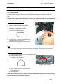
3.1.1- AUTOMATIC PAPER LOAD
1) Make sure the TK14 is power supplied.
2) Open the printing head and remove paper
from inside the mechanism (if there is any).
3) Make sure that the platen is closed.
4) Make sure the paper end is cut in a straight
way as shown in the next figure:
5) Put the paper end in the mechanism inlet.
6) Push the paper in until the TK14 detects it and
starts the auto-load sequence.
7) Wait until the auto-load sequence extracts the
paper from the printer outlet.
Fig.3.1- Automatic paper load.
NOTE:
In the automatic paper load, the printer motor runs at low speed, because the printer needs the
maximum motor torque. Running at low speed, the motor is noisier, but it is not a wrong performing.
3.1.2- MANUAL PAPER LOAD
1) Open the platen and remove the paper (if there is any).
2) Keep the platen opened.
3) Make sure the paper end is cut in a sharp way
as shown in the next figure:
Fig.3.2- Platen opened.
4) Put the paper end in the mechanism inlet.
5) Push the paper in until it reaches the mechanism
outlet (about 3 cm).
6) Close the platen.
NOTE: After the paper has been loading, push the PFEED button and pick up the ticket, leaving
the next ticket ready to be printed on the top.
19/65
FENIX IMVICO
TK14 OPERATION MANUAL
3.2- BUTTONS FUNCTIONS
PFEED
BUTTON
PROG
BUTTON
LED indicator
Fig. 3.3- TK14 led and buttons.
1) PFEED Button.
Functions:
• If pressed on start-up, it activates the SELF-TEST MODE.
• If pressed together with PROG button on start-up, they activate the HEXADECIMAL MODE.
• During PROGRAMMING MODE this is the “YES” button.
• Paper feeding using the paper FEED button cannot be performed under the following
conditions:
• The paper roll end sensor detects a paper end.
• When the printer thermal head is opened.
2) PROG Button.
Functions:
• If pressed on start-up, it activates the PROGRAMMING MODE.
• If pressed together with PFEED button on start-up, they activate the HEXADECIMAL DUMP
MODE.
• During PROGRAMMING MODE this is the “NO” button.
3.3- PAPER SENSORS
The TK14 has two specific photo sensors for paper: ‘out of paper’ and ‘near-end paper’.
The out of paper sensor has the basic function of informing the printer controller about the existence of
paper (on the printing line). Because there are some actions (as an example, printing without paper) that
could seriously damage the mechanism, this error blocks all the printer activities.
The ‘near-end paper’ sensor detects when the paper roll is near its end of file. This error, by default, does
not stop printing, but through the ESC c 4 command, it can be achieved that the ‘near-end paper’
detection stops the printing. If a 25 mm inner diameter paper roll is used, the sensor will trigger when
10 meters of paper remain (approximately).
The final user can detect these errors by the LED, and the application developer can test them through the
DEL EOT command, being able to act accordingly.
Near-end paper sensor:
sensor will trigger when
10 meters of paper
remain (approximately).
Fig.3.4- Near-end paper sensor localization.
20/65
FENIX IMVICO
TK14 OPERATION MANUAL
3.4- OPEN PLATEN SENSOR
When this sensor detects the opening of the platen, it lights the orange LED, blocking all the activity
related to printing.
NOTE: If TK14 detects no paper or platen open while is printing, the current and the following data
will be lose. The control error must be done before sending any byte data. ( See 3.7.4 and
3.7.5 points, flow diagrams of the error detection).
3.5- LED INDICATOR
TK14 has one indicator led to visually inform the printer status.
The led lights GREEN whether the TK14 is powered on without errors.
The led lights ORANGE whether the TK14 does not have paper and/or the platen is opened.
The led lights RED (BLINKING) if there has been any error in the TK14 (See section: 3.7- ERROR
PROCESSING).
3.6- SPECIAL PRINTING MODES
Besides the normal printing mode, in which all the received data are printed according to the settings or
conditions fixed by the commands, the TK14 printer allows two special working modes: the self-test mode,
programming mode and the hexadecimal mode.
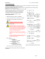
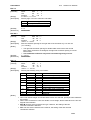
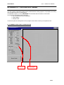
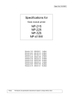
3.6.1- Self-test mode
The TK14 provides the self-test mode with
two different functionality: showing information on the
features of that particular printer model and verifying
the printing.
To enter the self-test mode, the printer must be
powered on while keeping pressed the paper
advance button (FEED).
The TK14 will start printing a report, which
allows checking the features of this particular
model, like the firmware current version, control
functions of the communications protocol, and so on.
If, once this printing has been finished, the
FEED is still kept pressed, the TK14 will start printing
continuously and repetitively a character map
until it finally concludes the self-test by printing
‘* * completed * *’.
This second option of the self-test mode has the goal to
validate the printing speed and quality.
Fig. 3.5- SELF-TEST mode example.
21/65
FENIX IMVICO
TK14 OPERATION MANUAL
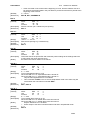
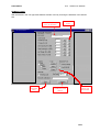
3.6.2- Programming mode
The TK14 has a PROGRAMMING MODE in order to set up some parameters of the printer, without
sending any command neither setting micro-switches.
In this mode, the printer makes some questions to the user. These questions must be answered by
pressing one of the two push buttons.
PFEED button means “YES” and “PROG” button means “NO”.
To start the programming mode, turn off the printer and,
holding the PROG button pressing, turn on the printer.
Then the printer asks for the configurable parameters.
These are the configurable parameters during
PROGRAMMING MODE:
NO
•
Baudrate: 4800, 9600, 19200 or 38400 baud.
YES
•
Parity for serial transmission: ODD, EVEN, NO parity.
•
Cutter mode: total cut, partial cut or passive cut
(no cutter).
NO
Allways select “passive cut” for TK14.
•
Wait until ticket pickup:
NO
Enabling this option, user can not print a new
ticket if the actual printed ticket has not been
picked up; therefore, it can avoid a possible paper
jam. User has to send the GS V command at the
ticket end. While TK14 is waiting the ticket pick
up, BUSY signal will remain active (BUSY=1).
This option is enabled by default.
NO
YES
NO
Alternately, user can make this control himself,
by the DEL EOT command, testing the ticket pick
up flag.
Any way, application programmer has to estimate
the property application consequences and
choose the correct option.
•
•
Paper quality:
a) Normal paper
TF50KS-E2D
TF77KS-E2 (or similar)
b) Wide temperature paper
TL51KS-R2
TL69KS-R2 (or similar)
c) High sensitive paper
TL69KS-HG76 (label paper)
YES
NO
Fig. 3.6- PROGRAMMING MODE example.
Carry Return: Enable / Disable CR command.
Next figure shows how the printer asks for the configurable
parameters:
22/65
FENIX IMVICO
TK14 OPERATION MANUAL
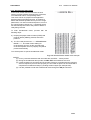
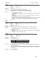
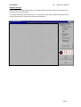
3.6.3- Hexadecimal dump mode
In this mode, all the data received from the host
system is printed, without processing any command,
in hexadecimal and its corresponding ASCII.
This mode can be very helpful for the application
developer during the setup test time, as it allows to
detect and eliminate possible errors (as out of range
parameters, non valid command sequences, errors in
the communication channel, etc.), comparing what it
has theoretically been sent to the printer to what it is
really being received.
To enter hexadecimal mode, proceed with the
following steps:
a) Keeping the paper advance button (FEED) and
program button (PROG) pressed, switch the
power on.
b) The TK14 will print the text ‘~~~~HEXADECIMAL
MODE~~~~’, and it will remain waiting for
receiving data. As soon as the received bytes
received complete one line (9 bytes), they will be
printed automatically.
Turn off the printer to quit the hexadecimal mode.
Fig. 3.6- HEXADECIMAL DUMP mode example.
NOTES:
(1) For any received characters that are under 20h, the ASCII ‘.’ will be printed.
(2) During the hexadecimal dump mode, the DEL EOT command does not work.
(3) It must be taken into account that if the number of bytes is not bigger than the minimum
amount required to print one line (9 bytes), the TK14 will not print. It is recommended to
complete the hexadecimal dump by sending at least 9 bytes (for example 00h).
(4) It is also possible to enter the hexadecimal mode through the GS ( A command.
23/65
FENIX IMVICO
TK14 OPERATION MANUAL
3.7- ERROR PROCESSING
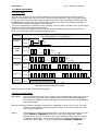
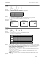
3.7.1- Error types
When an error happens, the TK14 visually notifies the error type through the led, located next to the
buttons. This fact allows the final user to have a direct and visual reference on the current printer status.
On the other hand, the printer status and all its possible errors can also be obtained via software through
the DEL EOT command. In this way, the application developer can have more complete information on
the printer status, therefore being able to act accordingly.
The errors detected by the interface are the following: ‘near-end paper’, hardware error, power supply
voltage error and printing head temperature error.
When any of these errors happen, the led blinks with a different blinking timing sequence for each of
them. If no error happens the led will light permanently green.
Sequence (RED BLINKING)
(a = 0,5 seconds , b = 2 seconds.)
ERROR
‘NEAR-END
PAPER’
a
Led ON
Led OFF
b
1
1
t
PAPER
JAM
Led ON
Led OFF
2
2
t
Led ON
HARDWARE
VOLTAGE
ERROR
Led OFF
4
4
t
Led ON
6
6
Led OFF
t
Led ON
TEMPERATURE
7
7
Led OFF
t
Led ON
No Paper /
Platen open Led OFF
Orange (no blinking)
t
Fig. 3.8- LED Blinking sequence (RED).
More information on these errors can be found below:
NEAR-END PAPER ERROR
[Description]
This error happens when the ‘near-end paper’ sensor detects that the paper roll is close to
be finished. This means that using a paper roll with an external diameter of 80 mm and
inner diameter of 25 mm, the sensor will trigger the error when there are still 10 meters of
paper approximately.
[Recover action]This indication should be really taken as a warning, not as an error as such. The action
depends on the application and the developer’s criteria. To recover from this error, user
must change the paper roll.
[Notes]
Depending on the settings of command “ESC c 4” this error stops the printing or not (see
point 4. CONTROL COMMANDS). If this error is set to stop the printing, it will be
detected as any other error. If this error is not set to stop the printing, user must detect it
by polling the status bytes. This error is indicated in the parallel port depending on the
conditions set by the ”ESC c 3” command (See point 4. CONTROL COMMANDS).
24/65
FENIX IMVICO
TK14 OPERATION MANUAL
HARDWARE ERROR
[Description]
At initialization, the printer internally checks its hardware devices. If they do not function
properly, an error occurs.
[Recover action] This error cannot be recovered. One of the control board components might be damaged
and should be replaced or repaired.
POWER SUPPLY VOLTAGE ERROR
[Description]
The power supply voltage is out of range (12V to 24V DC + 10%).
[Recover action] This is a recoverable error. Unplug the power supply from the printer and check if the
output voltage of the power supply is within the specified range. Replace it in case it is
not working properly.
[Note]
When this error occurs, some parts of the printer may be damaged. If this happens, the
printer will be unable to recover itself and some of its components are likely to be
replaced.
THERMAL HEAD TEMPERATURE ERROR
[Description]
Due to very continuous use of the printer, or due to environmental conditions, the
temperature in the thermal head may reach levels (above 80ºC), which can damage the
printer itself. When this situation occurs, an error must be indicated in order to protect the
printer from abrasion.
[Recover action] The printing recovers automatically from this error when the thermal print head
temperature drops below 60ºC again.
[Note]
This error can happen if the ambient temperature is very high and the printer is working
continuously with high-density printing.
NO PAPER ERROR
[Description]
The out of paper sensor detects there is not paper on the printing line.
[Recover action] This error disappears loading a new paper roll in the printer (see section 3.1. Paper
loading).
[Note]
This error stops the printing and it cannot be restarted until it is not recovered.
This error is indicated in the parallel port depending on the conditions set by
the ”ESC c 3” command (See point 4. CONTROL COMMANDS).
PLATEN OPENED ERROR
[Description]
The platen unit is open.
[Recover action] This error disappears when closing the platen.
[Note]
This error stops the printing and it cannot be restarted until it is not recovered.
This error is indicated in the parallel port depending on the conditions set by
the ”ESC c 3” command (See point 4. CONTROL COMMANDS).
25/65
FENIX IMVICO
TK14 OPERATION MANUAL
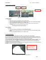
PAPER JAM ERROR
[Description]
When printing a ticket, the paper must run across the printer mechanism and the
presenter unit without any obstacle. Moreover, the ticket has to be the minimum length
in order to the user may catch it.
•
•
IMPORTANT NOTES:
THE MINIMUM TICKET LENGTH IS 120 mm.
ANY TICKET WITH LENGTH MINOR THAN 120 mm WILL CAUSE PAPER JAM.
FENIX SUGGEST A 160 mm MAXIMUM TICKET LENGTH TO AVOID VANDALIC
ACTIONS.
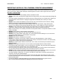
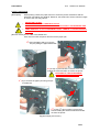
[Recover action] This is a Non-recoverable error.
User must turn OFF the printer and remove the paper jam.
st
1 ) Open the platen and try to remove
the jam pulling the paper backwards.
st
nd
2 ) If step 1 ) has not effect: remove the 2 screws
holding the cutter and take out it from the printer.
BE CAREFUL! THE SHAPPENING
BLADE MEY CAUSE DAMAGE
rd
3 ) Try to remove the paper jam using forceps
or similar tool.
rd
rd
4 ) If step 3 ) has not effect: remove the 4
screws holding the head mechanism and take
out from the printer.
Fig. 3.9- Paper jam recovery.
26/65
FENIX IMVICO
TK14 OPERATION MANUAL
3.7.2- Printer operation when an error happens
When the TK14 detects an error (except the near-end paper), it executes the following operations:
• It stops all printing operations.
• The red led blinks or orange permanently lights.
3.7.3- Data reception error (serial interface only)
If one of the following errors happens during the serial interface data communication, the printer prints
‘?’ or ignores the data.
• Parity error.
• Synchronization error.
• Overlap error.
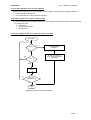
3.7.4- Flow diagram of the error detection for the serial port
BEGINNING
NO
nDTR = 0
SEND COMMAND
DEL EOT
YES
NO
nRTS = 0
READS THE PRINTER
STATUS AND IDENTIFIES
THE ERROR
YES
SENDS
1 BYTE
NO
END OF
TRANSMISSION
YES
END
Fig.3.10- Serial port error flow diagram.
27/65
FENIX IMVICO
TK14 OPERATION MANUAL
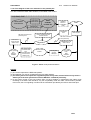
3.7.5- Flow diagram of the error detection for the parallel port
The TK14 meets the IEEE-1284 standard, in the nibble mode variant.
Compatibility mode
Host system
Data transfer
PERIPHERAL
Data transfer
HOST
SYSTEM.
Forward idle
PERIPHERAL
Busy,ACK,PE,/ERR
Interface
returns to
compatibility
mode
END
Negotiation
error
DEL EOT command not
previously sent
HOST SYSTEM
END request
HOST SYSTEM requires
reverse transfer
DEL EOT command
send previously
PERIPHERAL
does not have
data to send
Host system
busy
Data not
available
PERIPHERAL has
data to send
Negotiation
Host system does
not receive data
byte.
Peripheral does
not have more
data to send
Reverse data
transfer
Host system
requires
data byte
Host system
busy.
Data
available
Fig.3.11- Nibble mode phase transitions.
NOTES:
(1) The circles represent the IEEE1284 phases.
(2) This diagram can not be considered as the true state diagram.
(3) The host system can request the negotiation phase at any time, but the TK14 will only return a
status byte if the host system has send the DEL EOT command previously.
(4) If the printer control of the host system does not have enabled or implemented the nibble mode
according to the IEEE-1284 interface, only the compatibility mode will make communication possible.
In this case, the error signaling is reduced to the information provided by the PError and nFault pins.
28/65
FENIX IMVICO
TK14 OPERATION MANUAL
4 – CONTROL COMANDS
4.1- COMMAND NOTATION
[Name]
[Format]
[Range]
[Description]
[Notes]
[Defect]
[Reference]
[Examples]
The command name.
The coding sequence.
It provides the allowed range for the arguments.
It describes the command functionality.
It provides important information in command usage and warnings, if needed.
It provides the default values, if any, for the command parameters.
It lists related commands.
It shows examples on how to use the command.
4.2- TERM DEFINITIONS
1) Receiving buffer.
It is the buffer that stores the received data (commands and data). They are stored temporally in
the buffer and are sequentially processed later.
2) Printing buffer.
The printing buffer is a buffer that holds the data of the image to be printed.
3) Printable area.
It is the maximum range in which the printing is possible under the printer specifications.
The printable area for this printer is the following:
" The horizontal direction length is 48 mm.
4) Inch
Length unit. One inch is 25.4 millimeters.
5) MSB
Most significant bit.
6) LSB
Least significant bit.
7) Base line.
Standard position where the characters are printed. The following drawing shows the position of
normal characters in standard mode:
✻1. When the font selected is A type (12x24 dots), this height is 18 dots.
When the font selected is B type (8x16 dots), this height is 14 dots.
29/65
FENIX IMVICO
TK14 OPERATION MANUAL
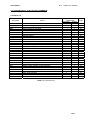
4.3- DESCRIPTION OF THE CONTROL COMMANDS
Command List
Command
LF
CR
DLE EOT
ESC t
ESC SP
ESC !
ESC 2
ESC 3
ESC @
ESC E
ESC G
GS B
ESC J
ESC M
ESC a n
ESC c 3
ESC c 5
ESC d
GS !
GS ( A
GS L
GS T
GS V
GS f
GS H
GS h
GS k
GS w
GS v 0
FS p
FS q
Name
Print and line feed
Print and carriage return
Real-time status transmission
Select character code table
Set right-side character spacing
Select print mode(s)
Select default line spacing
Set line spacing
Initialize printer
Turn emphasized mode on/off
Turn double-strike mode on/off
Turn white/black reverse printing mode on/off
Print and feed paper
Select character font
Select justification
Select paper sensor to output PE signal
Enable/disable panel buttons
Print and feed n lines
Select character size
Execute test print
Set left margin
Set print position to the beginning of print line
Feed paper to cut paper line
Select font for HRI characters
Select printing position of HRI characters
Set bar code height
Print bar code
Set bar code width
Print raster bit image
Print NV bit image
Define NV bit image
Command
classification
Executing
Setting
X
X
X
X
X
X
X
X
X
X
X
X
X
X
X
x
X
X
X
X
X
X
X
X
X
X
X
X
X
X
X
X
Table 4.1- Command List.
30/65
Page
31
31
31
33
33
33
34
34
34
34
34
35
35
35
36
36
37
37
37
38
38
39
39
39
40
40
40
42
42
43
44
FENIX IMVICO
LF
[Name]
[Format]
[Description]
[Note]
[Reference]
CR
[Name]
[Format]
[Description]
[Notes]
[Reference]
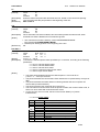
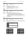
DLE EOT n
[Name]
[Format]
[Range]
[Description]
[Notes]
TK14 OPERATION MANUAL
Print and line feed
ASCII
LF
Hex
0A
Decimal
10
Prints the data in the print buffer and feeds one line, based on the current line spacing.
This command sets the print position to the beginning of the line.
ESC 2, ESC 3.
Print and carriage return
ASCII
CR
Hex
0D
Decimal
13
When automatic line feed is enabled, this command operates the same as LF; when
automatic line feed is disabled, this command is ignored.
• This command is set at the start-up, via the PROGRAMMING MODE
(see point 3.6.2- PROGRAMMING MODE).
• Sets the print starting position to the beginning of the line.
LF
Real-time status transmission
ASCII
DLE EOT n
Hex
10
04 n
Decimal
16
04 n
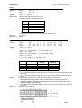
<01>H ≤ n ≤ <04>H
Transmits the selected printer status specified by n in real-time, according to the following
parameters:
n = <01>H: Transmit printer status
n = <02>H: Transmit offline status
n = <03>H: Transmit error status
n = <04>H: Continuous paper sensor status
n = <05>H: Paper sensor status
• The status is transmitted whenever the data sequence <10>H<04>H<n>
( <01>H ≤ n ≤ <05>H) is received.
• The printer transmits the current status. Each status item is represented by one-byte of
data.
• The printer transmits the status without confirming whether the host computer can
receive data (in serial interface).
• The printer executes this command upon receiving it.
• This command is executed even when the printer is offline, the receiver buffer is full, or
there is an error status with a serial interface model.
• If a not recovery error occurred, the bit 2 in the Printer Status (n=1) will be
indeterminate.
n = <01>H: Printer status
Bit
0
1
2
3
4
5
6
7
OFF/ON
OFF
ON
OFF
OFF
ON
ON
OFF
ON
OFF
Function
Not used. Fixed to OFF
Not used. Fixed to ON
Not used. Fixed to OFF
Online
Offline
Not used. Fixed to ON
Does not wait for online error recovery
Waits for online error recovery
Undefined
Not used. Fixed to OFF
31/65
FENIX IMVICO
TK14 OPERATION MANUAL
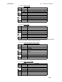
n = <02>H: Offline status
Bit
0
1
2
3
4
5
6
7
OFF/ON
OFF
ON
OFF
ON
ON
OFF
ON
OFF
ON
OFF
Function
Not used. Fixed to OFF
Not used. Fixed to ON
Platen is closed (Thermal head is closed)
Platen is open (Thermal head is open)
Undefined
Not used. Fixed to ON
No paper-end stop
Printing is being stopped
No error
Error occurred
Not used. Fixed to OFF
n = <03>H: Error status
Bit
0
1
2
3
4
OFF/ON
Function
OFF
Not used. Fixed to OFF
ON
Not used. Fixed to ON
OFF
Not used. Fixed to OFF
x
Not used.
ON
Not used. Fixed to ON
OFF
No unrecoverable error
5
ON
Unrecoverable error occurred
OFF
No auto-recoverable error
6
ON
Auto-recoverable error occurred
7
OFF
Not used. Fixed to OFF
Bit 6: Bit 6 is ON when printing is stopped due to high print head temperature
until the print head temperature drops sufficiently.
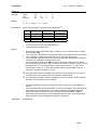
n = <04>H: Continuous paper sensor status
Bit
0
1
2
3
4
5
6
7
OFF/ON
OFF
ON
OFF
ON
ON
OFF
OFF
Function
Not used. Fixed to OFF
Not used. Fixed to ON
Undefined
Paper near-end sensor: Paper present
Paper near-end sensor: Paper not
present
Not used. Fixed to ON
Undefined
Paper real-end sensor: Paper present
Paper real-end sensor: Paper not present
Not used. Fixed to OFF
n = <05>H: Paper sensor status
Bit
0
1
2
3
4
5
6
7
OFF/ON
OFF
ON
OFF
ON
ON
OFF
Function
Not used. Fixed to OFF
Not used. Fixed to ON
Undefined
Ticket not pick up
Ticket pick up
Not used. Fixed to ON
Undefined
Undefined
Not used. Fixed to OFF
32/65
FENIX IMVICO
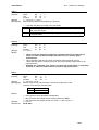
ESC t n
[Name]
[Formato]
[Range]
[Description]
TK14 OPERATION MANUAL
Select character code table
n
ASCII
ESC
t
n
Hex
1B
74
Decimal
27
116 n
n=<00>H , n = <11>H
Selects page n from the character code table.
n
0
17
[Default]
[Reference]
ESC SP n
[Name]
[Format]
[Range]
[Description]
[Notes]
[Default]
[Reference]
ESC ! n
[Name]
[Format]
[Range]
[Description]
n=0
APPENDIX F
Set right-side character spacing
ASCII
ESC SP n
Hex
1B 20 n
Decimal
27 32 n
<00>H ≤n≤ <FF>H
Sets the character spacing for the right side of the character to [n x 0.125 mm
(n x 0.0049”)].
• The right side character spacing for double-width mode is twice the normal
value. When characters are enlarged, the right-side character spacing is n times
normal value.
• This command is effective only when sent at the beginning of a line.
n = <04>H
APPENDIX A
Select print mode(s)
n
ASCII
ESC !
Hex
1B
21 n
Decimal
27
33 n
<00>H ≤ n ≤ <FF>H
Selects print mode(s) using n as follows:
Bit
0
1
2
3
4
5
6
7
[Notes]
Page
PC437 (U.S.A., standard Europe)
PC866 (Cyrillic)
OFF/ON
OFF
ON
--OFF
ON
OFF
ON
OFF
ON
---
Hex
00
01
--00
08
00
10
00
20
---
Function
Character font A (12 x 24).
Character font B (8 x 16).
Undefined.
Undefined.
Emphasized mode not selected.
Emphasized mode selected.
Double-height mode not selected.
Double-height mode selected.
Double-width mode not selected.
Double-width mode selected.
Undefined.
Undefined.
• When both double-height and double-width modes are selected, quadruple-size characters
are printed.
• When some characters in a line are double or more height, all the characters in the line are
aligned at the baseline.
• ESC M can also select character font type. However, the setting of the last
received command is effective.
• GS ! can also select character size. However, the setting of the last received
command is effective.
33/65
FENIX IMVICO
[Default]
[Reference]
ESC 2
[Name]
[Format]
[Description]
[Reference]
ESC 3 n
[Name]
[Format]
[Range]
[Description]
[Default]
[Reference]
ESC @
[Name]
[Format]
[Description]
[Notes]
ESC E n
[Name]
[Format]
[Range]
[Description]
[Notes]
[Default]
[Reference]
ESC G n
[Name]
[Format]
[Range]
[Description]
[Notes]
[Default]
[Reference]
TK14 OPERATION MANUAL
• If this command is not received at the beginning of a line, and the character font is to
be changed, all previous data in the print buffer is printed and the ticket is placed at the
beginning of the next line..
n = <00>H
ESC M, GS !, APPENDIX A
Select default line spacing
ASCII
ESC 2
Hex
1B 32
Decimal
27 50
Selects 0.93 mm (15 x 0.0625 mm) line spacing.
ESC 3.
Set line spacing
ASCII
ESC 3 n
Hex
1B
33 n
Decimal
27
51 n
<00>H ≤ n ≤ <FF>H
Sets the line spacing to [n x 0.0625 mm].
n = 15
ESC 2
Initialize printer
ASCII
ESC @
Hex
1B
40
Decimal
27
64
Clears the data in the print buffer and resets the printer settings to the settings that were
in effect when the power was turned on.
The data in the receiver buffer is not cleared.
Turn emphasized mode on/off
n
ASCII
ESC
E
n
Hex
1B
45
n
Decimal
27
69
0 ≤ n ≤ 255
Turns emphasized mode on or off
When the LSB of n is 0, emphasized mode is turned off.
When the LSB of n is 1, emphasized mode is turned on.
Only the least significant bit of n is enabled.
• This command and ESC ! turn on and off emphasized mode in the same way. Be
careful when this command is used with ESC !.
n=0
ESC !, ESC G
Turn on/off double-strike mode
n
ASCII
ESC
G
n
Hex
1B
47
n
Decimal
27
71
0 ≤ n ≤ 255
Turns double-strike mode on or off.
When the LSB of n is 0, double-strike mode is turned off.
When the LSB of n is 1, double-strike mode is turned on.
Only the lowest bit of n is enabled.
• Printer output is the same in double-strike mode and in emphasized mode.
n=0
ESC E
34/65
FENIX IMVICO
GS B n
[Name]
[Format]
[Range]
[Description]
[Notes]
[Default]
ESC J n
[Name]
[Format]
[Range]
[Description]
[Notes]
ESC M n
[Name]
[Format]
[Range]
[Description]
TK14 OPERATION MANUAL
Turn white/black reverse printing mode
n
ASCII
GS
B
n
Hex
1D
42
n
Decimal
29
66
0 ≤ n ≤ 255
Turns on or off white/black reverse printing mode.
When the LSB of n is 0, white/black reverse mode is turned off.
When the LSB of n is 1, white/black reverse mode is turned on.
•
•
Only the lowest bit of n is valid.
When white/black reverse printing mode is on, it also applied to character spacing set
by ESC SP.
• This command does not affect bit image, user-defined bit image, bar code and HRI
characters.
• This command does not affect the space between lines.
• White/black reverse mode has a higher priority than underline mode. Even if underline
mode is on, it is disabled (but not cancelled) when white/black reverse mode is
selected.
n=0
Print and feed paper
n
ASCII
ESC J
Hex
1B 4A n
n
Decimal
27 74
<00>H ≤ n ≤ <FF>H
Prints the data in the print buffer and feeds the paper [n x 0.125 mm (0.0049”)].
• After printing is completed, this command sets the print starting position to the
beginning of the line.
• The paper feed amount set by this command does not affect the values set by ESC 2
or ESC 3.
• The printer uses the vertical motion unit (y).
Select character font
ASCII
ESC M
Hex
1B
4D
Decimal
27
77
n = <00>H, <01>H
Selects the character font.
n
<00>H
<01>H
[Notes]
[Reference]
n
n
n
Function
Character Font A (12 x 24) selected
Character Font B (8 x 16) selected
• ESC ! can also select character font types. However the setting of the last received
command is effective.
• This command must be sent at the beginning of a line. If it is sent in the middle of a line,
all previous data in the print buffer is printed and the ticket is placed at the beginning of
the next line.
ESC !, APPENDIX A
35/65
FENIX IMVICO
ESC a n
[Name]
[Format]
[Range]
[Description]
TK14 OPERATION MANUAL
Select justification
n
ASCII
ESC
a
n
Hex
1B
61
n
Decimal
27
97
≤
≤
≤
≤
n
n
0
2, 48
50
Aligns all the data in one line to the specified position
n selects the justification as follows:
n
0, 48
1, 49
2, 50
[Notes]
•
•
[Reference]
[Example]
Justification
Left justification
Centering
Right justification
The command is enabled only when processed at the beginning of the line.
This command executes justification in the printing area.
ESC !
Left justification
Centering
ABC
ABCD
ABCDE
ESC c 3 n
[Name]
[Format]
[Range]
[Description]
1
2
3
4-7
•
•
•
•
•
[Default]
ABC
ABCD
ABCDE
ABC
ABCD
ABCDE
Select paper sensor(s) to output paper end signals (PE in parallel interface)
n
ASCII
ESC
c
3
n
Hex
1B
63
33
n
Decimal
27
99
51
0 ≤ n ≤ 255
Selects the paper sensor(s) to output paper end signals.
Each bit of n is used as follows:
Bit
0
[Notes]
Right justification
OFF / ON
OFF
ON
OFF
ON
OFF
ON
OFF
ON
-
Hex
00
01
00
02
00
04
00
08
-
Function
Paper roll near-end sensor disabled
Paper roll near-end sensor enabled
Paper roll near-end sensor disabled
Paper roll near-end sensor enabled
Paper roll end sensor disabled
Paper roll end sensor enabled
Paper roll end sensor disabled
Paper roll end sensor enabled
Undefined
The command is available only with a parallel interface and is ignored with a serial interface.
It is possible to select multiple sensors to output signals. Then, if any of the sensors detects
a paper end, the paper end signal is output.
Sensor is switched when executing this command. The paper end signal switching be
delayed depending on the receive buffer state.
If either bit 0 or bit 1 is on, the paper roll near-end sensor is selected as the paper sensor
outputting paper-end signals
If either bit 2 or bit 3 is on, the paper roll end sensor is selected as the paper sensor
outputting paper-end signals.
When all the sensors are disabled, the paper end signal always outputs a paper present
status.
n = 12
36/65
FENIX IMVICO
TK14 OPERATION MANUAL
ESC c 5 n
[Name]
[Format]
Enable/disable panel buttons
n
ASCII
ESC c
5
Hex
1B
63 35 n
Decimal
27
99 53 n
≤
≤
n
[Range]
0
255
[Description]
Enables or disables the panel buttons.
• When the LSB of n is 0, the panel buttons are enabled.
• When the LSB of n is 1, the panel buttons are disabled.
[Notes]
Only the lowest bit of n is valid.
• In this printer, only the FEED button can be disable.
n=0
[Default]
ESC d n
[Name]
[Format]
[Range]
[Description]
[Notes]
[Reference]
GS ! n
[Name]
[Format]
[Range]
[Description]
Print and feed n lines
n
ASCII
ESC
d
n
Hex
1B
64
n
Decimal
27
100
<00>H ≤ n ≤ <FF>H
Prints the data in the print buffer and feeds n character lines.
This command sets the print starting position to the beginning of the line.
• This command does not affect the line spacing set by ESC 2 or ESC 3.
• The maximum paper feed amount is 1016 mm {40”}. If the paper feed amount (n x line
spacing) of more than 1016 mm {40”} is specified, the printer feeds the paper only
1016 mm {40”}.
• Every line feed corresponds to the current selected font height (24 dots for Font A and
16 dots for Font B).
ESC 2, ESC 3.
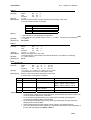
Select character size
n
ASCII
GS
!
Hex
1D
21 n
Decimal
29
33 n
<00> ≤ n ≤ <FF>H (1 ≤ vertical number of times ≤ 8, 1 ≤ horizontal number of times ≤ 8)
Selects the character height using bits 0 to 3 and selects the character width using bits 4
to 7, as follows:
Bit
0
1
2
3
4
5
6
7
OFF / ON
Hex
Function
Character height selection. See Table 2.
Character width selection. See Table 1.
Table 1
Character Width Selection
Hex
Width
00
1 (normal)
10
2 (double-width)
20
3
30
4
40
5
50
6
60
7
70
8
Table 2
Character Height Selection
Hex
Height
00
1 (normal)
01
2 (double-height)
02
3
03
4
04
5
05
6
06
7
07
8
37/65
FENIX IMVICO
[Notes]
TK14 OPERATION MANUAL
• This command is effective for all characters, except for HRI characters.
• The vertical direction is the paper feed direction, and the horizontal direction is
perpendicular to the paper feed direction.
• When characters are enlarged with different sizes on one line, all the characters on the
line are aligned at the baseline.
• The ESC ! command can also turn double-width and double-height modes on or off.
However, the setting of the last received command is effective.
n = <00>H
ESC !, APPENDIX A
[Default]
[Reference]
GS ( A pL pH n m
[Name]
Execute test print
pL pH n
m
[Format]
ASCII
GS (
A
m
Hex
1D 28
41 pL pH n
m
Decimal
29 40
65 pL pH n
[Range]
(pL + (pH x 256)) = 2 (where pL = <02>H, pH = <00>H)
<30>H ≤ n ≤ <32>H
<31>H ≤ m ≤ <33>H
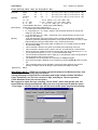
[Description] Executes a test print with a specified test pattern on a specified paper.
• pL, ph specifies (pL+(phx256)) for the number of the bytes after ph (n and m).
• n specifies the paper to be tested.
n
<30>H
<31>H
<32>H
•
m specifies a test pattern.
m
<31>H
<32>H
<33>H
[Details]
•
GS L nL nH
[Name]
[Format]
[Range]
[Description]
Paper
Paper roll
Test pattern
Hexadecimal dump
Printer status print
Rolling pattern print
This command has enabled only when processed at the beginning of a line.
After the test print is finished, the printer resets itself automatically. Therefore, data
already defined before this command is executed, such as user-defined buffer and print
buffer are cleared; and each setting returns to the default value.
Set left margin
nL nH
ASCII
GS L
Hex
1D 4C nL nH
nL nH
Decimal
27 76
<00>H ≤ nL ≤ <FF>H
<00>H ≤ nH ≤ <FF>H
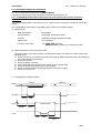
Sets the left margin using nL and nH.
• The left margin is set to [(nL + nH x 256) x 0.125 mm].
Printable area
Left margin
[Notes]
[Default]
[Reference]
• This command is effective only when processed at the beginning of the line.
• This commands affects text, graphic and bar code printing.
nL = <00>H, nH = <00>H
APPENDIX A
38/65
FENIX IMVICO
GS T n
[Name]
[Format]
[Range]
[Description]
TK14 OPERATION MANUAL
Set print position to the beginning of print line
n
ASCII
GS
T
n
Hex
1D
54
n
Decimal
27
84
n = <00>H or n = <01>H
Sets the print position to the beginning of print line.
• n specifies the data processing in the print buffer.
n
Printing position
<00>H Sets the print position to the beginning of print line after deleting all
data in the print buffer.
<01>H Sets the print position to the beginning of print line after printing all data
in the print buffer.
GS V m
[Name]
[Format]
[Range]
[Notes]
Feeds paper to the passive cutter line.
m
ASCII
GS V
m
Hex
1D 56
m
Decimal
27 86
m = <01>H
•
•
•
GS f n
[Name]
[Format]
[Range]
[Description]
There are 26 mm of distance between the thermal head line and the passive
cutter line. This command arranges the ticket to be cut, feeding paper
automatically.
This command is effective only when processed at the beginning of a line.
Afterwards the ticket is cutting by the user, the printer feeds the paper back to the
printing position.
Sending this command, user informs to TK14 that actual ticket is completely
finished; so TK14 can make internal controls to right performance.
Select font for Human Readable Interpretation (HRI) characters
n
ASCII
GS
f
n
Hex
1D
66
n
Decimal
27
102
n = <00>H or <01>H
Selects a font for the HRI characters used when printing a bar code.
n selects a font from the following table:
n
<00>H
<01>H
[Notes]
[Default]
[Reference]
Font
Font A (12x24)
Font B (8x16)
• HRI indicates Human Readable Interpretation
• HRI characters are printed at the position specified by GS H.
• HRI characters are always printed at X-Scale = 1 and Y-Scale = 1
n = <01>H
GS H, GS k
39/65
FENIX IMVICO
TK14 OPERATION MANUAL
GS H n
[Name]
[Format]
Select print position for HRI characters.
n
ASCII
GS H
Hex
1D 48 n
Decimal
29 72 n
n = 0/3
Selects the print position of HRI characters when printing a bar code.
n selects the print position as follows:
[Range]
[Description]
n
0
1
2
3
[Notes]
[Default]
[Reference]
Printing position
Not printed
Above the bar code
Below the bar code
Both above and below the code bar
• HRI indicates Human Readable Interpretation
• HRI characters are printed using X-scale = 1, Y-scale = 1 and the font specified by GS f.
n = <02>H
GS f, GS k
GS h n
[Name]
[Format]
[Range]
[Description]
[Default]
[Reference]
Select bar code height
n
ASCII
GS
h
n
Hex
1D
68
Decimal
27 104 n
≤
≤
<01>H n <FF>H
Selects the height of the bar code.
n specifies the bar code height in the vertical direction [n x 0.0625 mm (0.0049”)].
n = <A0>H (10mm)
GS k
GS k m n d1...dn
[Name]
Print bar code
m
n
d1...dn
[Format]
ASCII
GS
k
n
d1...dn
Hex
1D
6B m
n d1...dn
Decimal
27
107 m
[Range]
m= <43>H , m = <45>H, m= <46>H or m= <49>H
(n and d depend on the bar code system used).
[Description]
Selects a bar code system and prints the bar code.
m selects a bar code system as follows:
m
<43>H
<45>H
<46>H
<49>H
[Notes]
Bar Code System Number of Characters
Remarks
n = <0C>H
EAN13
<30>H ≤ d ≤ <39>H
CODE39
<01>H ≤ n ≤ <FF>H
<30>H ≤ d ≤ <39>H, <41>H ≤ d ≤
<5A>H, <20>H, <24>H, <25>H,
<2B>H, <2D>H, <2E>H, <2F>H
ITF
<01>H ≤ n ≤ <FF>H
<30>H ≤ d ≤ <39>H
(even number)
Code128
<02>H ≤ n ≤ <FF>H
<00>H ≤ d ≤ <7F>H
• n indicates the number of bar code data bytes, and the printer processes n bytes from
the next character data as bar code data.
• If n is outside the specified range, the printer stops command processing and
processes the following data as normal data.
• If d is outside the specified range, the printer only feeds paper and processes the
following data as normal data.
• If the horizontal size exceeds printing area, the printer only feeds the paper.
• This command feeds as much paper as is required to print the bar code, regardless of
the line spacing specified by ESC 2 or ESC 3.
40/65
FENIX IMVICO
TK14 OPERATION MANUAL
• This command is enabled only when no data exists in the print buffer. When data
exists in the print buffer, the printer processes the data following m as normal data.
• After printing the bar code, this command sets the print position to the beginning of the
line.
• This command is not affected by print modes.
• The number of data for the ITF bar code must be even numbers. When an odd
number of bytes of data is input, the printer ignores the last received data.
• When Code128 (m=49h) is used:
1. Refer to APPENDIX E – CODE 128 BAR CODE for the information for the
Code128 bar code and its code table.
2. When using Code128 in this printer, take the following points into account for data
transmission:
# The top of the bar code data string must be the code set
selection character (CODE A, CODE B or CODE C),
which selects the first code set.
# Special characters are defined by combining two
characters “{“ and one character. The ASCII character “{“
is defined by transmitting “{“ twice consecutively.
Specific character
SHIFT
CODE A
CODE B
CODE C
FNC1
FNC2
FNC3
FNC4
“{“
[Example]
ASCII
{S
{A
{B
{C
{1
{2
{3
{4
{{
Transmit data
Hex
7B, 53
7B, 41
7B, 42
7B, 43
7B, 31
7B,32
7B, 33
7B,34
7B, 7B
Decimal
123, 83
123, 65
123, 66
123,67
123, 49
123, 50
123,51
123, 52
123, 123
Example data for printing “Ref. 258710”
In this example, the printer first prints “No.” Using CODE B, then prints the
following numbers using CODE C.
GS k 73 11 123 66 82 101 102 46 123 67 25 87 10
Fig. 4.1- Code128 code example.
<Others>
[Reference]
3. If the top of the bar code data is not the code set selection character, the printer stops
command processing and processes the following data as normal data.
4. If the combination of “{“ and the following character does not apply any special
character, the printer stops command processing and processes the following data as
normal data.
5. If the printer receives characters that cannot be used in the special code set, the
printer stops command processing and processes the following data as normal data.
6. The printer does not print HRI characters that correspond to the shift characters or
code set selection characters.
7. HRI character for the function character is space.
8. HRI characters for the control character (<00>H to <1F>H and <7F>H) are space.
Be sure to keep spaces on both right and left sides of a bar code. (Spaces are different
depending on the types of the bar code.)
GS h, GS w
41/65
FENIX IMVICO
GS w n
[Name]
[Format]
[Range]
[Description]
[Default]
[Reference]
TK14 OPERATION MANUAL
Set bar code width
n
ASCII
GS
w
n
Hex
1D
77
Decimal
27 119 n
<02>H ≤ n ≤ <06>H
Sets the horizontal size of the bar code.
n specifies the bar code width as follows:
n
Module Width (mm) for
Multi-level Bar Code
<02>H
<03>H
<04>H
<05>H
<06>H
0.250
0.375
0.500
0.625
0.750
• Multi-level bar codes are as follows: EAN13, CODE93, ITF.
n = <03>H
GS k
GS v 0 m xL xH yL yH d1 ... dk
[Name]
Print raster bit image
m
xL
xH yL yH
d1...dk
[Format]
ASCII
GS
v
0
xL
xH yL yH
d1...dk
Hex
1D
76 30 m
xL
xH
yL yH
d1...dk
Decimal
27
118 48 m
[Range]
<00>H ≤ m ≤ <03>H
<00>H ≤ xL ≤ <FF>H
<00>H ≤ xH ≤ <FF>H where 1 ≤ (xL + xH x 256) ≤ 128
<00>H ≤ yL ≤ <FF>H
<00>H ≤ yH ≤ <08>H where 1 ≤ (yL + yH x 256) ≤ 4095
<00>H ≤ d ≤ <FF>H
k = (xL + xH x 256) x (yL + yH x 256) (k ≠ 0)
[Description]
Selects raster bit-image mode. The value of m selects the mode, as follows:
m
[Notes]
[Example]
Mode
Vertical Dot
Density
203.2 dpi
203.2 dpi
101.6 dpi
101.6 dpi
Horizontal Dot
Density
203.2 dpi
101.6 dpi
203.2 dpi
101.6 dpi
<00>H
Normal
<01>H
Double-width
<02>H
Double-height
<03>H
Quadruple
(dpi: dots per 25.4 mm {1"})
• xL, xH, select the number of data bytes (xL+xH x 256) in the horizontal direction for the
bit image.
• yL, yH, select the number of data bits (yL+yH x 256) in the vertical direction for the bit
image.
This command is effective only when there is no data in the print buffer.
• Data outside the printing area is read in and discarded on a byte-by-byte basis.
• The position at which subsequent characters are to be printed for raster bit image is
specified by GS L (Set left margin).
• d indicates the bit-image data. Setting a bit to 1 prints a dot and setting it to 0 does not
print a dot.
When xL + xH x 256 = 64
42/65
FENIX IMVICO
FS p n m
[Name]
[Format]
TK14 OPERATION MANUAL
Print NV bit image
ASCII
FS
Hex
1C
Decimal
28
p
70
112
n
n
n
m
m
m
[Range]
n=1
0 ≤ m ≤ 3, <48>H ≤ m ≤ < 51>H
[Description]
Prints a NV bit image n using the mode specified by m.
m
Mode
0, 48 Normal
1, 49 Double-width
2,50 Double-height
3,51 Quadruple
[dpi: dots per 25.4 mm]
[Notes]
Vertical
Dot Density
203.2 dpi
203.2 dpi
101.6 dpi
101.6 dpi
Horizontal
Dot Density
203.2 dpi
101.6 dpi
203.2 dpi
101.6 dpi
•
•
n is the number of the NV bit image (always 1).
m specifies the bit image mode.
•
NV bit image means a bit image which is defined in a non-volatile memory by FS q
and printed by FS p.
This command is not effective when the specified NV bit image has not been defined.
This command is effective only when there is no data in the print buffer.
This command is not affected by print modes (emphasized, double-strike, underline,
character size, white/black reverse printing, etc.).
If the printing area width set by GS L for the NV bit image is less than one vertical
line, the following processing is performed only on the line in question. However, in NV
bit image mode, one vertical line means 1 dot in normal mode (m =0, 48H) and in
double-height mode (m =2, 50H), and it means 2 dots in double-width mode (m =1,
49H) and in quadruple mode (m=3, 51H).
•
•
•
•
➀ The printing area width is extended to the right in NV bit image mode up to one line
➁
•
•
•
[Reference]
vertically. In this case, printing does not exceed the printable area.
If the printing area width cannot be extended by one line vertically, the left margin is
reduced to accommodate one line vertically.
If the downloaded bit-image to be printed exceeds one line, the excess data is not
printed.
This command feeds dots (for the height n of the NV bit-image) in normal and doublewidth modes, and (for the height n ×2 of the NV bit-image) in double-height and
quadruple modes, regardless of the line spacing specified by ESC 2 or ESC 3.
After printing the bit image, this command sets the print position to the beginning of
the line and processes the data that follows as normal data.
FS q, GS v 0
43/65
FENIX IMVICO
TK14 OPERATION MANUAL
FS q n [xL xH yL yH d1…dk]1…[xL xH yL yH d1…dk]
[Name]
Define NV bit image
n
[xL xH yL yH d1...dk]1...[ xL xH yL yH d1...dk]
[Format]
ASCII
FS
q
n
[xL xH yL yH d1...dk]1...[ xL xH yL yH d1...dk]
Hex
1C
71
n
[xL xH yL yH d1...dk]1...[ xL xH yL yH d1...dk]
Decimal
28
113
n=1
[Range]
xL ≤ 48
xH = 0 (when 1≤ (xL+ xH × 256) ≤ 48)
0 ≤ yL ≤ 255
0 ≤ yH ≤ 1 (when 1≤ (yL+ yH × 256) ≤ 288)
k = (xL+ xH × 256) × (yL+ yH × 256) × 8
0 ≤ d ≤ 255
Total available data area = 16380 bytes (16KB-4Bytes)
[Description]
Define the NV bit image specified by n .
• n specifies the NV bit image number (always 1).
• xL, xH specifies (xL+ xH × 256) × 8 dots in the horizontal direction for the NV bits
image you are defining.
• yL, yH specifies (yL+ yH × 256) × 8 dots dots in the vertical direction for the NV bit
image you are defining.
[Notes]
From the beginning of the processing of this command till the finish, mechanical
operations (including initializing the position of the printer head when the cover is open,
paper feeding by using the FEED button, etc.) cannot be performed.
• NV bit image means a bit image which is defined in a non-volatile memory by FS q
and printed by FS p.
• This command is effective only when processed at the beginning of the line.
• This command is effective when 7 bytes <FS∼yH> is processed as a normal value.
• When the amount of data exceeds the capacity left in the range defined by xL, xH, yL,
yH, the printer processes xL, xH, yL, yH out of the defined range.
• The d indicates the definition data. In data (d) a 1 bit specifies a dot to be printed and
a 0 bit specifies a dot not to be printed.
• The definition area in this printer is a maximum of 16KBytes-4Bytes.
• Once a NV bit image is defined, it is not erased by performing ESC @, reset or power
off.
• This command performs only definition of a NV bit image and does not perform
printing. Printing of the NV bit image is performed by the FS p command.
FS p
[Reference]
IMPORTANT NOTE.- FENIX has provided a powerful utility to his Windows driver, that
makes logo load extremely easy and useful.
Taking advantage of high features in drawing and image handle software like Word,
Paint, PhotoShop, etc. the user can load 1 logo, selecting in “Device operation”
(TK14 Windows driver) the correct option.
We suggest to adjust the logo selecting “Driver mode” option until get the size, the
layout and the arrangement desired. After, the user only must reprint with the option
“Load Logo 1” selected, and the logo will be stored at the same way that last printing.
44/65
FENIX IMVICO
TK14 OPERATION MANUAL
APPENDIX A – SPECIFICATIONS
Printing method
Dot density
Printing direction
Printing width
Character per line (default)
Character spacing (default)
Character structure
Character size (mm)
Character number
Print speed
Paper feed speed
Line spacing (default)
Paper roll
Minimum ticket length
Maximum ticket length suggested
Thermal paper type
Interface (compatible)
Receive buffer
Power supply
Peak current consumption
(64 dots activated)
Life span (at 25ºC )
Activation pulse resistance
Abrasion resistance
Temperature
Overall dimensions (mm)
Weight (without paper)
Thermal line printing
203 dpi x 203 dpi (dpi = dots per inch.
1 inch=25.4mm)
8 dots x mm
Unidirectional with friction feed
48 mm (384 dots)
Font A: 42 Font B: 56
0.5 mm (4 dots)
Font A: 12 x 24 dots (1.5 x 3 mm).
Font B: 8 x 16 dots (1 x 2 mm).
Font A is the default.
Font A
Font B
Standard:
1.5 x 3 Standard:
1x2
Double-width:
3 x 3 Double-width:
2x2
Double-height:
1.5 x 6 Double-height:
1x4
Double width/height: 3 x 6 Double width/height: 2 x 4
Alphanumeric characters: 95
Extended Graphics:
128 per page
High speed mode: up to 62,5 mm/s
(The printing speed could vary automatically depending on
the print head temperature as well as the command
processing and the data transmission speed).
62,5 mm/s (continuous paper feed)
0.99 mm
Width: 58 +0/-1mm
Maximum outside diameter: 80 mm (50 m approx.)
Minimum inner diameter: 25 mm
120 mm
160 mm
At –5ºC to 50ºC # TF50KS-E2D
(59µm paper )
TF77KS-E2
(95µm paper)
TL69KS-HG76 (label paper)
At –30ºC to 70ºC# TL51KS-R2
(High heat-resistant
paper)
TL69KS-R2
(High heat-resistant
paper)
At 5ºC to 40ºC # TW80KK-S
(2-ply thermal paper)
From Nippon Paper
Industries
RS-232C and IEEE 1284 (Nibble mode)
10 Kbytes
12V to 24V DC ± 10%
3A (approx.)
100 millions pulses or more (print ratio=12,5%).
50 Km or more.
Operating: -30 to 70ºC
Storage: -35 to 75ºC, except for paper.
198,3 x 95 x 121,7 (H x W x D)
1 Kg (approx.)
45/65
APPENDIX B – IF1500 CONNECTORS AND BUTTONS
LOW
PAPER
connector
TICKET
PICKUP
connector
IF1500
IFCON1500
Serial RS232 and
Parallel
CENTRONICS
(IEEE1284)
Comunication
connector
INTERCONNECTION
LTP1245
(Seiko)
LINE
THERMAL
PRINTER
MECHANISM
POWER
SUPPLY
connector
PAPER
FEED
BUTTON
ACU6205 (Seiko)
PROG
BUTTON
STATUS
LED
AUTOCUTTER UNIT
APPENDIX C – EXTERNAL APPEARANCE
COTES IN mm
FENIX IMVICO
TK14 OPERATION MANUAL
APPENDIX D – HOW TO ORDER
TK14-58-XX
Special version
: Standard type
xx : custom-made type (under agreement only)
nil
AVAILABLE ACCESORIES
PARTNUMBER
FAPOS-1
FA-40TK
RS232-6
CENTRONIC-7
T58X80X25,4
Description
Power supply close frame
Power supply open frame
Serial cable 1,5m
Centronic cable 1,5m
Standard 80 mm diameter paper roll for 58
48/65
FENIX IMVICO
TK14 OPERATION MANUAL
APPENDIX E – CODE128 BAR CODE
In Code128 bar code system, it is possible to represent 128 ASCII characters and 2-digit numerals using
one bar code character that is defined by combining one the 103 bar code characters and 3 code sets.
Each code set is used for representing the following characters:
E.1 Description of the CODE128 Bar Code
•
Code set A: ASCII characters 00H to 5FH
•
Code set B: ASCII characters 20H to 7FH
•
Code set C: 2-digit numeral characters using one character (100 numerals from 00 to 99)
The following special characters are also available in Code128:
-
SHIFT characters
In code set A, the character just after SHIFT is processed as a character for code set B. In code set
B, the character just after SHIFT is processed as the character for code set A.
SHIFT character cannot be used in code set C.
-
Code set selection character (CODE A, CODE B or CODE C)
This character switches the following code set to code set A, B or C.
-
Function character (FNC1, FNC2, FNC3 or FNC4)
The usage of function characters depends on the application software. In code set C, only FNC1 is
available.
49/65
FENIX IMVICO
TK14 OPERATION MANUAL
E.2 Printable characters in CODE SET A
Character
NUL
SOH
STX
ETX
EOT
ENQ
ACK
BEL
BS
HT
LF
VT
FF
CR
SO
SI
DLE
DC1
DC2
DC3
DC4
NAK
SYN
ETB
CAN
EM
SUB
ESC
FS
GS
RS
US
SP
!
“
#
$
%
&
`
Transmit Data
Hex
Decimal
00
0
01
1
02
2
03
3
04
4
05
5
06
6
07
7
08
8
09
9
0A
10
0B
11
0C
12
0D
13
0E
14
0F
15
10
16
11
17
12
18
13
19
14
20
15
21
16
22
17
23
18
24
19
25
1A
26
1B
27
1C
28
1D
29
1E
30
1F
31
20
32
21
33
22
34
23
35
24
36
25
37
26
38
27
39
Character
(
)
*
+
,
.
/
0
1
2
3
4
5
6
7
8
9
:
;
<
=
>
?
@
A
B
C
D
E
F
G
H
I
J
K
L
M
N
O
Transmit Data
Hex
Decimal
28
40
29
41
2A
42
2B
43
2C
44
2D
45
2E
46
2F
47
30
48
31
49
32
50
33
51
34
52
35
53
36
54
37
55
38
56
39
57
3A
58
3B
59
3C
60
3D
61
3E
62
3F
63
40
64
41
65
42
66
43
67
44
68
45
69
46
70
47
71
48
72
49
73
4A
74
4B
75
4C
76
4D
77
4E
78
4F
79
Character
P
Q
R
S
T
U
V
W
X
Y
Z
[
\
]
^
FNC1
FNC2
FNC3
FNC4
SHIFT
CODEB
CODEC
Transmit Data
Hex
Decimal
50
80
51
81
52
82
53
83
54
84
55
85
56
86
57
87
58
88
59
89
5A
90
5B
91
5C
92
5D
93
5E
94
5F
95
7B,31
123,49
7B,32
123,50
7B,33
123,51
7B,34
123,52
7B,53
123,83
7B,42
123,66
7B,43
123,67
50/65
FENIX IMVICO
TK14 OPERATION MANUAL
E.3 Printable characters in CODE SET B
Character
SP
!
“
#
$
%
&
´
(
)
*
+
,
.
/
0
1
2
3
4
5
6
7
8
9
:
;
<
=
>
?
@
A
B
C
D
E
F
G
Transmit Data
Hex
Decimal
20
32
21
33
22
34
23
35
24
36
25
37
26
38
27
39
28
40
29
41
2A
42
2B
43
2C
44
2D
45
2E
46
2F
47
30
48
31
49
32
50
33
51
34
52
35
53
36
54
37
55
38
56
39
57
3A
58
3B
59
3C
60
3D
61
3E
62
3F
63
40
64
41
65
42
66
43
67
44
68
45
69
46
70
47
71
Character
H
I
J
K
L
M
N
O
P
Q
R
S
T
U
V
W
X
Y
Z
[
\
]
^
`
a
b
c
d
e
f
g
h
i
j
k
l
m
n
o
Transmit Data
Hex
Decimal
48
72
49
73
4A
74
4B
75
4C
76
4D
77
4E
78
4F
79
50
80
51
81
52
82
53
83
54
84
55
85
56
86
57
87
58
88
59
89
5A
90
5B
91
5C
92
5D
93
5E
94
5F
95
60
96
61
97
62
98
63
99
64
100
65
101
66
102
67
103
68
104
69
105
6A
106
6B
107
6C
108
6D
109
6E
110
6F
111
Character
P
Q
R
S
T
U
V
W
X
Y
Z
{
|
}
DEL
FNC1
FNC2
FNC3
FNC4
SHIFT
CODEA
CODEC
Transmit Data
Hex
Decimal
70
112
71
113
72
114
73
115
74
116
75
117
76
118
77
119
78
120
79
121
7A
122
7B,7B
123,123
7C
124
7D
125
7E
126
7F
127
7B,31
123,49
7B,32
123,50
7B,33
123,51
7B,34
123,52
7B,53
123,83
7B,41
123,65
7B,43
123,67
51/65
FENIX IMVICO
TK14 OPERATION MANUAL
E.4 Printable characters in CODE SET C
Character
00
01
02
03
04
05
06
07
08
09
10
11
12
13
14
15
16
17
18
19
20
21
22
23
24
25
26
27
28
29
30
31
32
33
34
35
36
37
38
39
Transmit Data
Hex
Decimal
00
0
01
1
02
2
03
3
04
4
05
5
06
6
07
7
08
8
09
9
0A
10
0B
11
0C
12
0D
13
0E
14
0F
15
10
16
11
17
12
18
13
19
14
20
15
21
16
22
17
23
18
24
19
25
1A
26
1B
27
1C
28
1D
29
1E
30
1F
31
20
32
21
33
22
34
23
35
24
36
25
37
26
38
27
39
Character
40
41
42
43
44
45
46
47
48
49
50
51
52
53
54
55
56
57
58
59
60
61
62
63
64
65
66
67
68
69
70
71
72
73
74
75
76
77
78
79
Transmit Data
Hex
Decimal
28
40
29
41
2A
42
2B
43
2C
44
2D
45
2E
46
2F
47
30
48
31
49
32
50
33
51
34
52
35
53
36
54
37
55
38
56
39
57
3A
58
3B
59
3C
60
3D
61
3E
62
3F
63
40
64
41
65
42
66
43
67
44
68
45
69
46
70
47
71
48
72
49
73
4A
74
4B
75
4C
76
4D
77
4E
78
4F
79
Character
80
81
82
83
84
85
86
87
88
89
90
91
92
93
94
95
96
97
98
99
FNC1
CODEA
CODEB
Transmit Data
Hex
Decimal
50
80
51
81
52
82
53
83
54
84
55
85
56
86
57
87
58
88
59
89
5A
90
5B
91
5C
92
5D
93
5E
94
5F
95
60
96
61
97
62
98
63
99
7B,31
123,49
7B,41
123,65
7B,42
123,66
52/65
FENIX IMVICO
TK14 OPERATION MANUAL
APPENDIX F – INTERNAL CHARACTER TABLES
a) Page 0. PC437: USA, Standard Europe (International Character Set: USA).
53/65
FENIX IMVICO
TK14 OPERATION MANUAL
Page 0 (Continued): 80H to FFH
€
213
54/65
FENIX IMVICO
TK14 OPERATION MANUAL
b) Page 17. PC866: Cyrillic.
55/65
FENIX IMVICO
TK14 OPERATION MANUAL
APPENDIX G – TESTING SOFTWARE
The TK14 printer is delivered together with a Windows-based, testing program. This program is an easy
way to explore the TK14´s main features.
To install the program, run the “SETUP.EXE” file and follow the instructions on the screen.
The program is intended for three purposes:
• PC communication port configuration.
• Printer Status.
• Sample ticket.
These three parts are distinguished in the program main window. And they are explained next.
PC COMMUNICATION PORT CONFIGURATION
TK14 Testing Software
Serial port
configuration
Serial or parallel
port selection
56/65
FENIX IMVICO
TK14 OPERATION MANUAL
PRINTER STATUS
When enabling the printer status window, the program tests the printer’s sensors and notifies every
significant error or printing status.
The program tests the printer’s status once. In some errors, there may be a little time delay from the
moment when the error is produced until the printer notifies it.
TK14 Testing Software
57/65
FENIX IMVICO
TK14 OPERATION MANUAL
SAMPLE TICKET
With this feature, user can appreciate different formats of text by choosing the attributes of the desired
text.
User can change this text
(up to 25 characters)
Attributes to
choose
TK14 Testing Software
TK14 SAMPLE TICKET
Prints the
customized
ticket
Prints an autotest
including the printer
settings
Prints
graphic, logo
and barcode
58/65
FENIX IMVICO
TK14 OPERATION MANUAL
SPAIN c/ Pacífico, 53-55 – 08027 BARCELONA
Phone Num: 34 – 93 353 92 22
Fax Num: 34 – 93 353 97 21
E-mail: [email protected]
http: www.feniximvico.com
59/65