1
Spec. No D-F0301
Specifications for
Kiosk module printer
NP-215
NP-225
NP-325
NP-415W
Revision 1.00 2000.08.01 1 edition
Revision 2.00 2001.04.18 2 edition
Revision 2.10 2001.06.13 3 edition
Revision 2.20 2002.01.29 4 edition
Revision 2.30 2002.02.15 5 edition
Revision 2.40 2002.03.26 6 edition
Revision 2.50 2002.04.12 7 edition
Revision 2.60 2002.07.09 8 edition
Revision 2.70 2003.01.31 9 edition
Notice
All features and specifications described are subject to change without notice.
Read carefully Before Using the Printer
Wrong handling of the printer may cause its performance declined and the product damaged. Please
read the notes below before handling.
1. Static discharge prevention must be made for installation and removal of the printer to protect IC
and other electrical parts. Connect it to the earth ground. It is also requested to remove the static
from body of the person before handling, especially, the input terminal.
2. Avoid excessive force to the input terminal for handling.
3. When any type of paper, other than specified in this manual, is used, it may cause deterioration
of the print quality and thermal head reliability.
Examples of troubles
1) Print quality deterioration by using low sensitivity paper.
2) Thermal head wears due to roughness of paper surface.
3) Sticking between heat receipt layer and thermal head, and vibration noise during printing.
4) Print ink disappears on low print durability paper.
5) Electrolyte corrosion on thermal head due to low quality of heat receipt layer.
4. Avoid printing with no paper loaded. It damages platen and thermal head.
5. Do not scrabble thermal head with sharp edge or something hard, or give impact. The heat
element may be damaged.
6. Set the power of printer off before connecting or removing connecters.
7. When printing in high speed under low temperature of high humidity environment, the paper may
be stained by moisture that appears from paper, or the printer may have condensation. Avoid
dew from dropping down to the thermal head that may cause electrolyte corrosion. Turn the
power off until any dew is removed.
8. The printer is not protected from water or dew formed. Do not water the printer or handle it with a
wet hand, which may cause damage to the printer due to short circuit, or heat or fire.
9. The printer is not protected from dust or dirt. If it is used at dusty place, the thermal head may be
damaged or paper feed is not operated properly.
10. When cleaning the printer with a vacuum cleaner, avoid the printer’s paper outlet from locating
cleaner’s air inlet.
11. The printer’s main structure parts use plated steel. However, rust may be caused to the cut
section.
12. Reflection type of infrared ray sensors are used at some locations in the printer. Direct sun light
may cause mal-function of printer. Avoid from such a location for installation.
13. This printer does not support any operations caused by the commands or control commands not
specified in this manual.
Table of Contents
1. Overview
1.1 Overview
1.2 Features
1.3 Configuration
2. Specifications
2.1 Basic specifications
2.2 Printing area and cutter position
2.3 Power supply specifications
2.4 Reliability
2.5 Dimensions
1) NP-215 dimensional drawing
2) NP-225 dimensional drawing
3) NP-325 dimensional drawing
4) NP-415W dimensional drawing
1
1
2
2
4
5
5
6
7
8
9
3. Interface specifications
3.1 Parallel interface (Centronics)
3.2 Serial interface (RS-232C)
3.3 Connector connections
3.4 Connector signal details
10
11
12
12
4. Functions
4.1 Function setting
4.2 Processing error
4.3 Buffer full print
4.4 Automatic paper cut
4.5 Winder drive
4.6 Partition drive
16
17
17
18
18
18
5. Control commands
5.1 Control command table
5.2 Printer driver
5.3 Control command details
19
20
20
6. Character code table
6.1 Domestic code table
6.2 Overseas character code table
6.3 International character code table
39
40
41
7. Cable
7.1 B501 power cable
42
1. Overview
1.1 Overview
The printer is categorized as following.
NP - *
*
1
2
5
*
*
3
4
1: Paper width, 2 = 2 inches, 3 = 3 inches
2: Paper setting, 1= Paper holder type, 2 = Drop-in type
3: Interface, P = Parallel, R = Serial, D = Parallel/Serial compatible
4: OEM number
* D type is parallel and serial compatible. Interface connector is not incorporated.
NP -
415
W
*
*
1
2
3
1: Windows driver available
2: Interface, P = Parallel, R = Serial, D = Parallel/Serial compatible
3: OEM number
* D type is parallel and serial compatible. Interface connector is not incorporated.
1.2 Features
This module printer is designed on the basis of our long experience as a printer manufacturer.
Individual unit such as printer mechanism, controller board and auto-cutter is assembled in
compact with our reliable design concept.
Simple integration to the system requiring only power and data supplies, that contributes to the
short development time and improvement of product reliability.
1) Important areas such as paper entrance and auto-cutter guide are designed professionally on
the basis of our long experience as a printer manufacturer.
2) Small, compact and light weight. Easy to integrate into various kinds of system.
3) Short development time.
4) High speed and quality of printing
5) Both parallel and serial interfaces are available as a standard.
6) Various barcode symbols, 1-D and 2-D (QR code) are available.
7) Various kinds of application are available.
8) Possible to control paper presenter (paper transfer and present device).
9) User-friendly drop-in type of roll paper holder with paper end sensor. * 1
10) Windows drivers (Windows95/98/NT4.0/2000) are available.
11) Easy to write/rewrite F/W by using flash memory. Also, 3 patterns of registration are
available with NV bit image.
*1 Drop-in type of paper holder is for NP-225, NP-325 and NP-415W. NP-215 is paper holder
type.
1
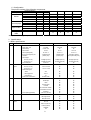
1.3 Configuration
The printer consists of the following components.
Product Name
Description
Specification
Part No.
Q’ty
NP-215
1
NP-225
1
Printer
NP-325
1
NP-415W
1
24-X117
1
60xØ 48mm
24-X121
1
Thermal paper
80xØ 48mm
24-X116
1
112xØ 48mm
80R
35-029Q
1
Paper holder
80L
35-030Q
1
Screws
tight
21-U196
2
B501power
D-P44507
30-439A
1
cable
NP-215
NP-225
NP-325
NP-415W
X
X
X
X
X
X
X
X
X
X
X
X
X
X
X
*B501 power cable : D type only
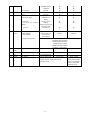
2. Specifications
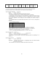
2.1 Basic specifications
No.
1
Print specs.
Specifications
NP-215/225
NP-325
1. Print method
Line thermal dot
Å
Å
432 dots
576 dots
832 dots
2. Total dots / line
NP-415W
3. Dot density
8 dots / mm
Å
Å
4. Print width
54 mm
72 mm
104 mm
5. Print speed (Max.)
*It can be changed by the
condition.
85 mm / s
70 mm / s
70 mm / s
1 partition drive
1 partition drive
Automatic partition
(ASCII print)
(ASCII print)
drive (ASCII 38 print)
6. Print digits
Font A (12
24)
Font B (9 17)
7. Line feed pitch
2
Character
specs.
36 digits (Font A)
48 digits (Font A)
69 digits (Font A)
48 digits (Font B)
64 digits (Font B)
92 digits (Font B)
0.125 mm
Å
Å
Å
Å
Å
Å
Å
Å
Å
Å
Å
Å
Å
Å
Å
Å
Å
Å
Å
Å
Å
Å
Å
Å
Å
Å
Å
Å
Å
Å
Å
Å
Å
Å
Å
Å
Å
Å
Å
Å
Å
Å
Å
Å
Å
Å
Å
Å
Å
Å
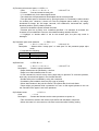
1. Character size
Font A (12
Font B (9
24)
17)
1.50
3.00 mm
1.13
2.13 mm
2. Character types
ASCII
Block graphics
International
3. Character modification
224
80 2
32
Double width
Vertical double
Quadruple
Bold
Double strike
Inverted
90°clockwise rotation
Black/white reverse
Underline
4. Line spacing (Default)
3
Print mode
4.25 mm (1/6 inch)
ANK mode
Bit image mode
Barcode mode
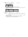
4
Barcode
specs
1-D symbology
UPC-A
UPC-E
EAN-13 (JAN-13)
EAN-8 (JAN-8)
CODE39
ITF
2
CODABAR (NW-7)
CODE128
2-D symology
5
Interface
6
Auto-cutter
Parallel
Serial
1. Cut method
QR code
Centronics
RS-232C
Guillotine type
2. Applicable paper
Thermal 65 - 125
3. Cut cycle
30 cuts / minute
Å
Å
Å
Å
Å
Å
Å
Å
Å
Å
Å
Å
Å
Å
Å
Å
Å
Å
Å
Å
(micro)
4. Cut mode (by command
setting)
Total cut
Partial cut (a 2mm tab
left at the center)
5. Life time
7
Paper
1. Paper width
specs.
2. Max. diameter
3. Core diameter
300,000 cuts
60 mm
80 mm
112mm
Ø80 mm / Ø83 mm
Ø83 mm
Ø83 mm
Inner Ø12mm
Outer Ø18mm
4. Papers recommended
TF50KS-E2D (Nihon Seishi)
PD160R-N (Shin Oji Seishi)
AFP235 (Mitsubishi Seishi)
TL69KS-R2 (Nihon Seishi)
TL69KS-HW74 (Nihon Seishi)
TC98KS-T1 (Nihon Seishi)
8
Receiving
Approx. 10K bytes
buffer
9
Operation
ALMLED OUT
SW
10
Weight
11
Low sensor
Line feed SW input
Net weight
approx. 550g / 650g
approx. 750g
Approx. 22.5 Ø (approx.2.5m+-1m. When inner
of paper core is Ø 12 and outer is Ø 18)
Reflection sensor.
approx. 1,250g
Approx. 3m +- 1.5m
(When inner of paper
core is Ø 12 and outer
is Ø 18.) Changeable
reflection sensor
3
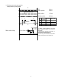
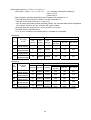
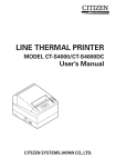
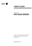
2.2 Printing area and cutter position
Cutter position (Cutting place)
A
TOP
Cutter position
0.0mm
3.0mm
Head position
17.5mm
Sensor position
28.5mm
Unprintable area
1
2
D
0.125mm
B
C
B
9.1+-0.5mm
Black mark printing
A
B
C
D
NP-215
NP-225
60mm
3mm
54mm
432dot
NP-325 NP-415W
80mm
4mm
72mm
576dot
112mm
4mm
104mm
832dot
1. Black mark printing is used
when preprint paper is formatted
5.3+-0.2mm min.
and used.
2. Black mark printing is printed on
10.3+-0.2 mm min. the backside with black ink.
3. Do not print around the black
mark printing area with dark ink.
4
2.3 Power supply specifications
1) Power voltage
2) Current consumption *2, *3
: DC24V 5%
NP-215/225
1 partition 2 partition
Standby
ASCII printing
(Printing average of 16%)
Bit image printing
(Max 100%)
Approx.
1.4A
Approx.
6.0A
NP-325
1 partition 2 partition
Approx. 0.1A
Approx.
Approx.
1.7A
1.1A
Approx.
Approx.
7.8A
4.1A
Approx.
0.9A
Approx.
3.2A
NP415W
1 partition 2 partition
-
Approx.
1.3A
Approx.
5.7A
*2: A sufficient volume of power supply is required to maintain print quality due to high peak current
that may run according to printing.
*3: If power supply cable is excessively long, the operation may become unstable. Cable should be
made as short as possible. If not available, connect cables near the printer and place an electrolysis
condenser of 2200 between power supply and ground. Voltage resistance should be higher than
35V.
* For preventing from static electric discharge, make sure to connect FG wire.
2.4 Reliability
1) Head life
: Average resistance change rate to head less than 15%, except
defects caused by dust or others
Pulse
: More than 100 million pulses (with recommended paper)
Wear distance
: More than 50 km (with recommended paper)
2) Operation environment : Temperature 0 – 45
Print guarantee 5 - 40 , no condensation
3) Storage environment
: Temperature -20 - 60
* When storing for a long time, paper must be kept loaded between head and platen.
4) Frame Ground (FG) wire
The FG wire (Green and Yellow) is coming from the printer body. Make sure to ground the wire
near the body frame when installing the printer. FG grounding is effective for minimizing the noise
level, preventing from SED and maintaining the FG safety for head, cutter, body frame, power
supply and Data connectors.
5) Safety regulation
CE marking
UL60950
6) EMC
EMI: EN55022
VCCI: Class A
FCC: Class A
EMS: EN55024
5
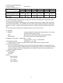
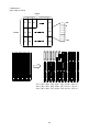
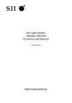
2.5 Dimensions
1) NP-215 dimensional drawing
This drawing is for NP-215P.
6
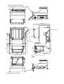
2) NP-225 dimensional drawing
This drawing is for NP-225P.
7
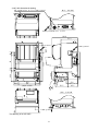
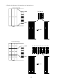
3) NP-325 dimensional drawing
This drawing is for NP-325P.
8
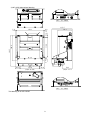
4) NP-415W dimensional drawing
This drawing is for NP-415WP.
9
3. Interface specifications
3.1 Parallel interface (Centronics)
1) Data input
: 8 bit parallel method(DATA 0 – DATA 7)
2) Control signals
: /ACK, BUSY, /STB, /ERROR, PE, SLCT, /INIT
3) Input signal to a printer
DATA 0 – 7
: 8 bit parallel signal(positive logic)
/STB
: Signal to read 8 bit data(negative logic)
/INIT
: Signal to reset an entire printer(negative logic)
/LF
: Signal to feed paper to print mechanism(negative logic)
4) Output signal from a printer
/ACK
: Enquiry signal for 8 bit data. It’s also pulse signal which is output after
BUSY signals (negative logic)
BUSY
: Indicate BUSY status of the printer. Inputs new data at LOW status
(positive logic)
/ERROR
: This signal becomes LOW when a printer is in the alarm status.
In the LOW status, all control circuits in the printer stops (negative logic)
PE
: Outputs when roll paper becomes empty (positive logic)
SLCT
: Signal to indicate on-line status (positive logic)
5) Input/Output signal level
Standard value
Code
Unit
Min.
TYP.
Max.
Input low level
VIL
0.18Vcc
V
Input high level
VIH
0.7Vcc
V
Output low level
VOL
0.7Vcc
V
Output high level
VOH
0.7Vcc
V
*IOL4mA
6) Input/Output conditions
3.3K
VCC
100
470p
74LV14
VCC
STROB
IN PUT
10K
3.3K
VCC
74LV574
3.3k
PD0~PD7
IN PUT
510
INIT IN
1SS319
47
74LV14
ACK, P E, SLCT, ERROR
OUT PUT
47
74LV32
IN PUT
BUSY
OUT PUT
10
LF
IN PUT
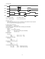
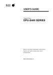
7) Timing chart
POWER
T2 T3
DATA
/STB
BUSY
T1
T4
T5
T6
/ACK
T1 = 3500msec (Max)
T2, T3 = 500nsec (Min)
T4 = 500nsec (Max)
T5, T6 = 4microsec(TYP)
8) Receive control
When BUSY signal stays at LOW, it is feasible to receive data from host computer.
But not feasible when BUSY signal stays at HIGH.
3.2 Serial interface (RS-232C)
1) Synchronization
: Asynchronous
2) Transmission speed: 4800, 9600, 19200, 38400bps (user selectable)
3) A word consists of
Start bit
: 1bit
Data bit : 7 or 8 bit (user selectable)
Parity bit
: odd, even or no parity (user selectable)
Stop bit
: more than 1 bit
4) Signal polarity
RS-232C
Mark
=
Logic “1” (-3V -- -12V)
Space =
Logic “0” (+3V -- +12V)
5) Receive data (RD signal)
RS-232C
Mark
=
1
Space =
0
6) Reception control (DTR signal)
RS-232C
Mark
=
1
Space =
0
7) Transmission control (TD signal)
DC1, [11]h
XON:
Enable data receiving
DC3, [13]h
XOFF: Disable data receiving
11
3.3 Connector connections
1) J1
Power input
2) CN2 Connect to printer mechanism (head)
3) CN3 Connect to printer mechanism (motor)
4) CN4 Connect to printer mechanism (sensors)
5) CN5 Data signal input
6) CN6 Connect to autocutter
7) CN7 Connect to auxiliary sensor(paper low end)
8) CN8 Connect to operation panel
9) CN9 Connect to presenter (NPT-301 only)
3.4 Connector signal details
1.J1 power input connecter (D type)
Printer side connector
: B4B-XHA (JST)
Mating connector : XHP-4 (JST)
Pin #
Signal name
Input/Output
Function
1
VH
Input
Power DC +24V
2
VH
Input
Power DC +24V
3
GND
Power GND
4
GND
Power GND
* A sufficient volume of power supply is required to maintain print quality due to high peak
current that may run according to printing. If power supply cable is excessively long, the
operation may become unstable. Cable should be as short as possible. If not available,
connect cables near the printer and place an electrolysis condenser of 2200
between
power supply and ground. Voltage resistance should be higher than 35V. Make sure to
connect FG wire to prevent from ESD problems.
2. Power input connecter (P type, R type)
Printer side connector
: TCS7960-532010 (Hoshiden)
Mating connector : TCP8927-53-1100, TCP8935-53-1100 (Hoshiden) Equivalent
Pin #
Signal name
Input/Output
Function
1
VH
Input
Power DC +24V
2
GND
Power ground
3
Not available
Shell
FG
FG
* A sufficient volume of power supply is required to maintain print quality due to high peak
current that may run according to printing. If power supply cable is excessively long, the
operation may become unstable. Cable should be as short as possible. If not available,
connect cables near the printer and place an electrolysis condenser of 2200 between
power supply and ground. Voltage resistance should be higher than 35V. Make sure to
connect FG wire to prevent from ESD problems.
12
3. Data signal input connecter (Parallel)
Printer side connecter: 57-40360 (DDK) equivalent
Mating connecter: 57F-40360-20N (DDK) equivalent
Pin#
Signal
In/Output
Function
1
/STB
Input
Data read assign signal
2
PD0
Input
Parallel print data 0
3
PD1
Input
Parallel print data 1
4
PD2
Input
Parallel print data 2
5
PD3
Input
Parallel print data 3
6
PD4
Input
Parallel print data 4
7
PD5
Input
Parallel print data 5
8
PD6
Input
Parallel print data 6
9
PD7
Input
Parallel print data 7
10
/ACK
Output
Data processing end signal
11
BUSY
Output
Receive data not ready signal
12
PE
Output
No paper signal
13
SLCT
Output
Connection select signal
14
Not fixed
*
19
GND
Common ground
31
/INIT
Input
Initialize signal
32
/ERROR
Output
Control stop signal
36
Not fixed
*
15-18
20-30
Not fixed
35
* 14 and 36 are kept as “HIGH”. Do not connect them.
4. Data signal input connecter (Serial)
Printer side connecter: JEC-9S (JST) equivalent
Mating connecter: JEC-9P (JST) equivalent
Pin#
Signal
In/Output
Function
2
RXD
Output
Serial receive data
3
TXD
Input
Serial transmit data
4
DTR
Output
Data transmit permit signal
5
GND
GND for signal
6
CTS
Input
Transmit permit signal
7
DTR
Output
Data transmit permit signal
8
CTS
Input
Transmit permit signal
1, 9
N.C
-
13
Remarks
For extension
For extension
Remarks
Connect to No.7
Connect to No.8
Connect to No.4
Connect to No.6
5. Data signal input connecter (Parallel/Serial)
Printer side connecter: XG4C-2631 (Omron) equivalent
Corresponding housing: XG4M-2630-T (Omron) equivalent
Pin#
Signal
In/Output
Interface
Function
Remarks
1
/STB
Input
Parallel
Data read assign signal
2
PD0
Input
Parallel
Parallel print data 0
3
PD1
Input
Parallel
Parallel print data 1
4
PD2
Input
Parallel
Parallel print data 2
5
PD3
Input
Parallel
Parallel print data 3
6
PD4
Input
Parallel
Parallel print data 4
7
PD5
Input
Parallel
Parallel print data 5
8
PD6
Input
Parallel
Parallel print data 6
9
PD7
Input
Parallel
Parallel print data 7
10
/ACK
Output
Parallel
Data processing end signal
11
BUSY
Output
Parallel
Receive data not ready signal
12
PE
Output
Para/Ser. No paper signal
13
SLCT
Output
Parallel
Connection select signal
14
Not fixed
*
For extension
15
/ERROR
Output
Para/Ser. Control stop signal
16
/INIT
Input
Para/Ser. Initialize signal
17
Not fixed
*
For extension
18,19
GND
Para/Ser. Ground for signal
20
/LF
Input
Para/Ser. Paper feed signal
21
TXD
Output
Serial
Transmit data
22
RXD
Input
Serial
Receive data
23
CTS
Input
Serial
Transmit permit signal
24
DTR
Output
Serial
Data transmit permit signal
25
GND
Para/Ser. Signal ground
26
VH
Input
Para/Ser. DC +24V
z Connect GND and DC+24V to stabilize circuit. Since 14 and 17 are kept as
“HIGH”, do not connect them.
6. CN6 Autocutter sensor (control switch), motor
Printer side connector : 5483-04AX (Molex)
Mating connector : 5480-04 (Molex)
Pin #
Signals
Input/output
Functions
1
M+
Output
Motor drive signal
2
MOutput
Motor drive signal
3
CSW1
Input
HP detect SW output
4
CSW2
HP detect SW GND
7. CN7
Auxiliary sensor (paper near end sensor)
Printer side connector: 53047-0310(Molex)
Mating connector: 51021-0300(Molex)
Pin# Signal name
In/Output
Functions
1
LED+
Output
Anode of LED
2
PNE
Input
Collector of
phototransistor
3
SG
Signal ground
Remarks
At High
Paper out
Cathode or emitter
connect
4
SG
Signal ground
* Valid when DIP SW S2-7 is on.
* When PNE signal is “High”, PE signal of CN5 outputs. Printing operation is not affected.
14
1)
2)
3)
4)
8. CN8 Connect to operation panel
Printer side connector: 53047-0310(Molex)
Mating connector 51021-0300(Molex)
Pin# Signal name
In/Output
Functions
Remarks
1
/LF
Input
Paper feed signal input
Active at L
2
ALM
Output
Printer error signal
Output in
Output
printer error
3
SG
Signal ground
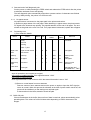
Paper feed is executed according to the paper feed pitch set by ESC 2, ESC 3. However, if
there is no paper, line feed is not executed.
While paper feed signal is at “L”, set Power on to activate self-diagnostic printing.
While paper feed signal is at “L”, release INIT signal to “H” to activate diagnostic printing.
ALM signal (for operation panel) indicates printer statuses as follows:
A protective resistance is incorporated on the board, a light diode can be located between
2 and 3. 2: anode and cathode.
Display pattern
1
0
1
0
Printer status
Normal status
Print (receive) ready
How to solve the problem
No paper
Head up status
F/W write mode
Load the paper
Set head down
Set the power on again
1
Presenter in cramp status
Head temp high (80˚c)
0
1
0
Wrong head connection
Auto-cutter error
Presenter error
Pull out the clamped paper
Printer returns normal at head temp of
60˚c
Connect head cable properly
Remove jammed paper and turn
power on again, or input INIT signal
1
0
9. CN9 Connect to presenter (NPT-301 only)
Printer side connector: 53047-0810
Mating connector: 51021-0800
Pin #
Signal
Input/output
Remarks
6
LED +
Output
To sensor LED1
7
Sensor 1
Input
From sensor 1
8
SG
Signal GND
9
LED2 +
Output
To sensor LED2
10
Sensor2
Input
From sensor2
11
SG
Signal GND
12
M+
Output
Motor drive output
13
MOutput
Motor drive output
* Connect to NPT-301 only. When connect to other product, it would cause problems.
15
4. Functions
4.1 Function setting
4.1.1 DIP switch S1
Function
ON
OFF
S1-1 Interface
Serial
Parallel
S1-2 Select emulation
Windows
ESC/POS
S1-3 Select fixed division
2 partition
1 partition
S1-4
Refer to the following
Baud rate
table
S1-5
S1-6 Parity check
Yes
No
S1-7 Parity bit
Odd
Even
S1-8 Data bit
7 bit
8 bit
Baud rate
4,800bps 9,600bps 19,200bps 38,400bps
S1-4
OFF
OFF
ON
ON
S1-5
OFF
ON
OFF
ON
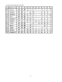
4.1.2 DIP switch S2
Function
ON
OFF
Factory setting
**5P
**5R
**5D
OFF
ON
OFF
OFF
OFF
OFF
OFF
OFF
OFF
OFF
OFF
OFF
OFF
OFF
OFF
OFF
OFF
OFF
OFF
OFF
OFF
OFF
OFF
OFF
Factory setting
**5P
**5R
ON
ON
OFF
OFF
OFF
OFF
OFF
OFF
OFF
OFF
OFF
OFF
ON
ON
OFF
OFF
**5D
ON
OFF
OFF
OFF
OFF
OFF
ON
OFF
S2-1 Auto cutter
Yes
No
S2-2 Character set
Overseas
Japanese
S2-3 Serial control (DTR)
XON/XOFF
DTR/DSR
S2-4
Japanese settings
S2-5 Presenter
Yes
No
S2-6 Flash ROM
Rewrite
No
S2-7 Paper low end
Yes
No
S2-8 Print density
Thick
Standard
Note:
1. S2-1 OFF (autocutter OFF) will be in winder drive setting (current consumption
should be less than 200mA). If autocutter is connected, the autocutter activates
and paper is cut off. It may cause paper jam.
2. For writing ROM, set the DIP switches as stated below and turn the power on
after changing CN8 NO.1 pin LF to “L” position or while pressing the paper feed switch on
the operation panel. After the operation, set the power off.
3. Rewriting Flash ROM boot program: S2-6 ON and S2-2 OFF.
4. Rewriting Flash ROM F/W: S2-6 ON and S2-2 OFF.
5. Use S2-6 in OFF position. If set ON to use, the program may be destroyed.
6. For NP-215, S2-7 (factory setting for “near end”) should be set OFF.
7. For NP-415W, S1-2 (factory setting for emulation) should be set ON.
4.1.3 Self diagnostic print
1. By performing self-diagnostic print following items are checked.
a) Proper function of control circuitry
b) Proper function of printer mechanism
c) Print quality
d) Control F/W version
e) DIP switch setting status
f) Correct function of paper out sensor
g) Head wide and head rank (automatically detected)
16
2. Start and end of self diagnostic print
Set the power on while pressing the FEED switch and release the FEED switch after the printer
mechanism activates to start self-printing.
The self diagnostic print automatically ends when a preset number of characters are finished
printing. While printing, the printer is in Off-line mode.
4.1.4 No paper sensor
No paper sensor is mounted on the paper path in the printer mechanism.
It detects no paper status of the roll paper. When detecting no paper status, the printer sends
PE signal to the host and stop printing. Pay special attention to the end of roll paper. The end
should not be glued to the core of the roll. If no paper status is detected, replace the roll paper.
4.2
Processing error
1) Error detection details
Name
Comm. error
Status
232C Comm. error
Parity
Overrun
Flaming
BUSY
PE
-
-
/ERROR 232C
status
-
PL
status
-
Removal
Align comm.
condition
Data “?” print
Paper near
end
Paper remain sense
CN7 sensor
L
H
H
Obit 1
-
Load paper
Head up
Head up
L
L
L
1bit 1
On
Paper end
No paper
L
H
L
2bit 1
On
Head up lever
down
Load paper
Head temp
high
Over 80°C
L
L
L
3bit 1
Flash
Cutter error
Cutter jam
Return normal
with 60°C
Remove jam and
POWER OFF , /INIT
When the above errors are detected except transmission error and paper low end error, printer
stops all operations and outputs error signal.
In the case of parallel interface: Error signal becomes “LOW”
In the case of serial interface:
Error signal becomes “LOW” and error bit in the status information is set to “ON”.
2) Return to normal status from error statuses
Remove causes of error statuses and turn the power on again or input the /INIT signal to
return to normal. When this process is activated, at the time of power switch turned off, the
printer will be initialized, so that settings are required again.
If data remains in the buffer, attention should be paid
4.3 Buffer full print
If there remains data in the buffer after one line of data is received, printer automatically prints
preceding data. The volume of buffer full data varies depending on ASCII characters or bit
images.
17
4.4 Automatic paper cut
“Automatic paper cut” after paper is manually fed by pressing FEED button.
If manual line feed is conducted for more than 10 lines, the paper is automatically cut off after
the paper feed is finished. This function is not available when the line feed is conducted by
control command.
4.5 Winder drive
When no autocutter is mounted, autocutter drive motor functions as external rewinder drive.
CN6
Autocutter sensor (control switch), Outputs to motor pins 1 and 2
S2-1
OFF: rewinder drive
ON: autocutter drive
DC motor with DC 24V, approx. 200mA
In about 1 to 2 sec. rewinder output is turned OFF after printing and paper
feed.
If overloaded with higher current than specified and the status continues,
the ICs may be damaged.
4.6 Partition drive
The fixed drive (1 or 2 partition drives) or “automatic partition drive” can be selected by the DIP
switch and commands. It should be selected according to the power supply and print duty.
1) Fixed partition
Function
ON
OFF
S1-3 Fixed partition select
2 partitions
1 partition
1) NP-415W is assigned to 2 fixed partitions.
2) 2 fixed partition select may decrease print speed.
3) 2 fixed partition select may decrease print quality.
2) Automatic partition drive
1 partition
2 partitions
NP-215/225 Less than 215 dots
Higher than 216 dots
NP-325
Less than 287 dots
Higher than 288 dots
NP-415W
Less than 415 dots
Higher than 416 dots
1. Automatic partition drive select will automatically change the print speed according to
print ratio. Print noise may appear.
2. The default value selected by commands will be the fixed partition selected by. The
DIP switch. Refer to the section 5.3.
3. Automatic partition select may decrease print quality.
18
5. Control commands
5.1 Control command table
Control codes
Functions
Pages
1
HT
Horizontal tab
20
2
CR
Carriage return
20
3
LF
Print and line feed
20
4
FF
Page feed
20
5
ESC C n
Page length set for n lines
20
6
ESC SP n
Character right space set
20
7
ESC ! n
Print mode overall set
21
8
ESC % n
Down load character set/reset
21
9
ESC & s n m a Dn
Down load character definition
21
*10
ESC * m n1 n2 Dn
Bit image mode set
24
11
ESC – n
Underline set/rest
26
12
ESC 2
1/6 inches line feed set
26
13
ESC 3 n
Smallest line feed pitch set
26
14
ESC @
Initialize printer
26
15
ESC D n1 n2 --- NUL
Set horizontal tab position
26
16
ESC E n
Bold print set/reset
27
17
ESC G n
Double strike print set/reset
27
18
ESC J n
Print and smallest pitch line feed
27
19
ESC R n
Select international character
27
20
ESC c 5 n
Feed switch enable/disable
28
21
ESC d n
Print and n line feed
28
22
ESC t n
Select character code table
28
23
ESC v
Send printer status
28
24
ESC { n
Inverted character set/reset
29
25
ESC V n
29
Character 90° clockwise rotation set/reset
*26
ESC $ n1 n2
Absolute position set
29
27
ESC \ n1 n2
Relative position set
29
28
GS k n Dn NUL
Barcode print
30
29
GS w n
Barcode width select
30
30
GS h n
Barcode height select
30
31
GS H n
HRI character print position select
30
32
GS f n
HRI character style select
30
33
GS * n1 n2 Dn
Download bit image define
31
34
GS / m
Download bit image print
31
35
GS :
Macro definition start/end
32
36
GS ^ n1 n2 n3
Macro define
32
37
ESC = n
Data input control
32
38
ESC a n
Position align
33
*39
ESC i
Full cut
33
*40
ESC m
Partial cut
33
41
ESC c 3 n1 n2
No paper signal sensor select
33
42
ESC r n
Compulsory eject
34
43
ESC q S E M
QR code print
34
44
GS T n
Register NV bit image
36
45
GS P n
Print NV bit image
36
46
GS d Dn
Download firmware
36
47
GS B n
Black/white reverse print set/reset
37
48
ESC h n
Presenter eject mode select
37
49
ESC B n
Back feed
37
50
DC1
Reset software
37
51
GS % n
Partition drive select
38
52
GS ~ n
Print density set
38
* Functions differently between printer with standard type driver and Windows type.
19
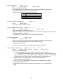
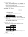
5.2 Printer driver
Please apply the driver stated below for using under Windows environment. Please refer to the
User’s Manual for a driver.
1) Windows 95/98: NII printer driver Windows 95/98, Version 1.00
2) Windows NT4.0: NII printer driver Windows NT4.0, Version 1.00
3) Windows 2000: NII printer driver Windows 2000, Version 1.00
5.3 Control command details
1) Horizontal tab
: <<HT>>
Code
: [09] h
Shift the print position to the next horizontal tab position
* Horizontal tab position is set by [horizontal tab set] command.
* The default of horizontal tab position is every 8th character (9th digit,
17th digit, 25th digit and 33rd digit) in font A.
* Maximum digit position for NP272 is 33rd and for NP-372 is 41st.
* If the next tab position is not set, this command is ignored.
2) Carriage return: <<CR>>
Code
: [0D] h
This command is ignored.
3) Line feed
: <<LF>>
Code
: [0A] h
Prints data stored in the input buffer and executes line feed according to data
of feed pitch.
4) Page feed
: <<FF>>
This command is effective only in Windows mode.
Code
: [0C] h
* Prints data in the print line buffer and executes page feed to the head of next page
according to the page length in the setting.
* Default setting for the page length is 66 lines.
5) “n” line page length setting: <<ESC C n>>
Code
: [1B] h + [43] h +n
* [01≤n≤FF] h
Sets a page length for “n” lines with current line feed pitch.
* Position is set to the head of page
* Line pitch change after setting will not change page length.
* Default value for “n” is [42] h for 66 lines.
* If printer is initialized, the head of page is also initialized.
6) Setting right space of a character: <<ESC SP n>>
Code
: [1B] h + [20] h + n
* [00≤n≤20] h
Sets the right space of a character by unit of dot (1/203 of an inch). In the case of
double width mode, the space will be doubled. The default value of “n” is [00] h.
20
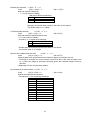
7) Overall print mode setting: <<ESC ! n>>
Code
: [1B] h + [21] h + n
Sets print mode. “n” has following meanings
Bit
* [00≤n≤FF] h
Values
Function
0
1
0
Character font
Font A
Font B
1
Undefined
2
Undefined
3
Bold
Reset
Set
4
Double height
Reset
Set
5
Double width
Reset
Set
6
Undefined
7
Underline
Reset
Set
* If double height and double width are set at the same time quadruple character will be formed.
* All of the printed characters will be underlined except for the 90° rotated characters and spaces
created by horizontal tab.
* Underline width is determined by the value set in [Underline set/reset] section.
The default value is “1”.
* Different sizes of character mixed such as double width and normal size can be printed.
* The default value of “n” is [00]h.
8) Down load characters set/reset : <<ESC % n>>
Code
: [1B] h + [25] h + n
* [00≤n≤FF]h
Setting or resetting the characters to be downloaded.
* Unable to use download character set & download bit image set at the same time.
* Only LSB (b0) is valid for “n” value. LSB (b0) has the following meanings.
b0
Function
0 Resets download chraracter
1 Sets download chraracter
Default value is “n” = [00]h
9) Definition of download character:<< ESC & s n m a Dn>>
Code
: [1B ] h + [26] h + s + n + m + a + Dn
* [s = 03 ] h
* [20≤n≤7E ] h
* [20≤m≤7E ] h
* font A [ 00≤a≤0C ] h
* font B [ 00≤a≤09] h
Definition of download character( such as alpha numeric).
1. “s” indicates a number of bytes in a vertical direction and “a” is a number of dots in
horizontal direction.
2. “n” indicates the start character code, and “m” means the end character code. If only 1
character should be defined, then n = m.
3. Definable characters are from <20>h to <7E>h in ASCII code (95 characters).
4. “Dn” indicates the data to be defined. It indicates the “a” dots pattern from the left.
Remaining area on the right of a character is filled with spaces.
5. Once a download character is defined, it remains valid until the download character is
redefined, printer is initialized, reset signal is input, or the power is turned off.
6. Only area specified will be reset.
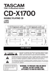
21
< Reference >
In the case of Font A
12dots
24dots
P1
P4
P2
P5
P3
P6
P7
P34
MS
B
P35
P36
LSB
P1= 00 h,P4= 00 h,P7= 00 h,P10= 00 h,
P2= 00 h,P5= 00 h,P8= 0F h,P11= 72 h,
P3= 08 h,P6= F8 h,P9= 08 h,P12= 00 h,
22
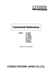
< Reference >
In the case of Font B
9dots
P1
P4
P2
P5
P3
P6
MSB
P25
17dots
P26
LSB
MSB
P27
LSB
P1= 40 h,P4= 7F h,P7= 41 h,P10= 41 h,
P2= 04 h,P5= FC h,P8= 04 h,P11= 04 h,
P3= 00 h,P6= 00 h,P9= 00 h,P12= 00 h,
23
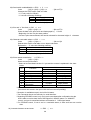
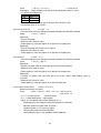
10) Bit image mode set: << ESC * m n1 n2 Dn >>
Code: [1B] h + [2A] h + m + n1 + n2 + Dn
* [m = bit image mode(refer to below)] h
* [00≤n1≤FF] h
* [00≤n2≤02] h
Data is printed in bit image by following the bit image mode specified by “m”.
* Print total dots divided by 256, quotient is n2 and remainder is n1.
* Total dots in bit image mode are n1 + (256 x n2).
* If the bit image input data exceeds specified position, the exceeded data will be disregarded.
NP-215/225: 432 dots. NP-325: 576 dots. NP-415W: 832dots.
* Bit image data (Dn) interprets bit 1 as print and bit 0 as not print.
* Bit image mode is indicated below.
* If “m” is out of conditions set, the data after n1 is treated as normal data.
[Standard]
Vertical direction
m
(hex)
00
01
20
21
Bit image
mode
8 dots
single density
8 dots
double density
24 dots
single density
24 dots
double density
Horizontal direction
Maximum dot number
NP-215
NP-325
NP-415W
NP-225
Dot
quantiy
Dot
density
Dot
density
8
67DPI
101DPI
216
288
416
8
67DPI
203DPI
432
576
832
24
203DPI
101DPI
216
288
416
24
203DPI
203DPI
432
576
832
[Windows]
Vertical direction
m
(hex)
Bit image
mode
Dot
quantiy
Dot
density
Dot
density
Horizontal direction
Maximum dot number
NP-215
NP-325
NP-415W
NP-225
24 dots
24
203DPI
67DPI
144
192
277
single density
24 dots
21
24
203DPI 101DPI
216
288
416
double density
24 dots
22
24
203DPI 135DPI
288
384
554
single density
24 dots
23
24
203DPI 203DPI
432
576
832
double density
24 dots
203DPI
432
832
832
24
24
203DPI
double density
(406DPI)
(864)
(1664)
(1664)
* The data for [Windows] m = 24h is equivalent to m=23h due to the mechanical specification.
20
24
< Relationship between bit image data and printed dots >
8 dots bit image
MSB
D1
D2
D1 D2 D3
D3
LSB
=1dot
24 dots bit image
D1
D4
D7
D2
D5
D8
D3
D6
D9
MSB
D1 D2 D3 D4 D5 D6 D7 D8 D9
LSB
=1dot
25
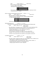
11) Underline set/reset
: <<ESC - n>>
Code
: [1B] h + [2D] h + n
* [00≤ n ≤02 ]h
Sets and resets the underline
* Underline is valid for all characters except for the area skipped by horizontal tab.
* Also Underline is not valid for 90° rotated character.
* Underline is verified with n value as shown bellow.
n(hex)
Type of underlines
00
Reset underline
01
Set one dot underline
02
Set two dot underline
Default value is “n” = [00]h
12) 1/6th of an inch line feed pitch
: << ESC 2>>
Code
: [1B ] h + [32] h
Sets one line feed to 1/6th of an inch.
13) Sets smallest pitch line feed : << ESC 3 n >>
Code
: [1B ] h + [33 ] h + n
* [00≤ n ≤FF] h
Sets a line feed pitch to n/203rd of an inch.
* Despite of height set by value, the same space with character height is sent by line feed.
* The default value of n is [22]h
* If n=[00]h is set, printer will not feed by pressing FEED button.
14) Printer initialization
: << ESC @ >>
Code
: [1B ] h + [ 40 ] h
Clears the data stored in the print buffer and resets each setting to default values.
* It does not clear the data stored in the internal receive buffer.
* Rewrites the DIP switchs.
* It is stored in the internal receive buffer and activated in sequential.
15) Horizontal tab position set
: << ESC D n1 n2 --- NUL >>
Code
: [1B ] h + [44] h + n1+ n2+ --- + [00 ] h
*[00≤ n ≤FF ] h
Sets the horizontal tab position
1. “n” indicates the digits number from the left. In this case, n = tab position - 1.
2. Tab position is set at the location of character width x n from the beginning of a
line. The character width in this case includes character right space. When double
width function is set, then the width becomes double of ordinary character.
3. Maximum number of tab positions is 32. If setting exceeds 32, then
the exceeded values are neglected.
4. < ESC D NUL > clears all tab positions being set. After the tab is cleared,
horizontal tab will be ignored.
5. Default value is set at every 8 characters of font A (at 9 th, 17th, 25th and 33rd
digit).
26
16) Bold print set/reset :<< ESC E n >>
Code
: [1B] h + [45] h + n
* [00≤ n ≤FF] h
Sets and resets the bold print
* “n” is only valid for LSB(b0)
LSB (b0) is defined as following.
b0
Values
0
Resets bold print
1
Sets the bold print
Valid for all characters
Bold print and double strike results in the same on this printer.
The default value of “n” is [00]h.
17) Double strike set/reset
:<< ESC G n >>
Code
: [1B] h + [47] h + n
* [00≤n≤FF] h
Sets and resets the double strike function
* “n” is only valid for LSB(b0)
* Control by “n” is explained as following.
b0
Description
0
Resets double strike
1
Sets double strike
* Double strike and bold print result in the same on this printer.
* The default value of “n” is [00]h.
18) Print and smallest pitch line feed:
<< ESC J n >>
Code
: [1B ] h + [4A ] h + n
* [00≤n≤FF] h
Prints the data in the print line buffer and feeds the paper by n/203rd of an inch.
* The height of character for a line is always sent by line feed. If the value of height is set
by “n” below the height of character, the same space with character height is sent by
line feed.
* Beginning of a line is a print start position.
19) International character select :<< ESC R n >>
Code
: [1B ] h + [52] h + n
Selects the international characters.
* The values of “n” have following meanings
n(Hex)
Character sets
00
U.S.A.
01
France
02
Germany
03
England
04
Denmark 1
05
Sweden
06
Italy
07
Spain
08
Japan
09
Norway
0A
Denmark 2
Default value of “n” is [08]h.
27
* [00≤n≤0A] h
20) Panel switch enable/disable:<< ESC c 5 n >>
Code
: [1B ] h + [63] h + [35] h + n
Changes the FEED switch valid or invalid.
* “n” is only valid for LSB(b0)
* “n” bit has a following meanings
b0
Description
0
enable FEED switch
1
disable FEED switch
Default value of “n” is [00]h.
* [00≤n≤FF] h
21) Print and “n” line feed:<< ESC d n >>
Code
: [1B] h + [64] h + n
* [00≤n≤FF] h
Prints the data in the print buffer and feeds paper by “n” lines.
* Beginning of a line is a print start position.
* If there is print data remained, line feed is activated for the same height of
character.
22) Character code table select:<< ESC t n >>
Code
: [1B] h + [74]h + n
* [00≤n≤01]h
Selects either Japan code table or non-Japan code table.
Explanation : “n” value has following meaning.
n(Hex)
character code table
00
Non-Japan character code table
01
Japan character code table
The default value of “n” is [S2-2] for DIP SW.
23) Printer status transmission :<< ESC v >>
Code
: [1B] h + [76] h
Sends current printer status
* Status to be transmitted consist of 1 byte and the content is explained in the chart
below.
Value
bit
Functions
0
1
0
paper near end
paper present
near end
1
platen open
normal
head open
2
paper end
paper present
no paper
3
head temp. abnormal
normal
Temp. high
4
cutter problem
normal
cutter problem
5
presenter problem
normal
presenter problem
paper remove sensor
6
no paper
paper present
information
7
not defined
* Make sure that command is issued before transmission of print data.
(commands are stored in the input buffer and executed sequentially)
* Reception is available except in the buffer full status.
* The commands above are valid only for serial interface.
* Regarding DTR/DSR control, only one byte is transmitted after confirmation that the
host is able to receive data, that is DSR signal is in SPACE status. For XON/OFF
control, one byte is transmitted without confirmation of DSR signal status.
* For DTR/DSR control, if host is not in a receivable status, it waits until host can receive
data.
24) Inverted character set and reset
:<< ESC { n >>
28
Code
: [1B] h + [7B] h + n
* [00≤n≤FF] h
Sets or resets the inverted character function
* “n2 is only valid for the LSB(b0)
* LSB (b0) has the following meaning
b0
Description
0
resets inverted character
1
sets inverted character
* The command is only valid when it is assigned at the beginning of a line.
* The default value of n is [00]h.
25) 90° clockwise rotated character set and reset :<< ESC V n >>
Code
: [1B] h + [56] h + n
* [00≤n≤01] h
Sets and resets 90° clockwise rotated character.
* Underline cannot be assigned to the 90° clockwise rotated character.
* “n” has the following meaning.
n(hex)
description
00
reset 90° rotated character
01
set 90° rotated character
* Default value for “n” is [00]h.
26) Absolute position set
:<< ESC $ n1 n2>>
*The function of this commands differ between Standard type and Windows type.
Code
:[1B] h + [24] h +n1 +n2
* [00≤n1≤FF] h
* [00≤n2≤02] h
Print start position is assigned by dots in 1/203rd of inch from the beginning of line.
* Divide the value of dot by 256, place quotient to n2, and remainder to n1.
* The print start position is n1 + n2 x 256 from top of the line.
* Setting which exceeds end of line is ignored.
* If the command is received in the middle of line, the action will be:
Standard: the value that does not exceed the current position is ignored.
Windows: the value that does not exceed the current position is also valid.
27) Relative position set
:<< ESC \ n1 n2>>
Code
: [1B] h + [5C] h + n1 +n2
* [00≤n1≤FF] h
* [00≤n2≤02] h
Print start position is assigned by dots from current position in unit of 1/203rd of inch.
* Right direction is treated as plus and left as minus.
* For assigning N dots in minus direction (left), it will be: N dots = 65536 - N
* Divide dots by 256, quotient is n2 and remainder is n1.
* Assigning beyond the end of a line is neglected
29
28) Barcode print
:<< GS k n Dn NUL >>
Code
: < 1D >h + < 6B >h + n + Dn + < 00 >h
* < 00≤n≤07 >h
Description : Selects barcode symbology and prints barcode.
* The next print start position is on the line head
* Select following barcode symbology with “n” value.
* Dn indicates the character code to be printed.
n (Hex)
00
01
02
03
04
05
06
07
Barcode symbology
UPC-A
UPC-E
EAN-13 (JAN-13)
EAN-8 (JAN-8)
CODE 39
ITF
CODABAR
CODE128
* When there is data in the buffer this command is neglected.
* If character code Dn is not a printable character, following data after Dn will be treated
as normal data.
* If the print character numbers are fixed in the barcode symbology the input character
numbers should match to the print character numbers.
* If horizontal data exceed one line, the exceeded data cannot be printed.
29) Barcode width size select :<< GS w n >>
Code
: < 1D >h + < 77 >h + n
Description : Selects width of barcode
* Default value of “n” is [03]h.
30) Barcode height select
:<< GS
Code
: < 1D >h + < 68 >h + n
Description : Selects barcode height
* “n” shows the vertical dot number
* Default value of “n” is 162([A2]h).
* < 02≤n≤04 >h
h n >>
* < 00≤ n ≤FF >h
31) Select of HRI character print position
:<< GS H n >>
Code
: < 1D >h + < 48 > h +n
* < 00≤ n ≤03 >h
Description : Selects the print position of HRI characters in printing barcode.
* “n” has the following meaning.
n (Hex)
Print position
00
No printing
01
Above barcode
02
Below barcode
03
Above and below barcode
* HRI characters are the characters selected by “HRI character style select”.
* Default value of “n” is [00]h.
32) Select of HRI character style
:<<GS f n>>
Code
: <1D>h+<66>h+n
* < 00≤ n ≤01 >h
Description : Selects HRI character style in printing barcode
* “n” has the following meanings:
n (hex)
Style
00
Font A
01
Font B
* Default value of “n” is [00]h.
30
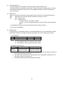
33) Download bit image definition
:<< GS * n1 n2 Dn >>
Code
: < 1D >h + < 2A >h + n1 + n2 + Dn * < 0≤n1≤FF >h
* < 00≤n2≤30 >h
* < n1 x n2≤51F >h
Description : Defines “download bit image” of number of dots specified by n1 and n2.
* Horizontal dot numbers are obtained by n1 x 8 and vertical dot numbers by n2 x 8.
* Dn is bit image data.
* Once “download bit image” is defined, it is valid until it’s redefined, download
character is defined, external characters are specified, software is reset, power is set
off or INIT signal is input.
* “Download bit image” cannot be defined at the same time with “download
characters” or “external characters”. If this command is executed, “download
character definition” or “external characters contents” are cleared.
* The relationship between bit image data & defined dots is shown below.
n1x8dots
d1
MSB
dn2+1
dn2x2+1
d2
dn2+2
dn2x2+2
n2x8dots
LSB
dn2
dn1xn2x8
dn2x2
34) Download bit image print :<< GS / m >>
Code
: < 1D >h + < 2F >h + m
* < 00≤m≤03 >h
Description : Prints “download bit image” in a mode assigned by “m”.
* Modes to be assigned by m are as follows.
Dot density
m
Modes
Vertical Horizontal
00 Normal mode
203 dpi
203 dpi
01 Double width
203 dpi
101 dpi
02 Vertical double
101 dpi
203 dpi
03 Quadruple
101 dpi
101 dpi
* If there are some data left in the print buffer, this command is neglected.
* If “download bit image” is not defined yet, this command is neglected.
* “Download bit image” data exceeding 1 line cannot be printed.
* “Download bit image” cannot be defined at the same time with “download character” or
“external characters”
31
35) Macro definition, start and end
:<< GS : >>
Code
: < 1D >h + < 3A >h
Description : Assigns Macro definition start and end. The size of data defined by Macro
is up to 1,024 bytes. Exceeding to 1,024 byte cannot be defined.
* Defined Macros cannot be cleared by “Printer initialization”. Therefore “printer
initialization” can be included in the Macro definition.
* During the Macro definition, printing can be proceeded.
* Once Macro is defined, the contents become effective until software is reset, power is
set off, or INIT signal is input.
36) Macro execution :<< GS ^ n1 n2 n3 >>
Code
: < 1D >h + < 5E >h + n1 + n2 + n3 * < 0≤n1≤FF >h
* < 00≤n2≤FF >h
* < 00≤n3≤01 >h
Description : Executes Macros being defined
* The definitions of n1, n2 and n3 are:
n1 : times of Macro execution
n2 : wait time of Macro execution
At every execution, there is a wait time of n2 x 100msec.
n3 : Macro execution mode
n3
Mode
00
Consecutive execution
01
Execution by FEED switch
z Consecutive execution: Executes “n1” times with a wait time specified at n2.
z FEED switch execute: After a time specified at n2, waits for PE LED blinks and the FEED
switch depressed. After FEED switch is pressed, it executes Macro once. This action is
repeated by n1 times.
* If the printer receives this command during Macro definition, it stops Macro definition. If
this happened, defined Macros are cleared.
* Nothing happens if Macro is not defined or n1 = 0.
* During Macro execution with n3 = 1, line feed by FEED switch is disabled.
37) Data input control :<< ESC = n >>
Code
: < 1B >h + < 3D >h + n
* < 00≤n≤FF >h
Description:Selects valid device where data input is possible through host computer.
* Each bit of “n” has the following meaning.
Values
Bit
Function
0
1
0
Printer
Invalid
Valid
1
Not defined
2
Not defined
3
Not defined
4
Not defined
5
Not defined
6
Not defined
7
Not defined
* If printer is not in “no selection” status, printer will discard all received data until it is in
the selection status by this command.
* Even if printer is in no selection status, the status may become BUSY by printer
operation.
* The default value of “n” is [01]h.
38) Print position alignment
:<< ESC a n >>
32
Code
: < 1B >h + < 61 >h + n
* < 00≤n≤02 >h
Description : Aligns all data to be printed on the assigned position in a line.
* “n” values are assigned to:
n (Hex)
Position
00
Left
01
Center
02
Right
* This command is valid only when it is input at the head of a line.
* The default value of “n” is [00]h.
39) Total cut (Full cut)
:<< ESC i >>
* The command functions differently between Standard and Windows models.
Code
: < 1B >h + < 69 >h
[Standard]
* Full-cut the paper.
* Effective at the head of a line
* Feeds paper by 3mm after paper cut to prevent from paper jam.
[Windows]
* Full-cut the paper after feeding by 21.25mm
* Effective at the head of a line
* Feeds paper by 3mm after paper cut to prevent from paper jam
40) Partial cut
:<< ESC m >>
* The command functions differently between Standard and Windows models.
Code
: < 1B >h + < 6D >h
[Standard]
* Partially cut paper (with one point left uncut at the center position)
* Effective at the head of a line
* Feeds paper by 3mm after paper cut to prevent from paper jam.
[Windows]
* Partially cut paper (with one point left uncut at the center) after feeding paper by
21.25mm.
* Effective at the head of a line.
* Feeds paper by 3mm after paper cut to prevent paper jam.
41) No paper sensor select
:<<ESC c 3 n1 n2>>
Black mark sensor command
Code
:<1B>h + <63>h + <33>h + n1 + n2 * < 00≤n1≤01 >h
* < 00≤n2≤FF >h
* n1 = 0, no paper sensor
(thermal paper)
* n1 = 1, black mark sensor (label paper)
* Value “n2” is available only at label selection in “n1”.
Feeds paper by dots assigned after label position is confirmed.
Minimum amount of paper feed: 0.125mm
Feeds 0.125mm x “n2” amount of paper
Default value selects the thermal paper.
Auto loading function is not available at label selection.
33
42) Compulsory eject :<<ESC r n>>
Code: <1B>h + <72>h + n
* < 0≤n≤1 >h
* When a ticket or receipt is cramped and it is left untaken for a certain period of time, this
command is used to execute compulsory eject.
* This command rotates a motor either clockwise or counter-clockwise until ticket or
receipt is ejected totally.
n(Hex)
Mode
0
Clockwise
1
Counter clockwise
43) QR code print
:<<ESC q S E M>>
ESC + ”q” + S + E + M + DATA [+ ”,” + M + DATA +……] + NUL
HEX CODE <1B>h + <71>h + S + E + M + DATA [+ <2C>h + M + DATA +….] + <00>h
About parameter
1. S: module size
* Assign 1 module size of QR code by printer’s dot numbers.
* There are 5 sizes which can be assigned, 1, 2, 3, 4, 8 dots
* If invalid size is assigned, the printer assigns it as 4 dots
2. E: Correction level
* Selects error correction level to be used for restoring QR symbol.
* Following values can be assigned.
* If invalid value is assigned, the printer determines it to be L.
E
Correction level
Restore. capability
0
L
7%
1
M
15%
2
Q
25%
3
M
30%
3. M: Input data mode
* Assign input data mode
* Following modes can be assigned
* If invalid mode is assigned, data is ignored until valid
Mode is assigned.
M
Input data mode
“N”
Numeric mode
“A”
Alpha numeric mode
“B”
8 bit byte mode
“K”
Kanji mode
* If multiple modes should be input, each mode data (M + data) needs to be separated by
“ , ”.
* If you want to input “ , ” and NULL in the data of 8 bit byte mode, input “ ! ” <21>h+”,” and
“ ! ”<21> h + NULL.
* “ ! ” itself is input as “ ! ” + ” ! ”
* Kanji data should be input by Shift JIS code.
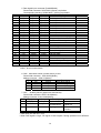
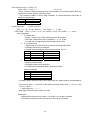
Restrictions
Available QR codes are from version 1 to version 14 of model 1 symbols.
If input data exceeds the area to be printed, QR code is not printed.
34
Following table shows the number of characters and input data capacity for the model 1 in
version 1 to 14.
Correction Data code
Alpha
Version
Data bit Numeric
Byte
Kanji
level
Word
numeric
L
19
148
40
24
17
10
M
16
124
33
20
14
8
1
Q
13
100
25
15
11
6
H
9
68
16
10
7
4
L
36
284
81
49
34
20
M
30
236
66
40
28
17
2
Q
24
188
52
31
22
13
H
16
122
33
20
14
8
L
57
452
131
79
55
33
M
44
348
100
60
42
25
3
Q
36
284
81
49
34
20
H
24
188
52
31
22
13
L
80
636
186
113
78
48
M
60
476
138
84
58
35
4
Q
50
396
114
69
48
29
H
34
268
76
46
32
19
L
108
860
253
154
106
65
M
82
652
191
116
80
49
5
Q
68
540
157
95
66
40
H
46
364
105
63
44
27
L
136
1084
321
194
134
82
M
106
844
249
151
104
64
6
Q
86
684
201
122
84
51
H
58
460
133
81
56
34
L
170
1356
402
244
168
103
M
132
1052
311
188
130
80
7
Q
108
860
253
154
106
65
H
72
572
167
101
70
43
L
208
1660
493
299
206
126
M
160
1276
378
229
158
97
8
Q
128
1020
301
183
126
77
H
87
692
203
123
85
52
L
246
1964
585
354
244
150
M
186
1484
441
267
184
113
9
Q
156
1244
369
223
154
94
H
102
812
239
145
100
61
L
290
2316
690
418
287
177
M
222
1772
526
319
219
135
10
Q
183
1460
433
262
180
111
H
124
988
291
176
121
74
L
336
2684
800
485
333
205
M
256
2044
608
368
253
156
11
Q
208
1660
493
299
205
126
H
145
1156
342
207
142
87
L
384
3068
915
555
381
234
M
292
2332
694
421
289
178
12
Q
244
1948
576
351
241
148
H
165
1316
390
236
162
100
L
432
3452
1030
624
429
264
M
332
2652
790
479
329
202
13
Q
276
2204
656
398
273
168
H
192
1532
454
275
189
116
35
14
L
M
Q
H
489
368
310
210
3908
2940
2476
1676
1167
877
738
498
707
531
447
302
486
365
307
207
299
225
189
127
1. The first code word is 4 bit length, and following all code words consist of 8 bit length.
2. Data bit numbers include “mode indicator” and “character number indicators”.
44) NV bit image registration :<<GS T n>>
Code
: <1D>h + <54>h + n
Description : Register the predetermined bit image print data.
* It is possible to register from 0 to 2 different kinds of patterns (3 patterns).
* In each pattern, up to the maximum of 15cm length (for 2” model) of bit image print data
can be registered; up to the maximum of 11cm for 3” model and up to 7cm for 4” model
can also be registered. The bit image print data exceeding the maximum length is
neglected.
* The registered data is not erased when the power is set on or off or the printer is
initialized.
* “n” has a following meanings.
n (hex)
Function
00
Start of pattern 0 registration
01
Start of pattern 1 registration
02
Start of pattern 2 registration
FF
End of registration
* When registrations started in the middle of a line, whole line is registered.
* When registration ended in the middle of a line, whole line is not registered.
* Following is a command sequence of pattern 0 registration.
GS T 0h + (bit image data assigned by ESC *) x n lines + GS T FFh
45) NV bit image print :<< GS P n >>
Code
: <1D>h + <50>h + n
* < 00≤n≤02 >h
Description : Prints the bit image print data registered.
* Selects one of the print pattern among three registered patterns by assigning 0 to 2
value to “n”.
46) Firmware download
:<<GS d Dn>>
Code
: <1D>h + <64>h + Dn
Description : Download printer firmware in hexadecimal code and rewrite firmware
according to the outcome.
* Dn is firmware’s hex code which complies with INTELLEX Hex format.
36
47) Reverse print set and reset :<< GS B n >>
Code
: < 1D > h + < 42 > h + n
* < 00≤n≤FF >h
Function
: Sets and resets reverse print.
* “n” is available only for the least significant bit.
* The characters incorporated and downloaded can be reverse printed.
* The right side space of character set by [Set right space of a character] is also included
for reverse print. However, it does not cover the skipped space made by bit image,
download bit image, NV bit image, barcode, HRI characters, horizontal tab, specify
absolute position, specify relative position.
* It does not include the space between the lines.
* Reverse print has a priority over “underline specified”. If a character is reversed, the
character is not underlined. However, the underline setting remains effective.
* If “highlight” or “double strike” is set on the reverse print, the print may result in
damages.
48) Presenter eject mode selection
:<< ESC h n >>
Code
: < 1B > h + < 68 > h + n
* < 00≤n≤01 >h
Description
: Selects either “cramp eject” or “total eject” for the presenter paper eject
mode.
“n” indicates the following:
n (HEX)
Function
00
Cramp eject
01
Total eject
Default value is “n” = [00]h
49) Back feed
:<< ESC B n >>
Code
: < 1B > h + < 42 > h + n
* < 00≤n≤FF >h
Description
: Feed the paper backward.
* Paper feed amount is specified by n dot line.
* Paper is not fed backward when 0 is set.
* If this command is used for many times, paper may be jammed. To avoid this problem,
enter only once and feed paper in the forward direction.
* Double strike print is available by using this command.
* Considering the backlash, there may be a gap of printing.
* When data remains in the print line buffer, it first prints data, then back feeds.
* Paper might get jammed while a presenter is in use. In this regard, please do not use
the command once paper is set in the presenter.
50) Software reset
:<< DC1 >>
Code
: < 11 > h
Description
: Restart the firmware as the same procedure as power on.
* This command is stored in the receive input buffer and activated in sequence.
* When the cutter is in a movement, soft reset is executed after finishing cutting.
37
51) Partition drive select
:<< GS % n >>
Code
: < 1D > h + < 25 > h + n
* < 01≤n≤03 >h
Description
: Selects partition drive.
* “n” indicates the following:
n(HEX)
Divide
01
1 fixed partition
02
2 fixed partitions
03
automatic partition
* Default value is selected by the DIP switch (1 or 2 partitions).
* If assigned beyond the specified area, the data is neglected and the select will not
change.
* Automatic partition is as follows:
1 partition
2 partitions
NP-215/225 Less than 215 dots More than 216 dots
NP-325
Less than 287 dots More than 288 dots
NP-415W
Less than 415 dots More than 416 dots
52) Print density set
Code
Description
:<< GS ~ n >>
: < 1D > h + < 7E > h + n
* < 00≤n≤FF >h
: Sets print density in the range between 65% ~ 135% of the standard value,
S2-8 Off.
* “n” ranges from 41h(65%) to 87h(135%). However, set it for actual use in the range
41h(65%) ≤ n ≤ 82h(130%).
* At the initial status, 100% or 125% can be selected by the DIP switch, S2-8.
* This command has priority over the setting by DIP switch.
38
6. Character code table
6.1 Domestic code table (International character set: Japan)
*[SP] indicates "space".
*Printer operation cannot be guaranteed if the blank control code (codes below [1F]h) is transmitted to
printer.
39
6.2 Overseas code table
(International character set: U.S.A)
*[SP] indicates "space".
*Printer operation cannot be guaranteed if the blank control code (codes below [1F]h) is transmitted to
printer.
40
6.3 International character code table
41
7 Cable
7.1 B501 power cable
No.
1
2
3
4
PARTS NAME
Mating connector
Terminal
High temp Vinyl cable (Red)
High temp Vinyl cable (Black)
Q'TY
1
4
2
2
MATERIAL
XHP-4
SXH-001T-P0.6
UL1007-AWG#22
UL1007-AWG#22
42
TREATMENT
JST
JST
No 1.2
No 3.4