1
There are two option switches OP1, and OP2 which allow you to switch the
modes of Relay 1&2 with OP1, and Relay 3&4 with OP2. If the option jumper
is in, then the corresponding relays are in “auto-toggle” mode. It means that as
long as the remote button is pressed, the relay will remain energized. Let go of
the button, and it de-energizes the coil. The typical action of the relay is in toggle mode. Press the remote button, and the relay changes state. If the initial
state was off, it turns on, if it was on, it then shuts off. This is useful for switching external circuits on and off without having to hold down the button.
RAMSEY “LEARN-AS-YOU-BUILD” ASSEMBLY STRATEGY
Be sure to read through all of the steps, and check the boxes as you go to be
sure you didn't miss any important steps. Although you may be in a hurry to see
results, before you switch on the power check all wiring and capacitors for
proper orientation. Also check the board for any possible solder shorts, and/or
cold solder joints. All of these mistakes could have detrimental effects on your
kit - not to mention your ego!
Kit building tips:
Use a good soldering technique - let your soldering iron tip gently heat the
traces to which you are soldering, heating both wires and pads simultaneously.
Apply the solder on the iron and the pad when the pad is hot enough to melt the
solder. The finished joint should look like a drop of water on paper, somewhat
soaked in.
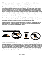
Mount all electrical parts on the top side of the board provided. To install
parts, the component should be placed flat to the board, and the leads are bent
on the backside of the board to prevent the part from falling out before
soldering (1). The part is then soldered securely to the board (2-4), and the
remaining lead length is then clipped off (5). Notice how the solder joint looks
on close up, clean and smooth with no holes or sharp points (6).
ICI1 Page 7