1
6-4
Installing Your Hardware Components
Installing Your Memory
Module
Always turn off power to the controller before removing the processor
or inserting or removing the memory module. This guards against
possible damage to the module and also undesired processor faults.
Memory modules are mounted in carriers or have connectors that are
“keyed” to guard against improper installation.
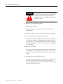
ATTENTION
!
To avoid potential damage to the memory modules,
handle them by the ends of the carrier or edges of
the plastic housing. Skin oil and dirt can corrode
metallic surfaces, inhibiting electrical contact. Also,
do not expose memory modules to surfaces or areas
that may typically hold an electrostatic charge.
Electrostatic charges can alter or destroy memory.
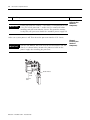
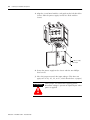
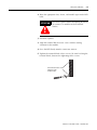
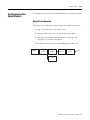
1. If the processor module is installed in the chassis, remove the
module by pressing the retainer clips at both the top and bottom
of the module and sliding it out.
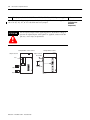
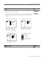
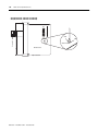
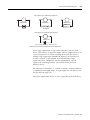
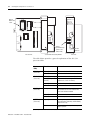
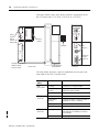
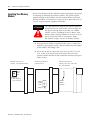
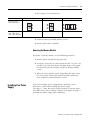
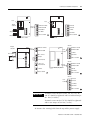
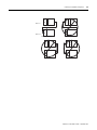
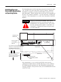
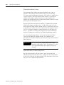
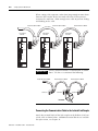
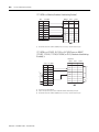
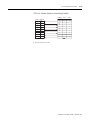
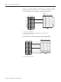
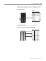
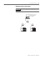
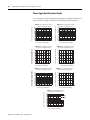
2. Locate the socket (or connector if you have an SLC 5/03, SLC
5/04, or SLC 5/05) on the processor board. Then place the
memory module into the socket or onto the connector and press
firmly in place.
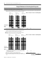
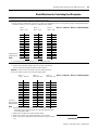
Side View of SLC Processor
1747-L511, -L514, and -L524 Series B
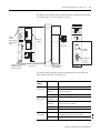
Side View of SLC Processor
1747-L524 Series C
Side View of SLC Processor
1747-L531, -L532, -L541, -L542, -L543,
-L551, -L552, and -L553
Memory
Module
Socket
Jumper J1
(Note: Jumper J1
not on 1747-L511.)
Memory
Module
Socket
Jumper J1
Publication 1747-UM011C-EN-P - December 2001
Memory
Module
Connector