1
NetVanta Unified Communications Technical Note
___________________________________________________________________________________
Installing and Configuring the Quintum
Tenor DX Gateway
Introduction
The Tenor DX is a modular T1 digital gateway used in NetVanta Unified Communications Server
installations to provide a gateway between internal (SIP) phone calls and the outside phone network
(PSTN). Voice communications from an internal phone have voice over IP (VoIP) signals converted into
digital TDM voice, which are transmitted over the PSTN.
A gateway works in conjunction with the UC server’s SIP Proxy and SIP. All telephony services are
provided through the mutual cooperation of SIP gateways, SIP telephones, SIP proxy and the Core
Application Service.
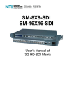
The following diagram illustrates the UC server SIP architecture and its relationship with other
components in a typical customer network.
1
Supported Features
Feature Name
Supported Notes
Accept Incoming Calls
Accept Outgoing Calls
Trunk-to-trunk connect
Calling Party Name
Calling Party Number
Answer Supervision
Disconnect detection
DTMF Tone Support (RFC2833 Compliant
Conferencing with SIP Endpoints
Direct Inward Dialing
System Music on Hold Support
Outgoing Fax Support
Incoming Fax Support
Outgoing Caller ID Creation
Unified Communication Features Supported by Gateway
Active Message Delivery
Paging Notification
Transfer—Assisted/Supervised
Transfer—Blind
Unified Communication Features Supported by Gateway
Multiple SIP Proxy Support
Interoperability Software Versions
The following gateway version was tested for interoperability:
System Description: Quintum Tenor DX
Boot Version: P106-02-00
Firmware Version: P106-12-00
2
Available with survivability option
Overview of Configuration Procedure
To provide its functionality the Tenor DX must be connected to the internal LAN (a 100 Mbps connection
is recommended) and a T1/ISDN digital line.
The Quintum Tenor DX is primarily configured using a java configuration program. The program must
be installed to configure and manage the gateway.
The basic steps for installation and configuration
1. Unpack the Tenor DX.
2. Mount the Tenor DX.
3. Connect cables.
4. Set a DHCP IP address reservation for the Tenor DX based on its MAC address.
5. Connect to console port and set IP address.
6. Run the initial configuration wizard.
7. Configure the UC server to use the Tenor DX.
NOTE: Please see the instructions provided by Quintum for information about running and configuring
the gateway.
The rest of this document provides instructions about configuring the Tenor DX for operation with the
UC server.
Address Reservation
The Tenor DX can be configured either with a reserved IP address from DHCP or a static IP address. For
routing calls out from the UC server, the Tenor DX must have an IP address that does not change.
Set IP Address and Subnet Mask
Connect a serial cable to the RS-232 port of the Tenor DX. Configure a terminal program, such as
HyperTerminal, with the following: 38,400 bits per second, 8 data bits, 1 stop bit, No parity, No flow
control.
A login prompt appears. Log in using username: admin, and password: admin.
3
It is important that the Tenor DX have a LAN IP address that does change. This can be set using a static
IP address and subnet mask compatible with the onsite LAN. To configure the IP address, do the
following:
At the Quintum prompt, enter ei to reach the Ethernet prompt, and then enter config to change to
the configuration mode.
To set the IP address, enter set ipa followed by the IP address.
To set the Subnet Mask, enter set subnetmask, followed by the subnet mask.
Enter siprd to change to the Static IP Route Directory.
To set the Default Gateway IP, enter change 1 g followed by the IP address for the default
gateway IP.
Enter submit.
Enter maint to reach the maintenance mode and then mc. Enter reset.
A confirmation message asks if you want to reset the unit. Enter yes to reset the unit and
incorporate the new settings.
Initial Configuration Wizard
To begin configuration of the Quintum gateway, you must first install the Tenor Configuration Manager.
You can either get it from the CD included with the gateway or at the Quintum support website
(http://www.quintum.com/support)
After you install and run the Tenor Configuration Manager, the following screen appears.
4
1. In most cases, by selecting Discover the program automatically detects the gateway. Select
Connect. If the program does not detect the gateway, you must select Add and manually enter
the IP address of the Quintum gateway.
2. After you select Add the following screen appears. Enter the IP address of the gateway. The login
and password is admin. After you add an address, select OK and then select Connect.
3. After you connect, a wizard opens to set up the initial configuration of the gateway. Select Next.
4. On the IP Address Configuration screen, you can choose how your gateway obtains its IP
Address and network settings. A static IP address is recommended for a gateway. Select Next> to
continue.
5
5. You can specify whether you want to obtain DNS server addresses automatically, manually
configure DNS Server addresses, or Manually Configure Static DNS Host. If you are using
DHCP, you can automatically obtain the DNS server addresses; otherwise you must manually
configure them. Select Next> to continue.
6
6. The first task is complete. Select Next> to continue.
NOTE: If you want to change any of the configuration parameters, you can navigate back through the
wizard or make changes after the initial configuration wizard.
7. The Dial Plan Configuration screen allows you to set up the dialing plan. Depending on your
region, you can choose the dial plan suitable for your country. If you are in North America,
choose either US/NANPA 7 digit local or US/NANPA 10 digit local. Select Next> to
continue.
7
8. On the next Dial Plan Configuration screen, enter your local area code, which the Tenor uses to
correctly route calls through the PSTN. Select Next> to continue.
9. You have completed the dial plan configuration. Select Next> to continue to the next step.
8
10. You must now choose the application configuration, which specifies the gateway functions. To
make and receive calls through the PSTN, choose Termination. Select Next> to continue.
11. The next screen allows you to specify the Line Configuration. Select Next> to continue.
9
12. On the next Line Configuration screen, choose the primary clock source for the PRI link. A
typical configuration requires that you choose Digital Line. Select Next> to continue.
10
13. On the next Line Configuration screen, choose the secondary clock source for the PRI link. A
typical configuration requires that you choose Internal. Select Next> to continue.
14. On the next Line Configuration screen, choose the line type for the PRI link. Select Next> to
continue.
11
15. On the next Line Configuration screen, choose the voice coding law for the digital link.
Typically, Mu-Law is used for T1 links and A-Law is used for E1 links. Select Next> to
continue.
16. On the next Line Configuration screen, choose the PRI protocol for the gateway. This setting
varies depending on the configuration of the link. Select Next> to continue.
12
17. Review the Line configuration summary screen. Select Next> to continue.
18. On the Hopoff Configuration screen, choose Yes to make sure all the calls go through the UC
server. Select Next> to continue.
13
19. On the next Hopoff Configuration screen, choose Yes to enable Hopoff Calls. Select Next> to
continue.
20. On the next Hopoff Configuration screen, configure the hopoff numbers that you want. You can
set up numbers that are allowed go through to the PSTN line. Configure these numbers based on
your location and requirements. A hopoff number would usually contain the first few digits of a
PSTN number based on your location. For example, to allow local calls you would add an entry
with 613 as the number pattern and replacement number where 613 is your local area code. If
you want to allow international numbers then you would use 011 as the number pattern and
replacement number.
14
21. Review the Hopoff Configuration summary screen. Select Next> to continue.
22. On the VoIP Routing Configuration screen, for integration with the UC server, choose SIP only.
Select Next> to continue.
15
23. On the next VoIP Routing Configuration screen, change the Primary SIP Server to the IP address
where your UC server is hosted. Select Next> to continue.
24. On the VoIP Routing Configuration screen, enter 10000 for User ID and Password. Select
Next> to continue.
16
25. Review the VoIP Routing Configuration summary screen. Select Next> to continue.
26. On the DS1 Configuration screen, if you only have one PRI link, choose Yes. Select Next>
to continue.
17
27. If you selected Yes on the previous step, the following DS1 Configuration screen appears. On this
screen, clear unused DS1 Line check boxes. Select Next> to continue.
28. Review the DS1 Configuration summary screen. Select Next> to continue.
18
29. Check the settings to make sure they are correct. You can go back and make changes if necessary.
When finished, select Accept to continue.
30. After you complete the initial configuration and reboot the Quintum gateway, navigate to the
Line Port Configuration tab. You can set up numbers that are allowed go through to the PSTN
line. Configure these numbers based on your location and requirements, and, when finished,
select Confirm/OK. Select the first icon on the toolbar to continue to the next step.
19
31. Navigate to System-Wide Configuration > Dial Plan. On the General tab, change Maximum
Dial Digit Length to 10 and Minimum Dial Digit Length to 7. You can also change other settings
like Dial Plan Country and Progress Tone Country. Select Confirm/OK.
32. Navigate to Circuit Configuration > Trunk Routing Configuration > Trunk Circuit Routing
Groups > Trunk Circuit Routing Group-1. In the Forced Routing Number box, enter the
auto-attendant identity. Typically, this is set to 10000. Select Confirm/OK.
20
33. In Trunk Circuit Routing Group-1, Navigate to the Trunk ID/Caller ID tab. Under Trunk ID
Delivery, choose Calling Party Number. Select Confirm/OK.
34. Navigate to VoIP Configuration > SIP Signaling Groups > SIP Signaling Group-1. Make sure
that Nortel is selected from the SIP Info Format list box.
21
35. Navigate to VoIP Configuration > Voice Codec-1. Set Voice Codec to G.711 Mu-law 64 kb.
Select Confirm/OK.
36. Navigate to VoIP Configuration > IP Routing Groups > IP Routing Group-default and the
ANI tab. Under the Relay Calling Name dropdown choose Relay CNAM in Invite. Select
Confirm/OK.
22
37. If you wish to modify the outgoing caller ID, navigate to Circuit Configuration > ISDN
Signaling Groups > ISDN Signaling Group-1 and the Advanced tab. Under Relay ANI,
choose Relay Default ANI TON/NPI. Under Default ANI enter the outgoing number you
wish to use. This can be any telephone number, for example, 6135999698.
38. To complete the changes, select Confirm/OK and then the submit changes button.
Enabling CNG Tone Detection for Faxing
By default, a Quintum gateway will not detect CNG tones used for faxing unless the call is directed at a
fax service. In order to receive faxes when a call is answered by a standard service (not a fax service), you
must create a file and upload it to the gateway via FTP.
To enable CNG detection:
1. Open Notepad or another text editor.
2. Put in the following line: enableCNGdetection 1
3. Save the file as var_config.cfg.
4. From your Windows PC select Start > All Programs > Accessories > Command Prompt. The
Command Prompt window is displayed.
5. Use the CD command to change to the directory on your PC in which you saved the
var_config.cfg file.
23
6. Enter ftp followed by the IP address of the unit. Press Enter.
7. Login with the username and password. The default for both is admin.
8. Use the CD command to change to the cfg directory (this is the directory on the Tenor into which
you will copy the var_config.cfg file). Depending upon the product type and software revision,
the directory structure you see in your Tenor VoIP device may be different.
9. Enter bin <Enter>.
10. Enter put var_config.cfg <Enter>
11. Restart the gateway from the Tenor Configuration Manager in Tools > Reboot Tenor.
Configuring the UC Server
After you add the gateway to your network, the UC server must be configured to handle incoming and
outgoing phone calls. For outgoing calls you must add: a SIP gateway, a dial plan entry to route calls out
through the gateway and a toll restriction entry to allow those calls. For incoming calls you must add a
Call Attendant Identity that can answer incoming calls from the gateway. These instructions are for
release 4.1 of the UC server.
Adding a Trunk Identity
1. Go to Identities.
2. Right-click the right panel and select New Identity.
3. In the first page of the Wizard, select an Attendant identity. Ensure that the Identity is associated
with the Admin profile.
4. On the following page, enter a descriptive name and enter 10000 for the Address (assuming a
standard configuration). Make sure that Default Trunk Service is the selected service.
Adding a SIP Gateway
1. Select Gateways.
2. Right-click the right panel and select New Gateway.
3. Choose Public Switched Telephone Network (PSTN) from the gateway list.
4. In the Host name field, enter the IP address of the gateway.
5. Enter a descriptive name for the gateway.
6. Save.
Configuring the Dial Plan
Incoming calls from the PSTN are already configured by having incoming calls routed to the 10000
Trunk identity. An entry or entries must be entered in the Dial Plan for outgoing calls to the PSTN.
1. Go to Communication Service -> UC Server -> Routing.
24
2. There are many possibilities here. If regular PSTN calls are to be routed out the gateway, add or
modify an entry where the Original Digits are [0-9]{7,} and select the Vega gateway. For
example:
Configuring Toll Restrictions
Configure the toll restrictions to match the requirements of your organization. Consult the NetVanta
Unified Communications Server Administrator Guide, available online at http://kb.adtran.com, for the
correct use of regular expressions in the toll restrictions to enforce corporate dialing policy. It is explained
in detail in Managing PBX Configuration Categories > Routing—Toll Restrictions.
25
Glossary of Features
Accept Incoming Calls
This feature allows an incoming call from the PSTN to be answered by the gateway and a SIP call is then
made to extension 10000.
Accept Outgoing Calls
An outgoing SIP call from the UC server results in an outgoing PSTN call.
Trunk-to-trunk connect
This feature allows an established call through the gateway, which can be extended back out the gateway
on another PSTN trunk.
Calling Party Name
The gateway detects the calling party name on an incoming PSTN call and provides that name to the UC
server.
Answer Supervision
The gateway must detect that a call has been answered. There are a number of techniques used for this,
including loop start, battery reversal and voice detection.
Disconnect detection
The gateway must detect that a call has been dropped. There are a number of techniques used for this
including loop start, battery reversal and no voice detection.
DTMF Tone Support (RFC2833 Compliant)
Calls incoming from the PSTN to the UC server are usually handled by an auto attendant. Feature
operation is implemented using DTMF tones from telephones. These tones must be sent to the UC server
as SIP packets via RFC2833.
Conferencing with SIP Endpoints
The gateway needs to support conferencing between itself and other SIP endpoints.
Direct Inward Dialing
Calls incoming from the PSTN must be automatically routed to the UC server for auto attendant
functionality.
System Music on Hold Support
The UC server supports music on hold. When PSTN callers are put on hold they hear music, if that
feature is enabled on the system.
Outgoing Fax Support
The UC server supports the transmission of faxes to standard fax machines. The gateway must support
T.38 fax transport to provide this capability.
26
Incoming Fax Support
The UC server supports the transmission of faxes to standard fax machines. The gateway must support
T.38 fax transport to provide this capability. Additionally, the gateway should support CNG tones so that
an incoming PSTN fax call can be distinguished from a voice call and handled appropriately.
Active Message Delivery
The gateway must support the UC server calling out to the PSTN to deliver voice messages.
Paging Notification
The gateway must support the UC server calling out to the PSTN to deliver pages.
Transfer—Assisted/Supervised
After a call is established between an outside PSTN call and an internal SIP device, the gateway must
allow a supervised transfer to another SIP device.
Transfer—Blind
After a call is established between an outside PSTN call and an internal SIP device, the gateway must
allow a blind transfer to another SIP device.
Multiple SIP Proxy Support
In high reliability applications if the main UC server is not available the gateway routes incoming PSTN
calls to an alternative SIP Proxy.
27