1
Installation
15
Heater Exhaust
Route the flexible exhaust in such a way that the heat cannot affect adjacent heat sensitive materials, plastic piping, electric
cables and sails etc. Make sure to use the glass / silicon protective insulating sleeve supplied in the kit to ensure surrounding
objects are protected.
If additional protection is required, it is recommended to over-sleeve with an additional layer of insulation (available from
your local Webasto marine dealer).
CAUTION
DO NOT connect the heater exhaust into the engine or generator exhaust. Doing so will result in
unacceptable back-pressure levels and may damage the heater or cause operational failure.
DO NOT install a flapper valve (clamshell) over the exhaust outlet as this will cause excessive back
pressure within the exhaust system and heater.
DO NOT cover or block the exhaust outlet while the heater is in operation.
The end of the exhaust pipe must be routed with a goose-neck bend and be pitched downward toward the outlet. Any
splash water that may have penetrated can thus drain back out again and not into the heater. This is a dry exhaust and
not water injected.
The exhaust pipe is to be kept as short as possible. The maximum length of 5 meters (16 1/2’) without muffler or 2 meters
(6 1/2’) with muffler must on no account be exceeded. The total radius of bends should not exceed 270 degrees with a
minimum bend radius of 50mm (2 in.).
The exhaust tube and exhaust components must be securely fastened using approved exhaust tube clamps and P-clips as
supplied with the heater kit.
At the lowermost point of the exhaust pipe, a condensation water drain should be installed in which condensation or excess
water collecting in the exhaust pipe can be drained off at regular intervals. Make sure to fill condensation drain with water
to provide a seal against exhaust gas leakage once drain has been installed.
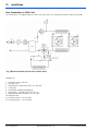
Fig. 12 Exhaust System Layout
www.webasto.us
Webasto Product N.A., Inc.
www.techwebasto.com