1
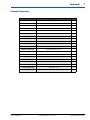
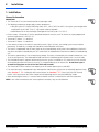
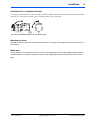
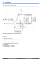
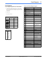
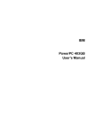
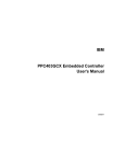
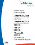
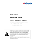
Webasto BlueCool Premium
Thermo 90 ST - Chiller
Installation Manual
CAUTION
– Improper installation or repair of Webasto heating and cooling systems can cause
fire or the leakage of deadly carbon monoxide leading to serious injury or death.
– Installation and repair of Webasto heating and cooling systems requires special
Webasto training, technical information, special tools and special equipment.
– NEVER attempt to install or repair a Webasto heating or cooling system unless you
have successfully completed the factory training course and have the technical skills,
technical information, tools and equipment required to properly complete the
necessary procedures.
– ALWAYS carefully follow Webasto installation and repair instructions and heed all
WARNINGS.
– Webasto rejects any liability for problems and damage caused by the system being
installed by untrained personnel.
Table of Contents
Contents
3
Page
Foreword
4
General . . . . . . . . . . . . . . . . . . . . . . . . . . . . . . . . . . . . . . . . . . . . . . . . . . . . . . . . . . . . . . . . 4
Scope and Purpose . . . . . . . . . . . . . . . . . . . . . . . . . . . . . . . . . . . . . . . . . . . . . . . . . . . . . . . 4
Safety and Important Information . . . . . . . . . . . . . . . . . . . . . . . . . . . . . . . . . . . . . . . . . . . . 5
Symbol Identification . . . . . . . . . . . . . . . . . . . . . . . . . . . . . . . . . . . . . . . . . . . . . . . . . . . . . 6
Heater Dimensions . . . . . . . . . . . . . . . . . . . . . . . . . . . . . . . . . . . . . . . . . . . . . . . . . . . . . . . 6
Packaged Components . . . . . . . . . . . . . . . . . . . . . . . . . . . . . . . . . . . . . . . . . . . . . . . . . . . . 7
Installation
8
General Information . . . . . . . . . . . . . . . . . . . . . . . . . . . . . . . . . . . . . . . . . . . . . . . . . . . . . . 8
Installation Site / Installation Position . . . . . . . . . . . . . . . . . . . . . . . . . . . . . . . . . . . . . . . . . . 9
Hose Connections to Chiller Unit . . . . . . . . . . . . . . . . . . . . . . . . . . . . . . . . . . . . . . . . . . . 10
Fuel Supply . . . . . . . . . . . . . . . . . . . . . . . . . . . . . . . . . . . . . . . . . . . . . . . . . . . . . . . . . . . . 12
Combustion Air Supply . . . . . . . . . . . . . . . . . . . . . . . . . . . . . . . . . . . . . . . . . . . . . . . . . . . 14
Heater Exhaust . . . . . . . . . . . . . . . . . . . . . . . . . . . . . . . . . . . . . . . . . . . . . . . . . . . . . . . . . 15
Electrical System . . . . . . . . . . . . . . . . . . . . . . . . . . . . . . . . . . . . . . . . . . . . . . . . . . . . . . . . 17
Information about Air Guidance . . . . . . . . . . . . . . . . . . . . . . . . . . . . . . . . . . . . . . . . . . . . 20
Circuit Diagrams
21
Initial Start-up
23
General . . . . . . . . . . . . . . . . . . . . . . . . . . . . . . . . . . . . . . . . . . . . . . . . . . . . . . . . . . . . . . . 23
Description and Operation . . . . . . . . . . . . . . . . . . . . . . . . . . . . . . . . . . . . . . . . . . . . . . . . 23
Technical Data
24
Troubleshooting
25
Fault lock-out . . . . . . . . . . . . . . . . . . . . . . . . . . . . . . . . . . . . . . . . . . . . . . . . . . . . . . . . . . 25
Version with Light . . . . . . . . . . . . . . . . . . . . . . . . . . . . . . . . . . . . . . . . . . . . . . . . . . . . . . . 25
www.webasto.us
Webasto Product N.A., Inc.
www.techwebasto.com
4
Foreword
1. Foreword
General
Webasto Product North America, Inc. is pleased to provide this installation manual with the Thermo 90 ST designed for the
BlueCool Premium System. When used according to the guidelines stated in this manual, you can expect to provide years
of trouble-free, enjoyable operation for your customer.
We encourage our customers to write to us with their comments or criticisms concerning this manual or product. Thank you
for your participation.
Please write to us at:
Webasto Product North America, Inc.
Technical Documentation Group
15083 North Road
Fenton MI 48430
You are also invited to fill out our online questionnaire concerning our technical documentation and web site at:
www.techwebasto.com
If you have immediate questions concerning this manual, the installation procedures within or the product itself, please call
our technical support team at: (800) 860-7866 or send a fax to: (810) 593-6001
Scope and Purpose
This manual is intended to provide the information necessary to ensure proper installation and operation of the Thermo 90
ST in conjunction with the BlueCool Premium System. Improper installation can result in unsatisfactory performance and/
or premature failure of these units. BEFORE proceeding, please read this manual completely. In the interest of product
improvement, specifications and design are subject to change without prior notice.
www.webasto.us
Webasto Product N.A., Inc.
www.techwebasto.com
Foreword
5
2. Safety and Important Information
Failure to follow the installation instructions and the notes contained therein will lead to all liability being refused by
Webasto Product. The same applies if repairs are carried out incorrectly or with the use of parts other than genuine spare
parts.
All Webasto BlueCool (WBC) products are 110 or 220 volt components that are only allowed to be installed, connected and
maintained by trained and duly certified personnel. The electrical power supply must be permanently disconnected before
any work is started on the systems.
The year in which the heater is used for the first time must be permanently recorded on the heater’s factory plate by deleting
the inapplicable year figures.
The heater must not be operated:
• In filling stations
• In places where explosive vapors or dust may build up (e.g. near fuel, coal, wood, or dust).
• In enclosed rooms (e.g. winter storage facilities)
The heater must not:
• Be exposed to temperatures of more than 248°F (120 °C) (storage temperature), otherwise the electronics may
suffer permanent damage.
The heater must:
• Be operated with the fuel specified on the factory plate.
• Be switched off if considerable quantities of smoke is generated, in case of unusual combustion noises or if you
smell fuel. Switch it off by removing the fuse. The heater must not be restarted until the unit has been checked by
personnel duly trained by Webasto.
• Be operated for 10 minutes at least once a month. The heater must be inspected by a specialist at the beginning of
the heating season or earlier.
www.webasto.us
Webasto Product N.A., Inc.
www.techwebasto.com
6
Foreword
Symbol Identification
The purpose of safety symbols is to attract your attention to possible hazardous conditions. This manual uses a series of
symbols and signal words which are intended to convey the level of importance of the safety messages. The progression of
symbols is described below. Remember that safety messages by themselves do not eliminate danger and are not a
substitute for proper accident prevention measures.
Indicates an imminently hazardous situation which, if not avoided,
WILL result in death or serious injury.
DANGER
WARNING
Indicates a potentially hazardous situation which, if not avoided,
COULD result in death or serious injury.
CAUTION
Indicates a potentially hazardous situation which, if not avoided,
MAY result in minor or moderate injury or property damage.
It may also be used to alert against unsafe practices.
These symbols are used to alert the installer to important or useful information about proper
installation of the equipment.
OR
Heater Dimensions
5
3
ø 20
45
ø 39
ø5
99
92
152
88
89
95
4
1
2
ø 20
ø 38
ø 30
99
137
1. Combustion Air Intake
2. Exhaust Fume Outlet
3. Fuel Intake
4. Coolant Inlet
5. Coolant Outlet
49
131
=
=
100
352
381
Fig. 1 Dimensions of the Thermo 90 ST
www.webasto.us
Webasto Product N.A., Inc.
www.techwebasto.com
Foreword
7
Packaged Components
Category
Description
Qty.
Intake and Exhaust
TUBE FLEX SS 38MM X 2M
1
TUBE FLEX PAK 30MM X 2M
1
CLAMP EXHAUST 1 1/2"
4
CLAMP HOSE AIR INTAKE
2
THRU HULL EXHAUST
1
FUEL LINE METAL (3/16"DIA) 25 FEET
1
COMPRESSION FITTING 3/16" COUPLING UNION
1
STANDPIPE W/COMPRESSION FITTING
1
COUPLER FUEL LINE STRAIGHT
1
CLAMP HOSE 9.5-10.5MM
2
FUEL PUMP ENCLOSURE
1
ENVELOPE WHITE 9"X12"
1
WARRANTY CARD
1
THERMO 90 ST INSTALLATION MANUAL
1
THERMO 90 ST 12V MARINE HEATER
1
HARNESS POWER / SWITCH
1
INTERNAL HARNESS THERMO 90 S
1
Parts Bag Clamps
CLAMP HOSE 13-32MM 1/2" SS MARINE GRADE
6
Parts Bag Mounting
BOLT M6 X 25 SS
4
NUT M6-1.0 SS
4
Fuel System
Manuals / Warranty
Heater Parts
www.webasto.us
Webasto Product N.A., Inc.
www.techwebasto.com
8
Installation
1. Installation
General Information
IMPORTANT
• The Thermo 90 ST must be installed outside the passenger cabin.
• The following temperature ranges apply to some components:
• ABS pipe system (G. Fischer) and fittings from -40°F - 140°F (-40°C to +60°C). Use a pipe system designed for
temperatures up to 248°F (120 °C), e.g. Hep2O made by Hepworth.
• Radial blower on the heat exchanger (arranged on inlet side) up to 131°F (55 °C)
• For this reason, a Thermo 90 ST with a specialized control unit must be used. The heater has a pre-programmed
nominal temperature of 126°F (52 °C).
• Thermo 90 ST Heater – 12 volt diesel
• Thermo 90 ST Heater – 24 volt diesel
• If the volume of water in the circuit is too small less than 2.5gal. (10 liters), the heating system may shut down
prematurely. To avoid this, a storage tank should be installed ahead of the heater.
• The heater is incorporated into the water circuit of the air conditioning unit by means of an additional, electrical 3way valve. Activation is controlled by the TECC card within the Webasto Blue Cool Premium (WBCP) air conditioning
unit.
• The heater is powered by a 12 or 24 volt battery voltage. The heater is activated by the electronic control unit via a
12 or 24 volt signal wire. The Webasto BlueCool Premium Air Conditioning Unit functions with 110 or 220 volts.
• The circulation pump (P1) operates continuously when the system is switched on. This means there is no need for
the circulating pump on the heater. As a result, it is integrated directly at the heater inlet. A cool down cycle is
assured from program version 413 of the TECC card onwards.
• The Thermo 90 ST offers excellent heat capacity to an air handler power up to 31,000 BTU.
• If an external heater is incorporated into a Webasto Blue Cool Premium System with an electrically operated 3-way
valve, function F 04: “Automatic with External Heater” or function F 05 “Heat Cycle Only with External
Heater” must be preset on the Chiller Control and the operating element must be blocked by a code.
• When connecting the heater, it is essential that the correct terminal is selected for the nominal temperature.
NOTE: If the vehicle manufacturer has issued separate instructions, they must be followed.
www.webasto.us
Webasto Product N.A., Inc.
www.techwebasto.com
Installation
9
Installation Site / Installation Position
The heater must be installed in as low a position as possible to allow the heater and circulating pump to be bled automatically. This is particularly important as the circulating pump is not self-priming.
Fig. 2 Correct installation positions for the Thermo 90 ST
Mounting the Heater
The heater must be secured with at least three M8 screws. The screws must be tightened with a torque value of 13
lb-ft. (18 Nm).
Model plate
The model plate must be positioned so that it cannot be damaged and must be clearly legible when the heater is
installed (otherwise a duplicate model plate must be used). Inapplicable years must be erased from the model
plate.
www.webasto.us
Webasto Product N.A., Inc.
www.techwebasto.com
10
Installation
Hose Connections to Chiller Unit
The Thermo 90 ST is intragrated into the Chiller unit water circuit via a electrically actuated 3-way valve assembly.
Fig. 3 BlueCool Premium System with a Thermo 90 ST
Components:
1. Stop valve at ship’s side inlet
2. Sea water filter
3. Webasto Blue Cool Premium Unit 110 / 220 volts
5. 3-way valve
6. Intermediate storage tank (optional)
7. Water heater – Thermo 90 ST 126°F (52 °C)
8. Webasto BlueCool Air Handler 110 / 220 volts
10. Expansion tank
P1 Sea water pump – 110 / 220 volts
P2 Circulating pump – 110 / 220 volts
www.webasto.us
Webasto Product N.A., Inc.
www.techwebasto.com
Installation
11
Electrically actuated 3-way valve:
Electrically actuated 3-way valves of the relevant sizes are used in chiller systems with up to 36,000 BTU.
The selection is made according to the diameter of the pipe used.
• 3-way valve 5/8" incl. fitting
• 3-way valve 3/4" incl. fitting
• 3-way valve 1" incl. fitting
The hoses must be installed without kinks and (to ensure perfect bleeding) rising if possible. Hose connections must be
supported by hose clips to prevent them slipping.
NOTE: The hose clips must be tightened with a torque value of 35 lb-in. (4 Nm).
CAUTION
The cooling system must be bled carefully before using the heater for the first time or after
replacing the water. The heater and lines should be installed in such a way as to ensure static
bleeding. Perfect ventilation can be identified by the circulating pump operating almost silently.
Poor bleeding may cause the resetting temperature limiter to trip while the heater is operating.
Fig. 4 Electrically Actuated 3-way Valve
www.webasto.us
Webasto Product N.A., Inc.
www.techwebasto.com
12
Installation
Fuel Supply
The fuel can be used from the vehicle fuel tank or from a separate fuel tank. The values for the maximum pressure at
the fuel extraction point are shown in the table below.
A sign must be affixed to the fuel filler neck warning that the heater must be switched off before refuelling.
Permissible fuel inflow
height H
At max. pressure (PSI)
in fuel line
0.00’ (0.00m)
2.9 PSI
3.28’ (1.00m)
0.16 PSI
6.56’ (2.00m)
0.44 PSI
Maximum fuel intake
height S (Ft.)
At max. negative pressure
(PSI)
in the fuel tank
0.00 (0.00m)
-1.5 PSI
1.64’ (0.50m)
-0.88 PSI
3.28’ (1.00m)
-0.29 PSI
Fig. 5 Fuel Supply
Connection to Fuel Source
The fuel can be taken from the vessels fuel tank or a separate tank
Fuel Standpipe
Sealing ring
Hole pattern
Only use a tank connector if the
fuel tank is made from metal
Tank fittings
Fig. 7 Webasto Tank Connector
Fig. 6 Fuel Pickup from the Plastic Tank
NOTE: Ensure to deburr the sharp edges from the standpipe after cutting.
NOTE: Refer to fig. 7. The fitting must be made from metal!
www.webasto.us
Webasto Product N.A., Inc.
www.techwebasto.com
Installation
13
Since the lines cannot be routed with a constant rising gradient, the internal diameter must not exceed a certain size. Air or
gas bubbles will accumulate in lines with an internal diameter of more than 4 mm and will cause malfunctions if the lines
sag or are routed downwards. The lines should not be routed downwards from the metering pump to the heater.
Unsupported fuel lines must be secured to prevent them sagging. They must be installed in such a way that they cannot be
damaged by flying debre and high temperatures (e.g. exhaust line).
Connecting two pipes with a hose
The correct procedure for connecting fuel lines with hosing is
illustrated in Fig. 8
Correct
Clip
Wrong
WARNING
Ensure that there are no leaks.
Bubble
Bubble
Installation location
Fig. 8 Pipe / Hose Connections
Before installing the metering pump, ensure that the maximum
pressure occurring at the pickup point is less than 3 PSI. It is
advisable to install the metering pump in a cool place. The
maximum ambient temperature must not exceed 104°F (40 °C) at
any time during operation.
12 V and 24 V – diesel only
The metering pump and fuel lines must not be installed within
range of the radiated heat from hot vessel parts. A heat shield must
be used if necessary.
The pump should ideally be installed near the vessels fuel tank.
Fig. 9 Metering Pump
Installation and attachment
The metering pump must be secured with the supplied vibration-damping mounting clamp. Its installation position is
limited as shown in Fig. 9 in order to ensure effective auto-bleeding.
Fuel filter
Only a Webasto filter P/N: 50487171A is permitted when a fuel filter is needed. Install vertically if possible. (See Fig.10).
NOTE: Ensure to follow the correct fuel filter direction flow marked on the side of the filter.
0° - 90°
Fig. 10 Fuel Filter
www.webasto.us
Webasto Product N.A., Inc.
www.techwebasto.com
14
Installation
Combustion Air Supply
WARNING
Asphyxiation risk! The combustion air required for the heater may only be drawn in from the outside or from
spaces that are not occupied by persons e.g. ventilated foredeck box or ventilated *engine compartment
(Diesel only).
The combustion air intake line (internal diameter at least 1 1/8” (30 mm) may be 1 1/2” (0.5 m) to 16 1/2” (5 m) long with
several bends totalling 360°. The minimum bending radius is 1 3/4” (45 mm). The combustion air intake must not be routed
above the exhaust outlet.
Where combustion air is drawn from an internal source, the combustion air tube should be routed away from the heater
with a downward pitch to prevent condensation or moisture from collecting in the tube.
Where combustion air is drawn from an external source, the end of the combustion air intake tube must be routed with a
goose-neck bend with a downward pitch toward the outlet so any water that may penetrate, can drain out and not into the
heater. A 3/16 in. (5mm) condensation weep hole must be provided at the lowest point between the goose-neck to allow
drainage of any trapped condensation or splash water.
Keep combustion air intake tube opening
clear of obstructions!
Fig. 11 External Combustion Air Intake with Drain Hole
To avoid pressure differences between exhaust gas outlet and combustion air inlet, the openings of the through-hull fittings
should be located in an area where equal pressure prevails. Do not point the inlet of the combustion air tube in the direction
of travel when intake air is drawn from an external source.
Secure the intake tube to the heater with the provided hose clamps. Ensure the fuel pump connector harness is in place in
the slot provided in the air intake port before tightening clamp. Secure the tube to the adjacent structures with P-clips or
nylon wire ties.
www.webasto.us
Webasto Product N.A., Inc.
www.techwebasto.com
Installation
15
Heater Exhaust
Route the flexible exhaust in such a way that the heat cannot affect adjacent heat sensitive materials, plastic piping, electric
cables and sails etc. Make sure to use the glass / silicon protective insulating sleeve supplied in the kit to ensure surrounding
objects are protected.
If additional protection is required, it is recommended to over-sleeve with an additional layer of insulation (available from
your local Webasto marine dealer).
CAUTION
DO NOT connect the heater exhaust into the engine or generator exhaust. Doing so will result in
unacceptable back-pressure levels and may damage the heater or cause operational failure.
DO NOT install a flapper valve (clamshell) over the exhaust outlet as this will cause excessive back
pressure within the exhaust system and heater.
DO NOT cover or block the exhaust outlet while the heater is in operation.
The end of the exhaust pipe must be routed with a goose-neck bend and be pitched downward toward the outlet. Any
splash water that may have penetrated can thus drain back out again and not into the heater. This is a dry exhaust and
not water injected.
The exhaust pipe is to be kept as short as possible. The maximum length of 5 meters (16 1/2’) without muffler or 2 meters
(6 1/2’) with muffler must on no account be exceeded. The total radius of bends should not exceed 270 degrees with a
minimum bend radius of 50mm (2 in.).
The exhaust tube and exhaust components must be securely fastened using approved exhaust tube clamps and P-clips as
supplied with the heater kit.
At the lowermost point of the exhaust pipe, a condensation water drain should be installed in which condensation or excess
water collecting in the exhaust pipe can be drained off at regular intervals. Make sure to fill condensation drain with water
to provide a seal against exhaust gas leakage once drain has been installed.
Fig. 12 Exhaust System Layout
www.webasto.us
Webasto Product N.A., Inc.
www.techwebasto.com
16
Installation
WARNING
Avoid asphyxiation! If the exhaust pipe is routed through the inside of the vessel, exhaust gas tube must be as leakproof as
possible:
• use only Webasto approved exhaust clamps and firmly tighten clamps.
• an approved exhaust sealant can be used on the inside of the exhaust tube at all connection points
• use condensation water drain
• if desired, use an optional gas tight exhaust muffler to reduce interior noise
CAUTION
• DO NOT fit the skin fitting below the water line.
• DO NOT cover the exhaust while the heater is in operation.
• DO fit the skin fitting as high as possible to avoid ingress of water.
• DO make sure exhaust clamps are tight and fit well to avoid gas escape.
• DO make sure that exhaust fumes cannot reach the air intake.
www.webasto.us
Webasto Product N.A., Inc.
www.techwebasto.com
Installation
17
Electrical System
General Information
Electrical connections are to be carried out in accordance with the circuit diagrams contained in this installation manual.
When installing the electrical system make sure that the components are installed in protected, dry areas to prevent
corrosion.
If vessel only has one battery, we recommend a second battery be installed for the operation of the heater. To avoid having
to charge the battery too often, its capacity should not be too small.
If you have highly sensitive electronic components on board, a special electrical interference suppression may become
necessary. In this case, please consult a competent specialist workshop.
When actuating the battery disconnect switch (if equipped), wait until the cool down cycle of the heater has been
completed.
Control Module / Heater Connection
The electrical connection of the heaters is undertaken in accordance with the circuit diagrams in Figures 13, 15, 17, and 18.
Thermo 90 ST Control Module
The control module offers protection type 6K9K if it is installed in the position shown in Fig. 13.
24 V
XXXXXXX_.XXXXX
Fig. 13 Thermo 90 ST Control Module, Arbitrary Installation Position
www.webasto.us
Webasto Product N.A., Inc.
www.techwebasto.com
18
Installation
TECC Program 412 and Higher with Thermo 90 ST and Electrical 3-Way Valve
Because an external water heater (Thermo 90 ST) is being installed with a BlueCool Chiller Unit, the TECC Card must be
reprogrammed for proper operation. This step must be completed in order for proper operation of the Thermo 90 ST.
DEEP PROGRAMMING MODE:
Numbering below in ** represent reference numbers in Fig 14.
14
Setting Code 2:
1. Programming Code 2: With unit on, lower temperature set-point to
59° F (15° C).
2. Turn the system off by pressing the <on /off button> - *14*.
3. Simultaneously press the <Snow Flake> and <Sun> buttons - *11*.
4. Now in deep programming mode, hit the <F> button twice. The
number 2 will be displayed *15* on the left along with the current
value code to the right *16*. e.g. 2 00
5. To change this value, use the <Snow Flake> or <Sun> buttons to
increase or decrease the value. For c5 confutations, use the
following value:
Fig. 14 Chiller Control
• Programming at nominal temperature 59°F (15 °C) Code 2
value 00 (C1 and T1 closed in heating mode)
15
16
12
11
6. To confirm a function change, hit the <F> button once to proceed to the next category and hit the <on / off>
button to confirm.
7. Change is successful when the message “NENO” is displayed.
Setting Code 9:
1.
2.
3.
4.
Programming Code 9: With unit on, raise temperature set-point to 84° F (29° C).
Turn the system off by pressing the <on /off button> - *14*.
Simultaneously press the <Snow Flake> and <Sun> buttons - *11*.
Now in deep programming mode, hit the <F> button nine times. The number 9 will be displayed *15* on the left
along with the current value code to the right *16*. e.g. 9 03
5. To change this value, use the <Snow Flake> or <Sun> buttons to increase or decrease the value. For c5
confutations, use the following value:
•
Programming at nominal temperature 84°F (29 °C) Code 9
value 03 (C2 and T1 closed in heating mode)
6. To confirm a function change, hit the <F> button once to proceed to the next category and hit the <on / off>
button to confirm.
7. Change is successful when the message “NENO” is displayed.
Setting the Proper Function:
1. To change the function mode: turn the unit on by pressing the <on / off> button.
2. Hit the <F> button until the Function category is reached. The letter F will be displayed *15* on the left along with
the current value code to the right *16*. e.g. F 04
3. To change the value, use the <Snow Flake> or <Sun> buttons to increase or decrease the value. For c5
confutations, F 04 and F05 will be the only recommended and usable selections. Refer to the descriptions
below to determine which value is correct for the end user.
• F 04 = Auto Cycle Switching with External Heat Source (AC Heat, Fuel/Water Heater, etc.) - No Reversed
Cycle Valve.
• F 05 = Heat Cycle Only with External Heat Source Alone.
4. To confirm a function change, hit the <F> button once to proceed to the next category and hit the <on / off>
button to confirm.
5. Change is successful when the message “NENO” is displayed.
For electrical connections between the TECC Card and the Thermo 90 ST, refer to Figures 14, 15, 17, and 18.
www.webasto.us
Webasto Product N.A., Inc.
www.techwebasto.com
Installation
19
Connections on the TECC Card:
R1 - Connection C1
R1 - Connection R1
R1 - Connection T1
R1 - Connection C2
R1 - Connection R2
R1 - Connection T2
Fig. 15 Chiller Unit TECC Card
www.webasto.us
Webasto Product N.A., Inc.
www.techwebasto.com
20
Installation
Information about Air Guidance
Inlets and outlets:
In principle, the air guidance in the ship is designed for air conditioning operation. This means the air is extracted at floor
level and blown out at ceiling level. By nature, cool air subsides so this arrangement provides a natural circulation of air.
In heating mode, this circulation is weaker and, theoretically, the air is only circulated by the blower.
Improvement possibilities:
One possible solution involves installing closable air outlets in addition to the aforementioned outlet grilles in the floor area.
To do this, a switch must be integrated at a suitable point in the air guidance hoses of the air handler. It is possible to change
from air conditioning to heating operation by operating the switch manually.
Principle of an Air Guidance Switch:
Fig. 16 Air Guidance Switch
Important points:
• The distance between the (hot) air outlet and the (circulating) air inlet must be at least 5’ (1.5m). (Danger of air
closed circuit)
• Consider the installation complexity (price)
• The customer must perform the changeover manually.
• Currently unavailable as a single part
www.webasto.us
Webasto Product N.A., Inc.
www.techwebasto.com
Circuit Diagrams
21
Circuit Diagrams
Circuit diagram legend for the Thermo 90 ST
1. Temperature coding (temperature at water outlet):
Refer to following circuit diagram legend for further
information.
2. Vessel Fuse
3. Vessel Blower Switch
Cable cross-sections
< 7.5 m
Item
A1
A2
B1
B2
B3
B4
E
F1
F2
F3
H1
Designation
Heater
Control module
Flame sensor
Temperature sensor
Temperature limiter/
Overheating guard
Room thermostat
Glow plug
Fuse 20 A
Fuse 5 A
Fuse 20 A
“Heating” symbol in the display
7.5 - 15 m
Comment
Flat fuse SAE J 1284
Flat fuse SAE J 1284
Flat fuse SAE J 1284
Operating indicator (in item
P2)
Operating indicator (in item
S4)
Light (in item P2)
Switch-on indicator pumping
device
Immediate heat button light,
ready indicator, switch-on
control (in item P2)
Circulating pump remote
control
for vehicle fan
Combustion air fan
Circulating pump
Vehicle fan
For programmed operation
ON/OFF
mm2
1.0 mm2
H2
Light max. 2 W
0.75 mm2
1.0 mm2
H3
H5
Symbol light
Lamp, min. 1.2 W
1.0 mm2
1.5 mm2
1.5 mm2
2.5 mm2
H6
Red LED
2.5 mm2
4.0 mm2
K3
Relay
2
2
K5
M1
M2
M3
P2
S4
Relay
Motor
Motor
Motor
Digital timer
Switch
S5
1 or 2-pin disconnecting switch Emergency off switch,
electric or pneumatic
Pumping device switch
to positive
Momentary-contact switch
Immediate heat button
remote control
Switch
Heating/Circulating pump
remote control
Switch
Battery switch in positive
12-pin plug connection
to item A1
12-pin plug connection
to item P2
Plug connector, 2-pin
to Y1
Plug connector, 2-pin
Diagnostics
12-pin plug connection
To item A2 (ST 1)
12-pin plug connection
To item A2 (ST 2)
Plug connector, 2-pin
To item A2 (ST 3)
Metering pump
Fuel pump for heater
Solenoid valve
for pumping device
0.75
4.0 mm
Cable Colors
bl
br
ge
gn
gr
or
rt
sw
vi
ws
Thermo 90 ST Circuit Diagram Legend
Blue
Brown
Yellow
Green
Grey
Orange
Red
Black
Violet
White
www.webasto.us
6.0 mm
S7
S8
S9
S10
X1
X3
X5
X6
X11
X12
X13
Y1
Y2
Webasto Product N.A., Inc.
www.techwebasto.com
22
Circuit Diagrams
Fig. 17 System Circuit for Thermo 90 ST, 12 / 24V
Fig. 18 TECC Card from Chiller Unit
www.webasto.us
Webasto Product N.A., Inc.
www.techwebasto.com
Initial Start-up
23
1. Initial Start-up
General
After you have installed the heater, bleed the water system and the fuel supply system carefully.
Conduct a trial of the heater to check all the water and fuel connections for leaks and to ensure that they are secure. If the
heater suffers a fault during operation, the fault must be located and remedied.
Description and Operation
After the heater is installed and the TECC Card is programmed to reflect Function F4 (Preferred Function), the end user will
enjoy seamless comfort control. The TECC Card will now request the Thermo 90 ST rather than reverse compressor cycling
when heat is requested.
Note: Other program functions are available. See Setting the chiller control on page 16 for further information.
Air Conditioning Operation:
Display function F1, F2 and F3 - In air conditioning mode, the 3-way valve is de-energized and remains in a spring-loaded
position. The cooled water flows through the air handler and cools the drawn in recirculated air. The water temperature at
the chiller outlet is 39 - 50°F (4 – 10 °C) depending on the sea water temperature.
Heating Mode:
Display function F4 and F5 - The 3-way valve switches to the spring loaded position if the automatic mode switches to the
heating function (F4) or if “Heating operation with external heating” (F5) is selected. This means the heater is integrated in
the water circuit and heats the water to max. 144°F (62 °C). The heat is given off by the air handler. A storage tank should
be installed ahead of the heater if the water volume in the circuit is too small less than 2 1/2gal. (10 liters).
Cool Down Mode:
To ensure adequate volumetric flow during heater cool down, the control program of the TECC card has been adapted to
cool down the heater for 5 minutes. The Cool Down is active from program version 413 onwards.
www.webasto.us
Webasto Product N.A., Inc.
www.techwebasto.com
24
Technical Data
2. Technical Data
Except where limit values are specified, the technical data below refers to the usual heater tolerances of ± 10% at an
ambient temperature of 68°F (20 °C) and at nominal voltage.
Electrical components:
The control module, motors for combustion air blower and circulating pump, glow plug, and switch are designed for either
12 V or 24 V. The temperature limiter, temperature sensor and flame sensor are identical on 12 V and 24 V heaters.
Fuel for Thermo 90 ST
The diesel fuel specified by the manufacturer must be used. There are no known negative influences due to fuel additives.
If low-temperature fuel will be used, the heater must be operated for approx. 15 minutes so the fuel line and fuel pump are
filled with the new fuel.
Heater
EC licensing symbol
Model
Heat output
Fuel
Fuel consumption
Rated voltage
Operating voltage range
Max. ambient temperature:
Heater:
- Operation
- Storage
Control module:- Operation
- Storage
Metering pump: - Operation
- Storage
Max. operating pressure (heat medium)
Capacity of the heat exchanger
Max. combustion air intake temperature
Minimum capacity of the system
Delivery rate of the circulating pump against 2 PSI
CO2 in the exhaust fumes
(normal function range)
CO2 - adjustment values at approx. 68°F (20 °C)
and geographic altitude above sea level
Heater dimensions (tolerance ± 3 mm)
* Control module installed on the heater
Weight
www.webasto.us
Operation
Max.
regulating range
Max.
regulating range
Max.
Max.
Thermo 90 ST Diesel
e1*2001/56*0019*__
Water heater with Ferro-tec technology
31,000 BTU
6,142 – 26,000
Diesel
0.29 gal./h
0.05 – 0.24 gal./h
12 or 24 V
10 - 5 or 20 - 30 V
-40° - 230°F (194°F with control module installed on the heater)
-40° - 230°F (194 °F with control module installed on the heater)
-40° - 185°F
-40° - 185°F
-40° - 140°F
-40° - 185°F
29 PSI
0.04 gal.
+40 °C
1 1/2 gal.
436 gal./h
10 - 12% by volume
Max.
3280 ft.
11.3%
L 12” (307mm) or 13.85” (352*) mm with module attached
W 5.16” (131 mm)
H 9.13” (232 mm)
10.58 lb (4,8 kg)
Webasto Product N.A., Inc.
www.techwebasto.com
Troubleshooting
25
3. Troubleshooting
Fault lock-out
• Fuel is supplied for max. 240 seconds if the flame does not start to burn.
• Fuel is supplied for max. 240 seconds if the flame goes out during operation.
• The fuel supply is shut off if the system overheats (temperature limiter is tripped). If the system overheats the button
on the temperature limiter must be reset.
Once the cause of the fault has been eliminated, the fault lock-out is cancelled by switching the heater off and on again.
If the under voltage guard switches off the system for longer than 20 seconds, the fuel supply is interrupted.
Thermo 90 ST
12 V
10.5V – 0.5V
24 V
21V – 1V
Version with Light
If the system is operated with a light, the nature of the fault is indicated by a flashing code on an indicator light during the
cool down time of the heater. After five short signals, count the long flashes:
1x
2x
3x
4x
4x
6x
7x
8x
9x
10x
11x
No start (after 2 attempts to start)
Flame failure
Under voltage or over voltage
Premature flame recognition
Flame sensor interrupt or
flame sensor short-circuit
Temperature sensor interrupt or
temperature sensor short-circuit
Metering pump interrupt or
metering pump short-circuit
Blower motor interrupt or
blower motor short-circuit or
blower motor incorrect speed
Glow plug interrupt or
glow plug short-circuit
Overheating
Circulating pump interrupt or
circulating pump short-circuit
www.webasto.us
Webasto Product N.A., Inc.
www.techwebasto.com
Notes
www.webasto.us
Webasto Product N.A., Inc.
www.techwebasto.com
Notes
www.webasto.us
Webasto Product N.A., Inc.
www.techwebasto.com
Webasto Product N.A., Inc.
15083 North Road
Fenton, MI 48430
Technical Assistance Hotline
USA:
(800) 860-7866
Canada:
(800) 667-8900
Org. 05/2005
Rev. N/A
P/N: 5000988A
www.webasto.us
www.techwebasto.com