1
Procedure of Reading This Manual
Explanation of models
This manual explains two models:
- BES-960BC (9 needles)
- BES-1260BC (12 needles)
Explanation for individual model is provided by identifying the model name. Check
the model before using the machine. The software display is BES-1260BC.
Configuration of this manual
This manual consists of the following chapters:
Chapter 1
An Introduction of Embroidery Machine
Provides information on the specifications of the embroidery machine, software
installation environment, and basic software operations.
Chapter 2
Preparation of Embroidery Machine
Describes machine installation and preparation to be conducted before starting
embroidering operation.
Chapter 3
Embroidering Procedures
Provides explanations on the operation panel and briefly reviews the flow of
embroidering processes.
Chapter 4
Selecting and Transferring Embroidery Data
Explains how to use the Embroidery Data Explorer.
Chapter 5
Editing Embroidery Data
Explains how to use the Embroidery Data Editor.
Chapter 6
Embroidering
Explains how to use the Machine Controller.
Chapter 7
Operation of Machine
Provides information on machine operation during embroidering.
Chapter 8
Creating Production Report
Explains how to use the production report program.
6
BES-960BC • BES-1260BC
Chapter 9
Maintenance
Describes appropriate maintenance of the machine.
Chapter 10
Standard Adjustment
Explains how to adjust the needles.
Chapter 11
List of Error Codes
Provides information on error codes and action to be taken.
Chapter 12
Troubleshooting
Provides troubleshooting for the machine.
Connection and Installation of Optional Equipment
Describes connections between the machine/computer and optional equipment
available.
BES-960BC • BES-1260BC
7
Contents
SAFTY INSTRUCTIONS............................................................................... 1
Procedure of Reading This Manual ........................................................... 6
Contents ....................................................................................................... 8
Chapter 1 An Introduction of Embroidery Machine
1. Specifications ..................................................................................... 16
2. Software............................................................................................... 17
2-1.
2-2.
2-3.
2-4.
2-5.
2-6.
Necessary Systems ............................................................................... 17
Configuration of Software ...................................................................... 17
Notes on use .......................................................................................... 18
Help........................................................................................................ 18
Basic Operation of Software .................................................................. 19
Handling of floppy disk ........................................................................... 23
Chapter 2 Preparation of Embroidery Machine
1. Names of Machine Components ....................................................... 26
2. Installation ........................................................................................... 28
2-1.
2-2.
2-3.
2-4.
2-5.
2-6.
2-7.
2-8.
2-9.
Transportation of Machines ................................................................... 28
Installation of Machine ........................................................................... 30
Preparation of needle bar case .............................................................. 31
Mounting of Table .................................................................................. 33
Mounting of Cotton Stand ...................................................................... 37
Lubrication to Needle Bar Case ............................................................. 39
Connection of Personal Computer to Machines (for connecting 4 sets) ..... 40
Connection of Power Supply ................................................................. 42
Installation of Software........................................................................... 43
3. Preparation for Embroidering ............................................................ 44
3-1.
3-2.
3-3.
3-4.
3-5.
3-6.
Upper Threading .................................................................................... 44
Replacement of Bobbin ......................................................................... 47
Replacing and Selecting Needle ............................................................ 48
Attachment of Embroidery Hoop and Frame ......................................... 49
Bed Retract ............................................................................................ 55
Adjustment of Thread Tension ............................................................... 57
Chapter 3 Embroidering Procedures
Functions of Operation Panel .................................................................. 60
Operation Panel ................................................................................................ 60
Switches at Machine Heads .............................................................................. 62
Switches on Tension Plate ................................................................................ 62
Flowchart of Preparation for Embroidering ............................................ 64
Run the Software .............................................................................................. 65
Turn on the Machine Power .............................................................................. 65
8
BES-960BC • BES-1260BC
Register the Machine Name .............................................................................. 65
Retrieve the Embroidery Data ........................................................................... 66
Start Embroidering ............................................................................................ 66
Chapter 4 Selecting and Transferring Embroidery Data
Functions (Command Reference) ............................................................
Description of Screen ...............................................................................
Creating a Directory ..................................................................................
Selecting Data ...........................................................................................
Copy ...........................................................................................................
68
69
70
71
73
Select from Menu .............................................................................................. 73
Drag Data .......................................................................................................... 73
Moving Data ............................................................................................... 74
Select from Menu .............................................................................................. 74
Drag Data .......................................................................................................... 74
Deleting Data .............................................................................................
Renaming Data ..........................................................................................
Finding Data...............................................................................................
Adjusting Screen Display .........................................................................
Reading Data in Floppy Disk ....................................................................
75
76
77
79
80
Reading DOS Format Data ............................................................................... 80
Other Data ......................................................................................................... 82
Reading Data in Paper Tape .....................................................................
Settings for Data Reading ........................................................................
Writing Data in DST Format ......................................................................
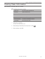
Viewing Data Information .........................................................................
85
87
88
89
Chapter 5 Editing Embroidery Data
Functions (Command Reference) ............................................................
Description of Screen ...............................................................................
Opening Embroidery Data ........................................................................
Setting Display ..........................................................................................
92
94
95
96
Centering ........................................................................................................... 96
Zoom ................................................................................................................. 96
Needle Penetration ........................................................................................... 98
Embroidering Start/End ..................................................................................... 98
Trim and pause ................................................................................................. 98
Needle Bar and Speed Range .......................................................................... 99
Thread Color ................................................................................................... 101
Tool Bar ........................................................................................................... 102
BES-960BC • BES-1260BC
9
Status Bar ....................................................................................................... 102
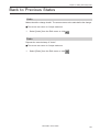
Back to Previous Status ......................................................................... 103
Undo ................................................................................................................ 103
Redo ................................................................................................................ 103
Editing ...................................................................................................... 104
Rotate .............................................................................................................. 104
Horizontal Flip ................................................................................................. 105
Vertical Flip ..................................................................................................... 105
Point Symmetry ............................................................................................... 105
Repeat............................................................................................................. 105
Resize ............................................................................................................. 107
Delete 0 Stitch ................................................................................................. 107
Insert or Delete Code ...................................................................................... 108
Insert Lock Stitch............................................................................................. 109
Changing Data ......................................................................................... 110
Changing Start ................................................................................................ 110
Changing End ................................................................................................. 111
Mask ................................................................................................................ 112
Group........................................................................................................ 113
Setting Group for Repetition ............................................................................ 114
Selecting from Menu ....................................................................................... 114
Merge ........................................................................................................ 115
Saving Data .............................................................................................. 117
Save ................................................................................................................ 117
Save As... ........................................................................................................ 118
Viewing Data Information ....................................................................... 119
Printing Data ............................................................................................ 120
Chapter 6 Embroidering
Functions (Command Reference) .......................................................... 122
When the Power to the Machine is Off ............................................................ 122
When the Power to the Machine is On ............................................................ 122
Description of Screen ............................................................................. 125
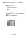
Settings before Turning On the Machine .............................................. 126
Displaying the Tool Bar ................................................................................... 126
Displaying the Status Bar ................................................................................ 127
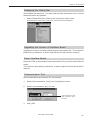
Upgrading the Version of Interface Board ....................................................... 127
Resetting Interface Board ............................................................................... 127
Communication Port........................................................................................ 127
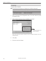
Language ........................................................................................................ 128
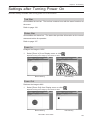
Settings after Turning Power On ........................................................... 129
Tool Bar ........................................................................................................... 129
10
BES-960BC • BES-1260BC
Status Bar ....................................................................................................... 129
Zoom In ........................................................................................................... 129
Zoom Out ........................................................................................................ 129
Zoom In Specified Range ................................................................................ 130
Fit to Window .................................................................................................. 130
Whole Pattern ................................................................................................. 130
Grid ................................................................................................................. 131
Hoop ................................................................................................................ 131
Needle Penetration ......................................................................................... 132
Thread Color ................................................................................................... 132
Needle Bar and Speed Range ........................................................................ 132
Setting Needle Bar .......................................................................................... 133
Setting Ranges ................................................................................................ 135
Grid Setting ..................................................................................................... 136
Renaming Machine ......................................................................................... 136
Viewing Machine Information .......................................................................... 137
Design Information .......................................................................................... 137
Setting Window Display .................................................................................. 137
Minimizing and Aligning Windows ................................................................... 138
Language ........................................................................................................ 140
Copying Data to Other Machines .................................................................... 140
Configuration ................................................................................................... 141
Upgrading the Machine Program .................................................................... 141
Setting the Machine ................................................................................ 142
Same Needle Bar ............................................................................................ 142
Same Speed Range ........................................................................................ 143
Speed Range .................................................................................................. 144
Head Operation Suspend ................................................................................ 144
Hoop Feed Position ......................................................................................... 145
Embroidery Area ............................................................................................. 146
Embroidery Hoop ............................................................................................ 146
Thread Trimming ............................................................................................. 149
Boring .............................................................................................................. 150
Thread Breakage Sensor ................................................................................ 151
Automatic Step Back ....................................................................................... 152
Automatic Hoop Feed ..................................................................................... 152
End of Embroidery .......................................................................................... 153
Meuding .......................................................................................................... 154
Adjust .............................................................................................................. 155
Default Settings ............................................................................................... 156
Show Setting ................................................................................................... 157
Load Setting .................................................................................................... 158
Save Setting .................................................................................................... 159
Load Hoop ....................................................................................................... 160
BES-960BC • BES-1260BC
11
Embroidering ........................................................................................... 162
Starting Embroidering ..................................................................................... 162
Moving the Home Position ..................................................................... 164
Step-forward/Step-back .......................................................................... 165
Entering in the Step-forward/Step-back Mode ................................................ 165
Setting Step-forward/Back Distance or Timing ............................................... 166
Stepping Forward/Back ................................................................................... 167
Resuming Embroidering.................................................................................. 168
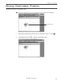
Moving Embroidery Position.................................................................. 169
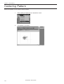
Centering Pattern .................................................................................... 170
Saving Data .............................................................................................. 171
Save ................................................................................................................ 171
Save As ........................................................................................................... 171
Test ........................................................................................................... 173
Running Other Programs ....................................................................... 174
Chapter 7 Operation of Machine
1. Operating Procedures ...................................................................... 176
1-1.
1-2.
Power Source ...................................................................................... 176
Preparation for Embroidering ............................................................... 176
2. Resetting Emergency Stop .............................................................. 177
3. Permission for Hoop Movement ...................................................... 177
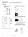
4. Measures against Thread Breakage ............................................... 178
4-1.
4-2.
Remedies ............................................................................................. 178
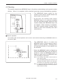
Mending ............................................................................................... 179
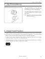
5. Jog Embroidering ............................................................................. 181
6. Hoop Feed Position .......................................................................... 181
7. Area Check ........................................................................................ 182
7-1.
7-2.
External Tracing ................................................................................... 182
Automatic Hoop Movement in Area ..................................................... 182
8. Jog Switches ..................................................................................... 183
8-1.
8-2.
Hoop Movement to Start Position ........................................................ 183
Inching Mode during Embroidering (Forcible Hoop Movement) .......... 184
Chapter 8 Creating Production Report
Functions (Command Reference) .......................................................... 186
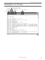
Descriptions of Screen ........................................................................... 187
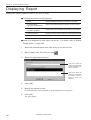
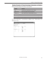
Displaying Report.................................................................................... 188
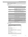
Display Example of Details ............................................................................. 189
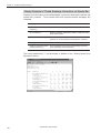
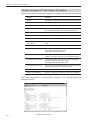
Display Example of Thread Breakage Information Needle Bar....................... 190
Display Example of Thread Breakage Information in Pattern ......................... 191
12
BES-960BC • BES-1260BC
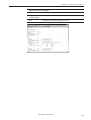
Display Example of Output Information........................................................... 192
Display Example of Total Output Information.................................................. 194
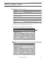
Setting Display Items .............................................................................. 195
General ........................................................................................................... 195
Details .............................................................................................................196
Thread Breakage Information on Needle Bar ................................................. 197
Thread Breakage Information in Pattern ......................................................... 197
Output Information .......................................................................................... 198
Total Output Information ................................................................................. 199
Recess Time Setting ....................................................................................... 200
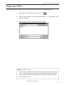
Save As CSV... ......................................................................................... 201
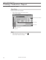
Printing Production Report .................................................................... 202
Page Setup ..................................................................................................... 202
Print ................................................................................................................. 202
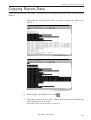
Copying Report Data ............................................................................... 203
Deleting Report ........................................................................................ 204
Chapter 9 Maintenance
1. Cleaning Rotary Hook ...................................................................... 206
2. Oiling .................................................................................................. 207
3. Greasing ............................................................................................ 209
3-1.
3-2.
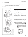
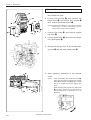
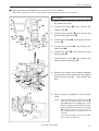
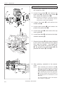
Head .................................................................................................... 209
Feed Guide Section ............................................................................. 213
Chapter 10 Standard Adjustment
1.
2.
3.
4.
5.
6.
Adjusting Needle Bar Height ...........................................................
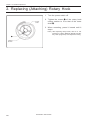
Replacing (Attaching) Rotary Hook ................................................
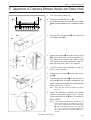
Adjustment of Clearance Between Needle and Rotary Hook .......
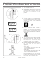
Adjustment of Timing Between Needle and Rotary Hook ............
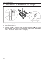
Adjustment of Presser Foot Height ................................................
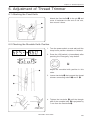
Adjustment of Thread Trimmer .......................................................
6-1.
6-2.
216
220
221
222
224
225
Attaching the Fixed Knife ..................................................................... 225
Checking the Movable Knife Position .................................................. 225
Chapter 11 List of Error Codes
Chapter 12 Troubleshooting
Mechanical Section ................................................................................. 232
Electrical Section .................................................................................... 234
BES-960BC • BES-1260BC
13
Personal Computer Section ................................................................... 235
Connection and Installation of Optional Equipment
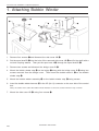
1. Attaching Bobbin Winder................................................................. 238
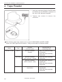
2. Tape Reader ...................................................................................... 240
14
BES-960BC • BES-1260BC
Chapter 1
An Introduction of Embroidery Machine
Chapter 1 An Introduction of Sewing Machine
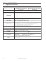
1. Specifications
Embroidery machine used
Application
Pattern embroidery
Sewing speed
Maximum 1000 spm
12 needle embroidery machine head
(six-head type)
Sewing area
450 (V) x 400 (H) mm (border frame area)
430 (V) x 300 (H) mm (tubular square hoop area)
85 (V) x 360 (H) mm (cap frame area)
450 (V) x 600 (H) mm (with bed retracted or with head control)
Feed system
By timing belt and stepping motor drive
Stitch length
0.1 ~ 12.7 mm (minimum pitch: 0.1 mm)
Storage medium
Thread trimming
Needle thread breakage
Power supply
Weight
Dimensions
Options
16
9 needle embroidery machine head
(six-head type)
3.5 2DD floppy disk (Tajima format)
Paper tape with 25.4 mm width/8 holes (Tajima, Barudan, Zanks)
3.5 2HD floppy disk (the equivalent to Tajima format)
3.5 2DD floppy disk (Barudan FDR/FMC format)
Automatic thread trimmer
Needle thread breakage detector
Single phase 200 V, 50/60 Hz, 1.7kVA
720 kg
720 kg
(Before assembly) 3650 (W) x 810 (L) x 1650 (H) mm
(After setup)
3650 (W) x 1400 (L) x 1650 (H) mm
(Distance between machine heads) 400 mm
Paper tape reader, Embroidery hoops in different sizes, Bobbin winder,
Parts for boring
BES-960BC • BES-1260BC
Chapter 1 An Introduction of Embroidery Machine
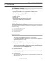
2. Software
2-1 Necessary Systems
The following systems are needed for installing the software.
• Personal computer with a CPU of Intel Pentium 133 MHz or above
(150 MHz or above is recommended.)
• Memory of 16 MB or above (32 MB or above is recommended.)
• Free space of 100 MB or above in the hard disk
• 3.5 floppy disk drive
• CD-ROM drive
• Video card of 1024 x 768 resolution in 256 colors
(1280 x 1024 in 65000 colors is recommended.)
• Windows 95
2-2 Configuration of Software
This software is mainly composed of the following four programs. The software is
provided on CD-R.
(1) Embroidery Machine Controller
(2) Embroidery Data Explorer
(3) Embroidery Data Editor
(4) Production Report
Program Functions
(1) Machine Controller
This program controls embroidering operation of the machine.
A embroidering status can be displayed on the screen in real time, and data for
operating the machine can be set.
(2) Embroidery Data Explorer
This program handles files of embroidery data on patterns.
Transmission of embroidery data to the machine, as well as copy, move and
retrieval of a file are available by means of this program. Embroidery data can
be converted from the paper tape or floppy disk.
(3) Embroidery Data Editor
This program allows editing of data on embroidering operation including scaling,
rotation, color change, etc.
(4) Production Report
This program is for collecting data on actual embroidering operation and
calculating output, etc.
BES-960BC • BES-1260BC
17
Chapter 1 An Introduction of Embroidery Machine
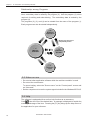
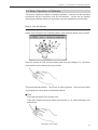
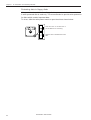
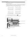
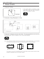
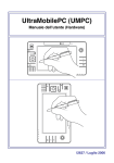
Relationship among Programs
When the software is started, the program (1) for actuating the machine starts first.
Next, embroidery data is called by the program (2). Use the program (3), when
required, for editing and embroidering. The embroidery data is totaled by the
program (4).
The programs (2), (3), and (4) can be started from the menu of the program (1).
Each program can also be started independently.
(2)
Embroidery
Data Explorer
Effective only when this is
independently started
(1)
Machine
Controller
(3)
Embroidery
Data Editor
(4)
Production
report
2-3 Notes on use
• Do not start other application software while the machine controller is used.
• Do not set the screen saver.
To cancel setting, select the "Screen saver" on the "Control panel" screen and
set "Not used".
• Set the computer not to use the system agent included in the Windows 95 PLUS.
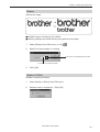
2-4 Help
The software is equipped with an on-line help function as an accessory.
Click
, then the icon of the desired item. A message is displayed to explain the
meaning and usage of the item. Pressing the [F1] key brings up the help screen of
the application for your reference.
18
BES-960BC • BES-1260BC
Chapter 1 An Introduction of Embroidery Machine
2-5 Basic Operation of Software
This section explains the basics of using the software. It covers only the operating
procedures that are commonly used for the software. If there are any special
operating procedures inherent to a program, they are explained in each section.
How to Use the Mouse
When selecting an icon or a menu displayed on the screen, move the white arrow
pointer on the screen to the required position, then press the button on the mouse.
Place the mouse on a flat, smooth surface and move it by sliding on it. The white
arrow pointer moves along the mouse motion.
The mouse has two buttons. The left one is used in general. There are three ways
of operating the mouse button as described below:
■ Click
Press the left button of the mouse once.
"Click [xx]" means moving the white arrow pointer to "xx" and pressing the left
button once.
BES-960BC • BES-1260BC
19
Chapter 1 An Introduction of Embroidery Machine
■ Double-click
Press the left mouse button twice continuously. Do not leave a long pause in
between.
"Double-click [xx]" means moving the white arrow pointer to "xx" and pressing
the left button twice continuously.
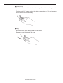
■ Drag
Move the mouse while holding down the left button.
Dragging is used for defining an area.
20
BES-960BC • BES-1260BC
Chapter 1 An Introduction of Embroidery Machine
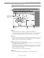
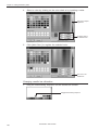
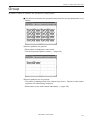
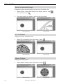
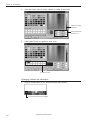
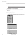
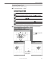
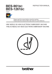
Names of Screen Components
Names of major components on the screen of the machine controller are described
below:
Menu
Tool bar
Upward
movement
Dimmed icons cannot
be used unless an
appropriate item is
selected.
Scroll bar
Downward
movement
Leftward movement
Status bar
Rightward movement
■ Menu
Processing of software is carried out by giving relative commands.
Commands are divided in groups and stored in each menu. The menu displayed
on the screen changes depending on the program which is currently active.
■ Tool bar
A command is executed by clicking a relative icon (illustrated button) on the
screen. If it is hard to recognize icons from illustrations, move the white arrow
pointer to the icon. The name of the icon is displayed.
■ Scroll bar, scroll box, and scroll arrow
Some patterns may not be displayed entirely on the screen. Use the scroll bar to
see hidden parts of the pattern into view.
When displaying the right part, for example, click the scroll arrow at the right end.
The box in the scroll bar moves to the right. By dragging the scroll box to the
right, the screen can scroll quickly.
The vertical scroll bar can be used in the same way.
■ Status bar
This bar is for displaying a brief description of the selected command.
BES-960BC • BES-1260BC
21
Chapter 1 An Introduction of Embroidery Machine
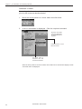
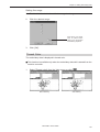
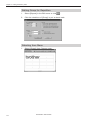
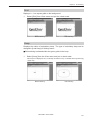
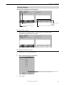
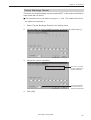
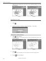
Selection of Menu
Processing of software is carried out by giving a command. A command can be
given by the mouse as described below:
1.
Move the arrow pointer to a menu name and click there.
2.
A list of commands is displayed. Click the required command.
Dimmed commands
cannot be used unless
an appropriate item is
selected.
Commands with a s mark
have sub menus.
The check mark (√)
indicates that the
command is selected.
When the arrow pointer is moved to another menu while a list of commands is displayed, those
of the latter menu are displayed.
22
BES-960BC • BES-1260BC
Chapter 1 An Introduction of Embroidery Machine
2-6. Handling of floppy disk
Do not force open the shutter for
direct contact with the magnetic
area.
Do not bring disks near magnetic
matters such as magnetic
screwdriver or the back side of the
programmer.
Do not store floppy disks in an
extremely high or low ambient
temperature.
Do not use floppy disks under high
humidity.
Do not use or store floppy disks in a
dusty place.
Do not store floppy disks under
direct sunlight.
Do not bend the disk. Do not put
things on the disk.
Avoid contact with solvent or drink.
Do not remove the disk out of the drive during the access lamp is lit.
BES-960BC • BES-1260BC
23
Chapter 1 An Introduction of Embroidery Machine
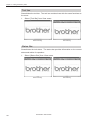
Protecting data in floppy disks
Write-protection is available for a floppy disk to prevent undesired data deletion.
A write-protected disk is read-only. It is recommended to provide write-protection
for disks which contain important data.
To do so, slide the write-protect notch to open the slot as shown below.
Slide the notch in this direction to
prevent data loss or overwriting.
Slide the notch in this direction to write
data.
24
BES-960BC • BES-1260BC
Chapter 2
Preparation of Embroidery Machine
Chapter 2 Preparation of Embroidery Machine
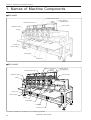
1. Names of Machine Components
■ BES-960BC
Thread tension switch
Thread guide B
Thread
Thread guide C
guide A
Thread tension dial
Cotton stand
Operation panel
Pulley
Control box
Power switch
F table
Head switch
Leg
Thumb bolt␣ ␣ ␣ ␣ ␣
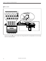
■ BES-1260BC
Thread tension switch
Thread
guide A
Thread tension dial
Operation panel
Cotton stand
Pulley
Control box
Power switch
F table
Head switch
Leg
Thumb bolt␣ ␣ ␣ ␣ ␣
The machine heads are numbered 1 to 6 from the right front.
26
Thread guide B
Thread guide C
BES-960BC • BES-1260BC
Chapter 2 Preparation of Embroidery Machine
■ Accessories
Standard Accessories
Embroidery hoop
• Tubular square hoop 30 x 43 (6)
• Tubular round arm set R (6)
• Tubular round arm set L (6)
Optional Accessories
• Holder base 30 x 43 (6)
Other embroidery hoops in different sizes
• Sash frame assembly
* Other Tajima embroidery hoops that can
be used with BAS-412A and 416A
• Cap frame (6)
Cap frame drive assembly (6)
Base frame set (12)
Set frame base set (1)
Others
F table assembly
• Paper tape reader
• Bobbin winder
• Parts for boring
BES-960BC • BES-1260BC
27
Chapter 2 Preparation of Embroidery Machine
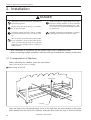
2. Installation
DANGER
Embroidery machines should be installed only
by trained engineers.
Electric wiring should be laid by your distributor or electric experts.
A machine weighs more than 720 kg. Installation should be carried out by 4 or more workers.
Install a machine in a place away from a highfrequency welding machine or other machines
that may generate a strong electric noise. Failure to do so may cause the embroidery machine
to malfunction.
Establish grounding as designated. Improper
grounding may result in an electric shock.
Do not connect the power source until installation is completed. Doing so may start the machine unintentionally through an accidental
activation of the START switch, resulting in
bodily injuries.
* After installation is completed, get the power supply from a dedicated outlet.
* When connecting multiple machines, exercise care not to exceed the capacity of the outlet.
2-1 Transportation of Machine
When relocating the machine, push the steel frame.
Note) Never push the cover or carriage.
■ When using a fork lift
Center pillar
a
a +20
Lift forks
Open the forks of the lift approximately 10 cm to the right from the even position to the center
pillar viewed from the rear of the machine, and pass them under the legs to lift the machine.
28
BES-960BC • BES-1260BC
Chapter 2 Preparation of Embroidery Machine
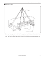
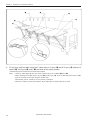
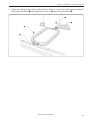
■ When using a crane
Rope
L-shaped steel
Rectangular bar
Place two rectangular bars on the four L-shaped steels on the bottom of the machine steel
frame. Loop four ropes around the bars and lift the machine.
Note) When lifting the machine, make sure that the ropes do not contact the machine table or the tension plate.
BES-960BC • BES-1260BC
29
Chapter 2 Preparation of Embroidery Machine
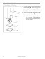
2-2 Installation of Machine
1. Place the attached cushion sheets w and
leveling plates e under the four level
adjusters q. The leveling plates e should
be placed above the cushion sheets
respectively.
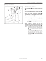
2. Secure the four level adjusters q on the
ground using the nuts r so that the
machine will be stable.
Note) If the floor is not strong enough, the embroidery machine may be rocked during operation. In such a case, it is recommended that a
secure base of concrete be placed below the
embroidery machine.
r
q
e
w
30
BES-960BC • BES-1260BC
Chapter 2 Preparation of Embroidery Machine
2-3 Preparation of needle bar case
■ BES-960BC
1. Loosen the bolt q, and move the needle case w to the left.
2. Press the change bracket collar r against the change case base e on the light, while pressing
the change bracket collar t against the change case base y on the left, and tighten the bolt
q. Check that needles at needle bar No.1 and 9 are inserted into the needle plate holes
smoothly.
Notes) • Check that the connecting shaft u does not have backlash in the horizontal direction.
• If the bolt i of the change bracket collar on the right is loosened, it may be dislocated during adjustment of the needle bar case w. Do not loosen this bolt.
BES-960BC • BES-1260BC
31
Chapter 2 Preparation of Embroidery Machine
■ BES-1260BC
Bridge
q
Connecting shaft
Fixing bracket
Fixing bracket B
Remove the bolts q ,and then detach the fixing bracket B for transportation from the bridge
and the connecting shaft.
32
BES-960BC • BES-1260BC
Chapter 2 Preparation of Embroidery Machine
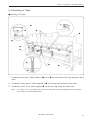
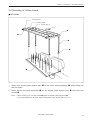
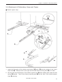
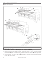
2-4 Mounting of Table
■ Mounting of F table
q
r
q
w
q
w
e
e
w
1. Tentatively mount the F table guides U q and L w on both sides of the legs using two bolts
each.
2. Tentatively mount there F table supports F e on the leg front using two bolts each.
3. Tentatively mount five F table stoppers r on the rear legs using two bolts each.
Note)
• The steps 1 and 3 are required only when the F table set is purchased separately from the machine.
• The F table is a standard attachment.
BES-960BC • BES-1260BC
33
Chapter 2 Preparation of Embroidery Machine
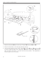
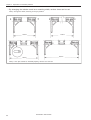
o
i
Pin
t
y
u
q
Lower by 1 mm
e
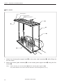
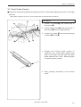
4. Mount four thumb bolts i each on the rear of F table R t, M (2 pcs.) y, and L u.
5. Mount five thumb bolts on the steel pipe below the front leg.
6. Insert the pins attached to the rear of the F table R t, M (2 pcs.) y, and L u into the cover o
on the leg. Adjust the height of the F table guide U q and the F table support F e so that the
table top surface will become 1 mm lower than the bed top surface. After adjustment is
finished, tighten each bolt securely.
34
BES-960BC • BES-1260BC
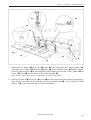
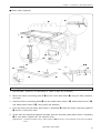
Chapter 2 Preparation of Embroidery Machine
r
e
i
w
u
y
e
t
w
7. Dismount the F table R t, M (2 pcs.) y, and L u once, and lower the F table support F e.
Then, place the F table R t, M (2 pcs.) y, and L u on the F table guide L w bending section.
Fix the F table support F e at this height and insert the pins on the rear of the F table R t, M
(2 pcs.) y, and L u into the holes of the F table stopper r.
Note) Fix the F table stopper and the F table guide L securely at this position.
8. Insert the F table R t, M (2 pcs.) y, and L u into the upper and lower positions respectively,
then check if the table can be securely fixed by the thumb bolts i. If not, shift the F table
support F e to the right and left for further adjustment.
BES-960BC • BES-1260BC
35
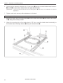
Chapter 2 Preparation of Embroidery Machine
u
y
t
!0
o
!0
9. Fix the legs and the table using the F table stays A (3 pcs.) o and B (2 pcs.) !0 while the F
table R t, M (2 pcs.) y, and L u are fixed at the upper position.
* Dismounting can be carried out in the reverse procedures.
Note)
• Use two F table stays (B) with one notch at both ends of the F table R t and L u.
• When mounting the F table stays A (3 pcs.) o and B (2 pcs.) !0, fit the F table stay notch into the table,
then fix the notch to the legs using the thumb bolts.
Dismounting can be carried out in the reverse procedures.
• When the F table is at the lower position, the F table stays A and B need not be used.
36
BES-960BC • BES-1260BC
Chapter 2 Preparation of Embroidery Machine
2-5 Mounting of Cotton Stand
■ BES-960BC
Thread guide C
Thread guide B
Thread guide A
Front
r
e
w
t
q
1. Attach four thread guide support bars w to the cotton stand assembly q, while fitting into
the four holes.
2. Mount the thread guide assembly e on the thread guide support bars w using the four
screws r.
Note)
• When mounting, use one flat washer t below the thread guide support bar w.
• Pay careful attention to the front and back directions of the thread guides (A, B, C).
BES-960BC • BES-1260BC
37
Chapter 2 Preparation of Embroidery Machine
■ BES-1260BC
Thread guide C
Thread guide B
Thread guide A
Front
r
e
w
t
q
1. Attach four thread guide support bars w to the cotton stand assembly q, while fitting into
the four holes.
2. Mount the thread guide assembly e on the thread guide support bars w using the four
screws r.
Note)
• When mounting, use one flat washer t below the thread guide support bar w.
• Pay careful attention to the front and back directions of the thread guides (A, B, C).
38
BES-960BC • BES-1260BC
Chapter 2 Preparation of Embroidery Machine
2-6 Lubrication to Needle Bar Case
Proper lubrication is necessary for keeping the machine head in good condition.
CAUTION
Turn off the power switch before starting any cleaning work, otherwise the machine may operate if the start
switch is pressed by mistake, which could result in injury.
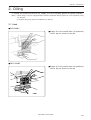
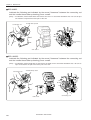
Before operating the machine for the first
time after unpacking or after leaving the
machine without operation for a long
period of time, supply one or two drops of
oil to two sections of the needle bar. (See
the left figure.)
Note)
• Use the Brother's specified embroidery machine oil (Nisseki Embroidery Lube No. 10
or the equivalent).
• Supplying an excessive amount of oil will
cause dripping onto the material.
BES-960BC
BES-1260BC
BES-960BC • BES-1260BC
39
Chapter 2 Preparation of Embroidery Machine
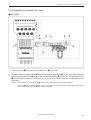
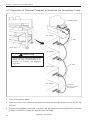
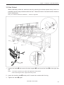
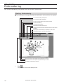
2-7 Connection of Personal Computer to Machines (for connecting 4 sets)
Interface board
(1st machine)
RC
cable
IF cable
Control box
(2nd machine)
CAUTION
Before inserting or removing IF cables or RS
cables, turn off the power switches of the
machine, the computer, and peripheral
equipment.
IF cable
(3rd machine)
(4th machine)
Terminator
(Be sure to attach
a terminator.)
1. Turn off the power switch.
2. Open the cover of the personal computer and insert an interface board into the slot for the
PCI bus.
3. Connect the interface board male connector and the personal computer RS-232C connector
(COM1 or RS-232C-1) using the attached short RS cable.
40
BES-960BC • BES-1260BC
Chapter 2 Preparation of Embroidery Machine
4. Connect the interface board female connector and the control box connector SBUS1 of the
first machine using an IF cable.
(Terminator)
5. Connect the control box connector SBUS2 of the first machine and the control box connector
SBUS1 of the second machine using an IF cable.
6. Connect the control box connector SBUS2 of the second machine and the control box
connector SBUS1 of the third machine using an IF cable.
7. Connect the control box connector SBUS2 of the third machine and the control box connector
SBUS1 of the forth machine using an IF cable.
8. Attach a terminator to the control box connector SBUS2 of the forth (last) machine.
* The IF cables used for connection are identical. There is no difference between the two ends
of the IF cable.
* The order of connecting four machines is arbitrary.
* The maximum number of connecting machines is four.
* A terminator should be connected to the connector SBUS2 of the lastly connected machine.
Connection to SBUS1, 2 can be interchangeable.
* Do not connect anything to the RS-232C connector.
Optional paper tape reader cannot be connected to this connector.
BES-960BC • BES-1260BC
41
Chapter 2 Preparation of Embroidery Machine
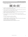
2-8 Connection of Power Supply
■ Uninterruptive power supply
This unit is for protecting a personal computer from commercial power interruption, voltage drop, and
external noise. Use of an uninterruptive power supply is strongly recommended.
Note) This unit is not an attachment of the Brother's embroidery machine, and should be purchased separately
from a different source.
Note) When using an uninterruptive power supply, be sure to establish grounding.
Uninterruptive power supply unit
Grounding cable
■ Grounding
Note)
• When connecting the power supply, make sure to connect it to the grounding cable (with green and
yellow stripes).
• When plugging in the outlet, use a plug suited to the outlet.
Grounding cable
42
BES-960BC • BES-1260BC
Chapter 2 Preparation of Embroidery Machine
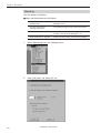
2-9 Installation of Software
Use an attached CD-R for installing software. If a personal computer with no CD-R drive unit is
used, connect a drive unit to the computer.
1. Set the CD-R for installation.
Setting the CD-R starts the installation program automatically.
2. The screen for user registration is displayed. Input your name and department. Click [OK]
after inputting is finished.
3. Check the user information. Click [OK] if the contents are correct.
4. Specify a folder for setup.
5. Click [TO NEXT] to start installation.
6. After setup is properly finished, a message is displayed.
7. Click [OK] to complete installation.
BES-960BC • BES-1260BC
43
Chapter 2 Preparation of Embroidery Machine
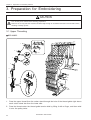
3. Preparation for Embroidering
CAUTION
Turn off the power switch before starting preparation.
Failure to do so may start the machine unintentionally through an accidental activation of the START switch,
resulting in bodily injuries.
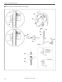
3-1 Upper Threading
■ BES-960BC
1
Needle Bar No.3,6,9
No.2,5,8
2
No.1,4,7
3
4
5
6
7
1. Pass the upper thread from the cotton stand through the hole of the thread guide right above
each cotton stand bar from the lower side.
2. Pass the thread under the thread guide tension disk by lifting it with a finger, and then wind
it onto the pulley twice.
44
BES-960BC • BES-1260BC
Chapter 2 Preparation of Embroidery Machine
3. Pass the thread through the hole of the upper thread guide (U), wind it into the tension disk
clockwise once, and place it on the spring.
4. Pass the thread through each hole of the upper thread guide (U) and the thread guide (C).
5. After passing the thread through the hole of the thread guide (U), insert the thread into the
right side of the inner thread guide, and pass it through the hole of the thread take-up.
6. Bring the thread to the inner thread guide again to insert it into the hole from the upper
section, then into the lower thread guide.
7. Pass the thread through the hole of the needle bar thread guide, then pass it through the
needle eye, without passing it through the presser foot.
■ BES-1260BC
1
Needle Bar No.3,6,9,12
No.2,5,8,11
2
No.1,4,7,10
3
4
5
6
7
1. Pass the upper thread from the cotton stand through the hole of the thread guide right above
each cotton stand bar from the lower side.
2. Pass the thread under the thread guide tension disk by lifting it with a finger, and then wind
it onto the pulley twice.
BES-960BC • BES-1260BC
45
Chapter 2 Preparation of Embroidery Machine
3. Pass the thread through the hole of the upper thread guide (U), wind it into the tension disk
clockwise once, and place it on the spring.
4. Pass the thread through each hole of the upper thread guide (U) and the thread guide (C).
5. After passing the thread through the hole of the thread guide (U), insert the thread into the
right side of the inner thread guide, and pass it through the hole of the thread take-up.
6. Bring the thread to the inner thread guide again to insert it into the hole from the upper
section, then into the lower thread guide.
7. Pass the thread through the hole of the needle bar thread guide, then pass it through the
needle eye, without passing it through the presser foot.
46
BES-960BC • BES-1260BC
Chapter 2 Preparation of Embroidery Machine
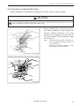
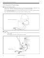
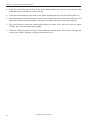
3-2 Replacement of Bobbin
Note) Remove dust, lint and oil from the bobbin case before replacement.
■ Removing bobbin case
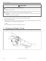
1. Open the rotary hook cover B q.
w
2. Hold the knob w and take out the bobbin
case.
3. Close the knob and take out the bobbin e.
q
e
■ Replacing bobbin
1. Put a new bobbin in the bobbin case.
2. Slide the thread under the tension spring
t through the notch r.
Pull out by about
50 mm
3. Pull out the thread from the hole of the
tension spring t.
4. Pull out the thread by about 50 mm.
t
r
■ Attaching bobbin case
w
1. Hold the knob w and attach the bobbin
case securely.
2. Close the rotary hook cover B q.
q
BES-960BC • BES-1260BC
47
Chapter 2 Preparation of Embroidery Machine
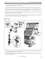
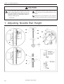
3-3 Replacing and Selecting Needle
■ Removing needle
Loosen the set screw q and remove the needle
q.
■ Attaching needle
q
With the flat side facing the front, insert the
needle all the way until it meets the end of the
needle bar. Tighten the set screw q firmly.
w
Note)
• Set the needle so that the notched part will
come on the rotary hook side.
• The needle should not be angled to the left
(when viewed from the front).
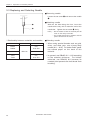
* Relationship between materials and needles
Material
Needle
Denim
Leather
Handkerchief
Shirt
Towel
48
Needle thickness
#14,
#16, #18
DB x K5
#9, #10
#11,
#12, #13
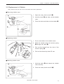
■ Selecting needle
• When using special threads such as gold,
silver, and rame yarn, use a heavy-duty
needle (#11 ~ #16). For better finish, paste
the waxed paper on the back of the
material.
• In general, use DBxK5 #11 ~ #18 according
to the material thickness. For knitted
materials, use DBxK23 #11 because its
rounded point prevents the knit thread from
breaking.
BES-960BC • BES-1260BC
Chapter 2 Preparation of Embroidery Machine
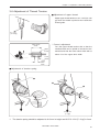
3-4 Attachment of Embroidery Hoop and Frame
■ Tubular square hoop
r
e
w
q
y
u
t
q
1. Insert the fixing pins of the tubular round arms R q and L w into the notches of the X-axis
feed frame e. Slide the arm to the right and left and lower the fixing lever r to fix them.
2. Set the right and left fixtures of the tubular square hoop t while sliding them under the flat
spring y upward. Then fit the frame projecting part u into the hole of the tubular square
hoop t securely.
BES-960BC • BES-1260BC
49
Chapter 2 Preparation of Embroidery Machine
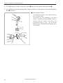
• By changing the tubular round arm mounting width, various sizes can be set.
Note) Change the width, referring to the pin position.
360mm
400mm
600mm
500mm
Note) If two pins cannot be inserted properly, remove one of them.
50
BES-960BC • BES-1260BC
Chapter 2 Preparation of Embroidery Machine
■ Holder base (optional)
w
q
r
i
y
y
e,t
Felt
e
u
Table
y
1mm
r
1mm
t
Attaching the holder base frame
1. Set the table. (Refer to "2-4 Mounting of Table" (Page 33) for details.)
2. Mount the frame connecting plate R w on the X-axis feed frame q, using six bolts, washers,
and nuts.
3. Insert the frame connecting plate y into the holder base frame L e, holder base frame C r,
and holder base frame R t, using bolts and washers.
4. From the front, put the holder base frame C assembly r under the frame connecting plate R
w and fix it using four bolts.
5. Check that the clearance between the table and the mounted holder base frame C assembly
r is even when viewed from the machine front.
[Adjustment]
Loosen three bolts of the F table support F y and move it in the direction of the arrow for adjustment.
BES-960BC • BES-1260BC
51
Chapter 2 Preparation of Embroidery Machine
6. Check that the clearance between the Y-axis cover u and the mounted holder base frames L
e and R t is even when viewed from the right and left sides.
[Adjustment]
Loosen the right and left bolts of the F table guide U i and move it in the direction of arrow for
adjustment.
7. Tighten each bolt securely after adjustment is finished.
Attaching the holder base
1. Mount the holder base mounting frame e on the X-axis feed frame q and holder base frame
C w, using three clamp screws.
2. When the mounting pitch of the holder base is 370 mm, mount the holder base horizontally to
the holder base mounting frames e using the thumb bolts r.
q
r
e
w
52
BES-960BC • BES-1260BC
Chapter 2 Preparation of Embroidery Machine
3. When the mounting pitch of the holder base is 550 mm, mount the holder base vertically to
the X-axis feed frame q and holder base frame C w using the thumb bolts r.
r
q
r
w
BES-960BC • BES-1260BC
53
Chapter 2 Preparation of Embroidery Machine
■ Sash frame (optional)
w
q
q
e
r
y
t
t
y
e
e
Attaching the sash frame
1. Set the table. (Refer to "2-4 Mounting of Table" (Page 33) for details.)
2. Mount two vertical sash frames q on the holder base frames L and R, and two horizontal
sash frames w on the X-axis feed frame e and the holder base frame C r, using the screws.
3. Set the material. Then, set 16 clips 290 y horizontally in two sides and 4 clips 220 y vertically
on the right and left sides.
54
BES-960BC • BES-1260BC
Chapter 2 Preparation of Embroidery Machine
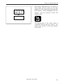
3-5 Bed Retract
When embroidery within the maximum area by mounting the tubular square hoop, there is a
possibility that the hoop interferes with the bed. Retract the bed of several machine heads to
avoid interference.
Note) The machine heads are numbered 1 ~ 6 from the right side.
q
e
w
No.6
No.4
No.2
r
1. Loosen two bolts w that secure the bed support q, and move the bolts w to the right and
left.
Note)
• The bed is secured by two bolts and supported at three places.
• When loosening the bolts, support the bed by hand.
2. Lower the machine bed e slowly until it comes into contact with the leg.
3. Tighten the bolts w again.
BES-960BC • BES-1260BC
55
Chapter 2 Preparation of Embroidery Machine
4. Set the needle bar case at the needle bar No. 1. Remove the presser foot r from the retracted
machine bed.
Note)
• The head of the retracted bed is stopped.
• When removing the presser foot, align the pulley indication mark 3 first.
• To operate the machine in retract position, set the bed in contact with the legs.
Resetting of bed retract
1. Move the machine bed e little by little until it comes into contact with the bed support q.
2. Loosen two bolts w and insert the bed into the right and left directions, then tighten the bolts
securely again.
3. Mount the presser foot for the reset bed e.
(Refer to "Chapter 10. Standard Adjustment" for mounting the presser foot.)
56
BES-960BC • BES-1260BC
Chapter 2 Preparation of Embroidery Machine
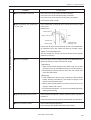
3-6 Adjustment of Thread Tension
■ Adjustment of upper thread
Adjust upper thread tension to 0.7~1.3N (70~130
gf) when the thread is pulled at the needle bar
thread guide.
0.7~1.3N
(70~130gf)
* Correct adjustment
Upper stitch
width
Turn the upper thread tension dial so that the
needle thread can be pulled to the back of the
material and that the lower stitch width will be
about 1/3 of the upper stitch width.
Upper
thread
Lower
thread
Lower
stitch
width
■ Adjustment of tension spring
q
w
e
6~8mm
0.07~0.12N
(7~12gf)
1. The tension spring should be adjusted to 6~8 mm in height and 0.07~0.12 N (7~12 gf) in force.
BES-960BC • BES-1260BC
57
Chapter 2 Preparation of Embroidery Machine
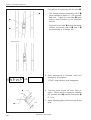
2. For adjusting the height, loosen the screw q and turn the tension spring bracket w.
3. For adjusting the tension spring force, insert a driver tip in the groove of the thread tension
bar e and turn it.
■ Lower thread tension
The standard tension of the lower thread is
0.15~ 0.3N (15~30gf).
This tension may vary depending on the used
thread. In general, press the bobbin case to a
smooth vertical surface and hang the
designated number of coins. Turn the thread
tension screw so that the lower thread will come
out smoothly.
0.15~0.3N
(15~30gf)
To tighten
To loosen
58
BES-960BC • BES-1260BC
Chapter 3
Embroidering Procedures
After installation of machine and setting-up
of the personal computer (PC), start embroidering. This chapter explains about the operation panel on the machine as well as precautions for the actual embroidering process.
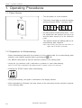
Chapter 3 Embroidering Procedures
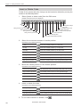
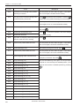
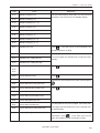
Functions of Operation Panel
Operation Panel
START
Starts embroidering.
Restarts after moving the carriage to embroidering start position by using the jog switch.
Restarts embroidering after a suspension.
STOP
Cancels errors during embroidering.
Exits from the embroidering mode. Hold down switch and press
Suspends embroidering.
Trims thread during suspension.
60
BES-960BC • BES-1260BC
STOP
switch.
Chapter 3 Embroidering Procedures
Checks the embroidering area.
Exits from embroidering mode. Press this switch while holding down
simultaneously to stop embroidering.
STOP
switch
Moves the hoop automatically when embroidering position is out of the embroidering area.
Sets the machine to the inching mode when this switch is pressed during suspension.
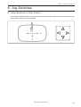
Moves the hoop to software-set position. When this switch is pressed again, the hoop
returns to the previous position.
Moves the needle bar. The needle moves by the diameter every time this switch is pressed.
Moves the hoop.
Step-back or forward is available during suspension, by one stitch every time the switch
is pressed (Use lr switches only.)
Changes the speed range during embroidering (Use ud switches only).
Carries out inching of the hoop when the switch is pressed in the inching mode (
appears on the panel).
■ Canceling errors
When an error message appears, it is canceled by pressing
STOP
switch.
Pressing other switches can stop alarm sound.
When thread breakage or wiper out error has occurred, step-back or forward
switch can be used to cancel errors.
BES-960BC • BES-1260BC
61
Chapter 3 Embroidering Procedures
Switches at Machine Heads
Emergency stop button
Start button
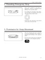
■ Emergency stop button
Stops embroidering operation. When embroidering is stopped,
flashes.
Refer to "Resetting Emergency Stop" (→ page 177) to stop flashing.
■ Start button
Starts embroidering. Holding down this button executes embroidering at a low
speed.
When resuming embroidering after an emergency stop, release emergency stop
before pressing this button. Refer to "Resetting Emergency Stop" (→ page 177)
for details.
Switches on Tension Plate
THREAD SENSOR lamp
HEAD switch
MENDING lamp
MENDING switch
STEP BACK/FWD switch
62
BES-960BC • BES-1260BC
Chapter 3 Embroidering Procedures
■ THREAD SENSOR lamp
When red light is on, thread breakage sensor is functioning. When the light is off,
the sensor is not effective. When the embroidery machine stops due to thread
breakage, the lamp flashes.
■ HEAD switch
When it is set to ON, needle bar on the head moves for embroidering. When it is
set to OFF, the needle bar does not move for embroidering.
■ MENDING lamp
This lamp lights up when the embroidery machine is in the mending mode.
■ MENDING switch
This switch is set to ON to drive or to suspend the machine head during
embroidering for a designated period of time.
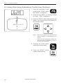
■ STEP BACK/FWD switch
When it is turned to BACK, the machine steps back. When it is turned to FWD,
the machine steps forward. If you keep the switch turned for a while, the machine
will continue stepping even after you let the switch alone. When it is turned to the
opposite side, the machine stops.
During timing adjustment of the rotary hook in the test mode, the rotary hook
slightly rotates to the left/right when this switch is turned to left/right respectively.
Refer to "Adjustment of timing Between Needle and Rotary Hook" (→ page 222)
for further details.
BES-960BC • BES-1260BC
63
Chapter 3 Embroidering Procedures
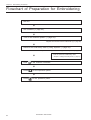
Flowchart of Preparation for Embroidering
Run PC.
▼
Run software (→ page 65).
▼
Turn on the machine power. (→ page 65).
Register the machine name for initial start-up (→ page 65).
▼
Retrieve the embroidery data by using explorer (→ page 66).
"Chapter 4 Selecting and Transferring Embroidery Data" (→ page 67)
Edit the retrieved embroidery data.
▼
Click
"Chapter 5 Editing Embroidery Data" (→ page 91)
of the machine controller.
▼
on the operation panel.
Press
▼
Press
64
START
on the operation panel.
BES-960BC • BES-1260BC
Chapter 3 Embroidering Procedures
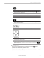
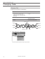
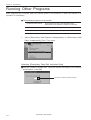
Run the Software
1.
Double-click the shortcut icon "Brother Embroidery Controller" on the
desktop.
The software starts up.
Turn on the Machine Power
1.
Turn on the power to the machine.
2.
The computer screen changes when the machine is turned on.
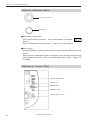
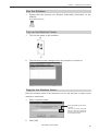
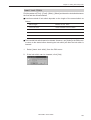
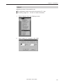
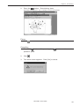
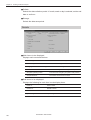
Register the Machine Name
Enter the machine name if the software is run for the first time or when a new
machine is connected.
1.
Enter a machine name.
Select an identifying color for the
machine.
This color is shown on the title
bar for a while when the arrow
pointer is moved to the title bar
of a machine window.
2.
Click [OK].
BES-960BC • BES-1260BC
65
Chapter 3 Embroidering Procedures
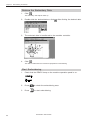
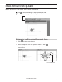
Retrieve the Embroidery Data
1.
Click
.
The embroidery data explorer starts up.
2.
Double-click the desired data or click
after clicking the desired data.
3.
The selected data is transferred to the machine controller.
4.
Click
.
The data is transferred to the machine for preparation of embroidering.
Start Embroidering
66
1.
Check that the READY lamp on the machine operation panel is on.
2.
Press
3.
Press
to check the embroidering area.
START
to start embroidering.
BES-960BC • BES-1260BC
Chapter 4
Selecting and Transferring
Embroidery Data
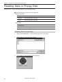
Clicking
on the machine controller brings
up a screen which allows selecting or transference of registered embroidery data. Moving, copying, and deleting of embroidery data
can also be carried out on this screen.
Chapter 4 Selecting and Transferring Embroidery Data
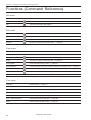
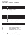
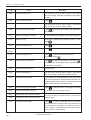
Functions (Command Reference)
File menu
New
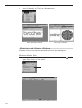
Creates a new directory. (→ page 70)
Exit of Selection
Transfers embroidery data to the machine controller. (→ page 71)
Exit
Exits from embroidery data explorer.
Edit menu
Copy
Copies the selected embroidery data. (→ page 73)
Move
Moves the selected embroidery data to a different directory. (→ page 74)
Delete
Deletes the selected embroidery data. (→ page 75)
Rename
Renames the selected embroidery data. (→ page 76)
View menu
Tool Bar
Displays the tool bar.
Status Bar
Displays the status bar.
List
Displays embroidery data in the text form. (→ page 79)
Image
Displays the image of embroidery data. (→ page 79)
Sort by Name
Sorts embroidery data by name. (→ page 79)
Sort by Stitches
Sorts embroidery data by the number of stitches in ascending order. (→ page 79)
Sort by Colors
Sorts embroidery data by the number of colors in ascending order. (→ page 79)
Sort by Date
Sorts embroidery data by date. (→ page 79)
Refresh
Displays the latest data by updating the screen. (→ page 79)
Tool menu
Find Files
Retrieves files. (→ page 77)
DST/DSB/DSZ → ECS Conversion
Reads DOS format data. (→ page 80)
Barudan FDR → ECS Conversion
Reads non-DOS format data. (→ page 83)
Barudan FMC → ECS Conversion
Reads non-DOS format data. (→ page 83)
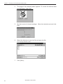
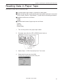
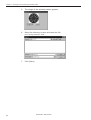
Tape → ECS Conversion
Reads data in paper tape. (→ page 85)
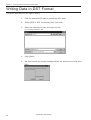
ECS → DST Conversion
Converts ECS data to DST data. (→ page 88)
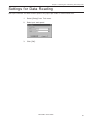
Setup
Defines settings of data reading. (→ page 87)
68
BES-960BC • BES-1260BC
Chapter 4 Selecting and Transferring Embroidery Data
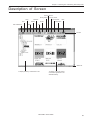
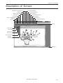
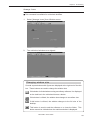
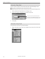
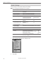
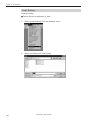
Description of Screen
Sort by Stitches
Sort by Name
Copy
Rename
Exit
Exit of Selection
Sort by Date
Delete
Move
Sort by Colors
Image
Help
Information
List
Tool bar
Status bar
To display hierarchy of directories in PC
To display name and outline
of the data registered in the
selected directory
BES-960BC • BES-1260BC
69
Chapter 4 Selecting and Transferring Embroidery Data
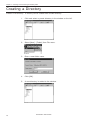
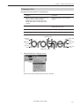
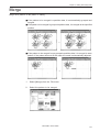
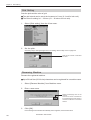
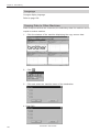
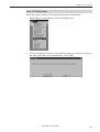
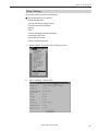
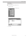
Creating a Directory
Creates a new directory. A directory can be created within another directory.
70
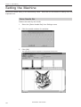
1.
Click and select a parent directory in the window on the left.
2.
Select [New] - [Folder] from File menu.
3.
Enter a new folder name.
4.
Click [OK].
5.
A new directory is added to the window.
BES-960BC • BES-1260BC
Chapter 4 Selecting and Transferring Embroidery Data
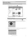
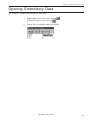
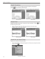
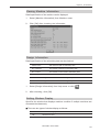
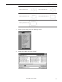
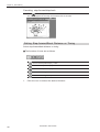
Selecting Data
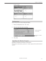
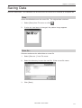
Transfer registered embroidery data to the machine controller or Embroidery data editor.
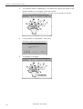
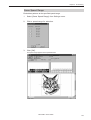
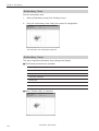
1.
Double-click data, or click data and
.
The explorer exits automatically after transferring the selected data.
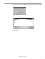
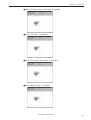
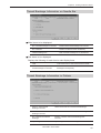
Selecting DST and DSB data
1.
Double click DST or DSB data or click the data and click
.
2.
The pattern image is displayed. To read the selected data, click "OK".
3.
Set the number of feeds for trim. Select the number of settings and click
"OK".
The data is transferred and the explorer ends automatically.
BES-960BC • BES-1260BC
71
Chapter 4 Selecting and Transferring Embroidery Data
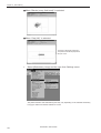
To select data on a network:
1.
Before starting the software, click [START] - [PROGRAM] - [EXPLORER].
2.
Select [Map Network Drive] from Tool menu.
3.
Select the desired drive and enter the path, and click [OK].
4.
Exit from the explorer.
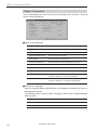
If no image appears:
If no image of embroidery data appears, select "Display Detail" on "Screen" of
the control panel to adjust display color.
Choose one of the following options, then restart PC.
• 256 colors
• High color (16 bits)
Select the display
• Full-color (24 bits)
color using "Color
Pallet".
72
BES-960BC • BES-1260BC
Chapter 4 Selecting and Transferring Embroidery Data
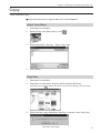
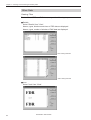
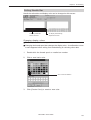
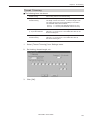
Copy
Copies embroidery data.
■ Select from the menu or drag the data icon to the destination.
Select from Menu
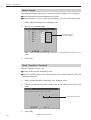
1.
Click data for selection.
2.
Select [Copy] from Edit menu or click
3.
Select destination directory. Name copy data.
4.
Click [Save].
.
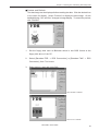
Drag Data
1.
Click data for selection.
2.
Drag data to destination directory while pressing [Ctrl] key.
The pointer turns into
3.
. Release the mouse button when the directory name is inverted.
Check that the copy destination directory is correct, then click [Yes].
BES-960BC • BES-1260BC
73
Chapter 4 Selecting and Transferring Embroidery Data
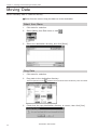
Moving Data
Moves embroidery data to a different directory.
■ Select from the menu or drag the data icon to the destination.
Select from Menu
1.
Click data for selection.
2.
Select [Move] from Edit menu or click
3.
Select the destination directory and click [Save].
.
Drag Data
1.
Click data for selection.
2.
Drag data to the destination directory.
The arrow pointer turns into
3.
74
. Release the mouse button when the directory name is inverted.
Check that the copy destination directory is correct, then click [Yes].
BES-960BC • BES-1260BC
Chapter 4 Selecting and Transferring Embroidery Data
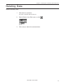
Deleting Data
Deletes embroidery data.
1.
Click data for selection.
The frame of selected data becomes red.
2.
Select [Delete] from Edit menu or click
3.
Click [Yes] to delete the selected data.
BES-960BC • BES-1260BC
.
75
Chapter 4 Selecting and Transferring Embroidery Data
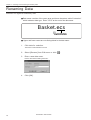
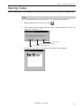
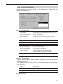
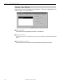
Renaming Data
Renames the registered embroidery data.
■ Data name consists of the name area and three characters called "extension"
which indicates data type. Enter ".ECS" at the end of the data name.
Basket.ecs
拡張子
extension
■ Upper and lower cases are not distinguished in the data name.
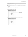
1.
Click data for selection.
The frame of selected data turns red.
2.
Select [Rename] from Edit menu or click
3.
Enter a new data name.
Enter a data name including extension.
4.
76
Click [OK].
BES-960BC • BES-1260BC
.
Chapter 4 Selecting and Transferring Embroidery Data
Finding Data
Retrieves and views embroidery data.
1.
2.
Select [Find Files] from Tool menu.
Enter the file name of embroidery data for search.
Enter the file name correctly.
3.
Click [Find].
BES-960BC • BES-1260BC
77
Chapter 4 Selecting and Transferring Embroidery Data
If the specified embroidery data is found, the data is displayed.
Finding Files With Wildcard Characters
Wildcard characters can be used as a substitute of a single character or
multiple characters. Characters "?" and "*" can be used as wildcard
characters for search.
■ Using "?"
The wildcard character "?" represents any single character. For instance,
if "Basket?.ecs" is entered to the file name box, the search will find any file
name including 'Basket' and a following character. Any number of wild
characters can be used to replace other characters.
■ Using "*"
The wildcard character "*" represents a character or combination of
characters. For instance, if "*.ecs" is entered to the file name box, the
search will find all files with extension "ecs".
78
BES-960BC • BES-1260BC
Chapter 4 Selecting and Transferring Embroidery Data
Adjusting Screen Display
Selects the information type to display on the screen.
■ Tool bar
If it is checked, the tool bar appears.
■ Status bar
If it is checked, the status bar appears.
■ File display format
Choose either option.
List
Displays a list of all embroidery data names and details in the directory in
text format.
Image
Displays a list of all embroidery data names and images in the directory.
■ File sorting order
Choose one of the following options.
Sort by Name
Sorts files by name.
Sort by Stitches
Sorts files by the number of stitches in ascending order.
Sort by Colors
Sorts files by the number of colors in ascending order.
Sort by Date
Sorts files by date.
■ Updating to the latest information
Displays the latest information.
1.
Select [Refresh] from View menu.
BES-960BC • BES-1260BC
79
Chapter 4 Selecting and Transferring Embroidery Data
Reading Data in Floppy Disk
Reads data in a floppy disk and registers it as embroidery data.
■ The following data formats can be registered.
•DOS format data
Tajima
Data with file name "xxxx.DST"
Barudan
Data with file name "xxxx.DSB"
Zanks
Data with file name "xxxx.DSZ"
•Other data
Barudan FDR
Barudan FMC
Reading DOS Format Data
80
1.
Select [DST/DSB/DSZ → ECS Conversion] from Tool menu.
2.
Select data to read and click [Open].
3.
The image of the selected pattern appears.
BES-960BC • BES-1260BC
Chapter 4 Selecting and Transferring Embroidery Data
4.
Set feed counts for thread breakage. Select the desired count and click
[OK].
5.
Select the directory to save and name the file.
Do not change extension ".ECS".
6.
Click [Save].
BES-960BC • BES-1260BC
81
Chapter 4 Selecting and Transferring Embroidery Data
Other Data
Viewing Files
To view files of FDR and FMC data, carry out the following steps:
■ Details
Select "Details" from "View".
Names, types, Numbers and sizes of FDR data are displayed.
Names, types, number of stitches of FMC data are displayed.
When reading FDR data
When reading FMC data
■ Icon
Select "Icon" from "View".
82
BES-960BC • BES-1260BC
Chapter 4 Selecting and Transferring Embroidery Data
■ Preview and Refresh
The data image can be displayed before reading the data. Click the desired icon
or the name for display. Select "Preview" to display the data image. On the
detailed display, "fdr" and "fmc" changes to image display. To cancel the preview,
click "Refresh".
1.
Set the floppy disk such as Barudan which is non-DOS format at the
floppy disk drive of the PC.
2.
Select [Barudan FDR → ECS Conversion] or [Barudan FMC → ECS
Conversion] from Tool menu.
3.
Select data to read and click [OK].
When "Details" is selected
When "Icon" is selected
BES-960BC • BES-1260BC
83
Chapter 4 Selecting and Transferring Embroidery Data
4.
The image of the selected pattern appears. To convert the selected data
into ECS data. Click "OK".
5.
Set feed counts for thread breakage. Select the desired count and click
[OK].
6.
Select the directory to save the file and name the file.
Do not change extension ".ECS".
7.
84
Click [Save].
BES-960BC • BES-1260BC
Chapter 4 Selecting and Transferring Embroidery Data
Reading Data in Paper Tape
Saves data in paper tape as embroidery data.
■ An optional paper taper reader is required for reading data.
■ Before saving any data, check that the paper tape reader (optional) is connected
to PC correctly. Refer to "Tape Reader" (→ page 240) for connecting procedures.
■ Available interfaces are as follows:
• COM1
• COM2
■ Readable data formats of paper tape are as follows:
• Tajima
• Barudan
• Zanks (ZSK)
1.
Turn on the power to the paper tape reader.
2.
Set paper tape after the LED of READ button light up.
Power switch
READ button
Paper tape
3.
Select [Tape → ECS Conversion] from Tool menu.
4.
Select data format and click [OK].
The paper tape reader (optional) starts reading data.
BES-960BC • BES-1260BC
85
Chapter 4 Selecting and Transferring Embroidery Data
5.
The image of the selected pattern appears.
6.
Select the directory to save and name the file.
Do not change extension ".ECS".
7.
86
Click [Save].
BES-960BC • BES-1260BC
Chapter 4 Selecting and Transferring Embroidery Data
Settings for Data Reading
Sets up the interface and data transfer speed of the paper tape reader or external disk drive.
1.
Select [Setup] from Tool menu.
2.
Select port and speed.
3.
Click [OK].
BES-960BC • BES-1260BC
87
Chapter 4 Selecting and Transferring Embroidery Data
Writing Data in DST Format
Convert the ECS data into DST data for saving.
1.
Click the desired ECS data to convert into DST data.
2.
Select [ECS to DST conversion] from Tool menu.
3.
Select the directory to save and name the file.
Do not change extension ".dst".
88
4.
Click [Save].
5.
Set feed counts for thread breakage.Select the desired count and click
[OK].
BES-960BC • BES-1260BC
Chapter 4 Selecting and Transferring Embroidery Data
Viewing Data Information
Detail information of embroidery data can be checked.
■ The following items can be checked.
1.
Pattern name
File name and path of embroidery data
File Version
Version number of the file
No. of stitches
The number of stitches in embroidery data
No. of colors
The number of colors used in embroidery data
Mask Size
Size of masking
Start of Embroidering
Coordinates of embroidering start position
End of Embroidering
Coordinates of embroidering end position
Last modified
Date of last revision of data
Click data for selection.
The frame of the selected data turns red.
2.
Select [Design Information] from Help menu or click
3.
After checking, click [OK].
BES-960BC • BES-1260BC
.
89
Chapter 4 Selecting and Transferring Embroidery Data
90
BES-960BC • BES-1260BC
Chapter 5
Editing Embroidery Data
Clicking
of the machine controller brings
up a screen which allows editing of embroidery data. This screen allows simple processing of embroidery data and display setting of display.
Chapter 5 Editing Embroidery Data
Functions (Command Reference)
File menu
Open
Selects embroidery data. (→ page 95)
Merge
Add other pattern to the pattern in editing. (→ page 115)
Save
Saves the edited embroidery data over the current file. (→ page 117)
Save as
Saves the edited embroidery data as a separate file. (→ page 118)
Print
Prints embroidery data. (→ page 120)
Print Preview
Views printing condition of embroidery data.
Print Setup
Designates printer settings.
Exit Editing
Exits from editing of embroidery data.
Edit menu
Undo
Returns to the previous step. (→ page 103)
Redo
Repeats the step of "Undo". (→ page 103)
Rotate
Rotates the image. (→ page 104)
Horizontal Flip
Flips the image horizontally. (→ page 105)
Vertical Flip
Flips the image vertically. (→ page 105)
Point Symmetry
Rotates the image 180 degrees about the center. (→ page 105)
Repeat
Repeats copying of the image. (→ page 105)
Resize
Resizes the image. (→ page 107)
Delete 0 Stitch
Deletes 0-movement stitches. (→ page 107)
Insert or delete code
Insert or delete the code for trim, pause and color change. (→ page 108)
Insert lock stitch
Insert the lock stitch between the first and the second stitch of "trim" - "feed" - "stitch" - "stitch".(→ page 109)
Change menu
Start
Changes the start position of embroidery data. (→ page 110)
End
Changes the end position of embroidery data. (→ page 111)
Mask
Changes the mask of embroidery data. (→ page 112)
Group
Group the patterns created in "Repeat" into one. (→ page 113)
View menu
Centering
Centers embroidery data. (→ page 96)
Zoom
Zooms in or out. (→ page 96)
Needle Penetration
Displays the needle penetration positions. (→ page 98)
92
BES-960BC • BES-1260BC
Chapter 5 Editing Embroidery Data
Embroidering Start/End
Displays the start/end positions of embroidering. (→ page 98)
Trim and pause
Displays the code insertion position for trim and pause. (→ page 98)
Needle bar and speed range
Displays the setting screen for needle bar and speed range. (→ page 99)
Thread color
Displays the pattern in thread color. (→ page 101)
Tool Bar
Shows/hides the tool bar. (→ page 102)
Status Bar
Shows/hides the status bar. (→ page 102)
BES-960BC • BES-1260BC
93
Chapter 5 Editing Embroidery Data
Description of Screen
Fit to Window Needle bar and
Speed Range
Display Range
Save
Open
Zoom Out
Zoom In
Thread
color
Redo
Undo
Vertical Flip
Horizontal
Flip
Design Information
Point Symmentry
Repeat
Rotate
Print
About This Application
Help
Resize
Tool Bar
Status Bar
94
BES-960BC • BES-1260BC
Chapter 5 Editing Embroidery Data
Opening Embroidery Data
This function is available with embroidery data editor.
1.
Select [Open] from File menu or click
Double-click the data or click the data and
2.
.
.
Click a file for selection and click [Open].
BES-960BC • BES-1260BC
95
Chapter 5 Editing Embroidery Data
Setting Display
Sets the condition of the display screen. Items with check marks to the left are selected.
Centering
Brings the image to the center of the screen.
Before selecting
1.
After selecting
Select [Centering] from View menu.
Zoom
Zooms in/out the pattern.
■ The following four types of zooming are available.
Zoom In
Enlarges the image to 125%.
Zoom Out
Reduces the image to 80%.
Range
Magnifies the range defined by the mouse to the full window size.
Full Window
Displays the whole image to the size of the window.
Zoom In
1.
Select [Zoom] - [Zoom In] from View menu or click
.
Repeats zooming of the image by the number of clicks.
Before selecting
96
BES-960BC • BES-1260BC
After selecting
Chapter 5 Editing Embroidery Data
Zoom Out
1.
Select [Zoom] - [Zoom Out] from View menu or click
.
Repeats zooming of the image by the number of clicks.
Before selecting
After selecting
Range
1.
Select [Zoom] - [Range] from View menu or click
2.
Drag and define the range to zoom in with the mouse.
Before selecting
.
After selecting
Fit to window
1.
Select [Zoom] - [Fit to window] from View menu or click
Before selecting
BES-960BC • BES-1260BC
.
After selecting
97
Chapter 5 Editing Embroidery Data
Needle Penetration
Chooses whether or not the needle pevetration positions are displayed.
1.
Select [Needle Penetration] from View menu.
Before selecting
After selecting
Embroidering Start/End
Displays start and end points as "S" and "E" on the screen respectively.
If points "S" and "E" are identical, "E" has priority over "S".
1.
Select [Embroidering Start/End] from View menu.
Before selecting
After selecting
Trim and pause
Displays the position of the trim code and the pause code.
Trim is displayed by × and pause is displayed by
1.
Select "Trim and pause" from the "View" menu.
→
98
.
BES-960BC • BES-1260BC
Chapter 5 Editing Embroidery Data
Needle Bar and Speed Range
Displays status of the needle bar and speed range.
1.
Select the [Needle bar and speed range] from the View menu or click
Indicates the needle
number and the color.
Indicates the stitching
order and the color.
Pause is set when the
range shows S marking.
.
Indicates the range of
each needle bar.
Change of display color
■ When the color of the embroidering sequence is changed, the color displayed on
the screen is changed. When ending embroidering or reading other data, the
confirmation screen for saving the setting appears.
1.
Double click the desired embroidering sequence to change the color.
2.
Select a new color among the basic colors,then click [OK].
Click color for selection.
3.
Click [Create color] to create a new color.
BES-960BC • BES-1260BC
99
Chapter 5 Editing Embroidery Data
4.
Select a color by clicking on the color chart or by inputting a value.
Drag here to adjust
brightness.
To display data of
the selected color.
5.
Click [Add Color ] to register the selected color.
New colors are
added here.
Changing needle bar allocation
1.
Drag the embroidering sequence on the needle bar number.
Dragged embroidering sequence
100
BES-960BC • BES-1260BC
Chapter 5 Editing Embroidery Data
Setting the range
1.
Double click the desired needle bar range to change.
2.
Click the desired range.
Click here to put a check
mark for pause before
starting the designated
embroidering sequence.
3.
Click [OK].
Thread Color
The embroidery data is displayed in thread color.
■ This functions is available only when the embroidery data edit is started from the
machine controller.
1.
Select [Thread color] from the View menu or click
Before selecting
BES-960BC • BES-1260BC
.
After selecting
101
Chapter 5 Editing Embroidery Data
Tool bar
Shows/hides the tool bar. The tool bar contains icons with the same functions as
the menu.
1.
Select [Tool Bar] from View menu.
Before selecting
After selecting
Status Bar
Shows/hides the tool status. The status bar provides information on the current
status and advice for operation.
1.
Select [Status Bar] from View menu.
Before selecting
102
BES-960BC • BES-1260BC
After selecting
Chapter 5 Editing Embroidery Data
Back to Previous Status
Undo
Makes the edit or change invalid. The screen returns to the state before the change.
■ The screen can return to 3 steps maximum.
1.
Select [Undo] from the Edit menu or click
.
Redo
Repeats the canceled step of "Undo".
■ The screen can return to 3 steps maximum.
1.
Select [Redo] from the Edit menu or click
BES-960BC • BES-1260BC
.
103
Chapter 5 Editing Embroidery Data
Editing
Rotate
→ ■ Available range of rotation is -359 to 359 degrees.
■ When the patterns to be repeated are grouped, the whole pattern rotates. When
they are not grouped, each pattern rotates in each hoop.
When the patterns are grouped
1.
2.
When the patterns are not grouped
Select [Rotate] from View menu or click
.
Select angle.
If [Free] is selected, specify the angle.
To select angle.
Click here to increase/decrease
the value.
The value can be directly entered.
3.
104
Click [OK].
BES-960BC • BES-1260BC
Chapter 5 Editing Embroidery Data
Horizontal Flip
Flips the image horizontally.
→
1.
Select [Horizontal Flip] from Edit menu or click
.
Vertical Flip
Flips the image vertically.
→
1.
Select [Vertical Flip] from Edit menu or click
.
Point Symmetry
Flips the image 180 degrees to the center position of the image.
→
1.
Select [Point Symmetry] from Edit menu or click
.
Repeat
Repeats copying of the image by the specified number.
→
BES-960BC • BES-1260BC
105
Chapter 5 Editing Embroidery Data
■ The number for repetition is 1 to 100 for both vertical (Row) and horizontal
(Column) directions.
■ The unit for repetition can be set in inches. To use the inch unit, set the length to
[inch] on the [Configuration] of Tool menu of the machine controller. (→ page 141)
■ The pattern connection can be set in "Direction" as follows:
From top left,alternating directions
From top left,left to right direction
From bottom left,alternating directions
From bottom left,left to right direction
1.
Select [Repeat] from Edit menu or click
2.
Specify the number, interval and direction of repetition.
Repeat count in the
longitudinal direction
Repeat count in the
lateral direction
.
The value can be directly entered.
Click here to increase/decrease the value.
Select the direction of repetition.
Select the reference position for
spacing.
All patterns created in repetition are grouped as a single pattern.
Longitudinal distance (Unit: 0.1 mm or 0.01")
Lateral distance (Unit: 0.1 mm or 0.01")
3.
106
Click [OK].
BES-960BC • BES-1260BC
Chapter 5 Editing Embroidery Data
Resize
Resizes the image.
→
→
■ Available range of resizing is 50 to 200%.
■ Resizing changes the thread density along with the percentage.
1.
Select [Resize] from Edit menu or click
2.
Specify the percentage of resizing.
.
Click here to increase/decrease the value.
The value can be directly entered.
3.
Click [OK].
Delete 0 Stitch
Deletes 0-movement stitches.
1.
Select [Delete 0 Stitch] from Edit menu.
2.
Deleted result is displayed. Click [OK].
BES-960BC • BES-1260BC
107
Chapter 5 Editing Embroidery Data
Insert or Delete Code
Codes of trim, pause and color change can be inserted or deleted by moving the
needle to the desired position.
1.
Select [Insert or delete code] from the Edit menu.
Needle movement tool bar is displayed.
1 step
10 step
100 step
Next (previous) color change point
Next (previous) feed point
Next (previous) trim code
Next (previous) pause code
Insert (delete) change
color code
Insert (delete) pause code
Insert (delete) trim code
Consecutive step forward specified
Step forward specified
Stop
Step backward specified
Consecutive step backward specified
2.
Select the movement method of needle position.
Click either of the following buttons:
3.
1 step
Moves the needle position by 1 step each.
10 step
Moves the needle position by 10 step each.
100 step
Moves the needle position by 100 step each.
Next (previous) color change point
Moves the needle position to the next (previous) color change point.
Next (previous) feed point
Moves the needle position to the next (previous) feed point.
Next (previous) trim code
Moves the needle position to the next (previous) trim code.
Next (previous) pause code
Moves the needle position to the next (previous) pause code.
Move the needle position to the desired position.
Click either of the following buttons:
4.
Consecutive step backward specified
The needle position returns consecutively until the "Stop" button is pressed.
Step backward specified
The needle position returns for the specified length.
Stop
The needle position stops movement.
Step forward specified
The needle position moves forward for the specified length.
Consecutive step forward specified
The needle position moves forward consecutively until the "Stop" button is pressed.
Insert or delete the code.
Click either of the following buttons:
Insert (delete) trim code
Insert (or delete) the trim code at the current needle position.
Insert (delete) pause code
Insert (or delete) the pause code at the current needle position.
Insert (delete) change color code
Insert (or delete) the change color code at the current needle position.
5. To end code insertion or deletion, click
108
BES-960BC • BES-1260BC
.
Chapter 5 Editing Embroidery Data
Insert Lock Stitch
Find the pattern of [Trim] - [Feed] - [Stitch] - [Stitch] and insert the lock stitch between
the first and the second stitches.
■ Insertion method of lock stitch depends on the length of the second stitch as
follows:
Stitch length
Method of lock stitch
1.2 mm or more
Insert 3 stitches of 0.3 mm stitch.
From 0.9 mm to less than 1.2 mm
Insert 2 stitches of 0.3 mm stitch.
From 0.6 mm to less than 0.9 mm
Insert 1 stitch of 0.3 mm stitch.
Less than 0.6 mm
Do not insert the lock stitch.
■ The inserted lock stitch cannot be deleted. However, use [Undo] in the Edit menu
to return to the status before inserting the lock stitch just after the lock stitch is
inserted.
1.
Select [Insert lock stitch] from the Edit menu.
2.
If the lock stitch can be inserted, click [Yes].
BES-960BC • BES-1260BC
109
Chapter 5 Editing Embroidery Data
Changing Data
Changing Start
Changes the start position of embroidering.
Options
Functions
Center, upper left corner, middle left corner,
lower left corner, middle top edge,
middle bottom edge, upper right corner,
middle right corner, or lower right corner
of the mask
Starts embroidering at the specified
position.
Specify using mouse
Starts embroidering at the position
clicked with the mouse.
Cancel
Cancels the specified position.
Middle top edge
Upper left
corner
Upper right
corner
Middle left
corner
Middle right
corner
Lower left
corner
Lower right
corner
Middle bottom edge
1.
Center
Select [Start] from Change menu.
Click the start position if [Specify using mouse] is selected.
110
BES-960BC • BES-1260BC
Chapter 5 Editing Embroidery Data
Changing End
Changes the end position of embroidering.
Options
Functions
Center, upper left corner, middle left corner,
lower left corner, middle top edge,
middle bottom edge, upper right corner,
middle right corner, or lower right corner
of mask.
Ends embroidering at the specified
position.
Specify using mouse
Ends embroidering at the position
clicked with the mouse.
End at start position
Ends embroidering at the end position.
Cancel
Cancels the specified position.
Middle top edge
Upper left
corner
Upper right
corner
Middle left
corner
Middle right
corner
Lower left
corner
Lower right
corner
Middle bottom edge
1.
Center
Select [End] from Change menu.
Click an end position if [Specify using mouse] is selected.
BES-960BC • BES-1260BC
111
Chapter 5 Editing Embroidery Data
Mask
Changes the mask that represents the periphery of embroidery data. Since the
automatic mask is a rectangle, the pattern within the hoop may be displayed as an
error. In this case, set masking in manual mode.
■ Mask is displayed in a khaki line.
■ There are two types of mask setting as follows:
1.
Automatic
The system measures the image size to create a mask automatically.
Manual
After selecting this mode, specify the mask area using the mouse.
Select [Mask] from Change menu. Select automatic or manual mode.
If [Automatic] is selected, a mask is created automatically.
If [Manual] is selected, drag the area with the mouse to specify the mask.
112
BES-960BC • BES-1260BC
Chapter 5 Editing Embroidery Data
Group
All patterns created in repetition are grouped as a single pattern.
■ The difference between the grouped pattern and the non-grouped pattern is as
follows:
When the patterns are grouped
• Each pattern is displayed in each mask.
• The whole grouped pattern rotates. (→ page 104)
When the patterns are not grouped
• The pattern is displayed only in the original copy source. Figures in other masks
represent the embroidering sequence.
• Each pattern in the mask rotates individually. (→ page 104)
BES-960BC • BES-1260BC
113
Chapter 5 Editing Embroidery Data
Setting Group for Repetition
1.
Select [Repeat] in the Edit menu or click
2.
Click the checkbox of [Group] to put a check mark.
Selecting from Menu
1.
114
Select [Group] from Change menu.
BES-960BC • BES-1260BC
.
Chapter 5 Editing Embroidery Data
Merge
Merge other patterns to the pattern in editing.
■ If the pattern to be merged is repetition data, it is automatically grouped and
merged.
■ If the pattern to be merged is grouped repetition data, it is merged at the specified
position.
→
■ If the pattern to be merged is non-grouped repetition data, it is merged to each
pattern. If the pattern does not fit the mask, the mask is automatically adjusted.
→
1.
Select [Merge] from the File menu.
2.
Select the pattern to be merged.
BES-960BC • BES-1260BC
115
Chapter 5 Editing Embroidery Data
3.
The pattern mask is displayed in a broken line. Move the mask to the
desired position for merging. Click the mouse.
Move the mouse while pressing the shift key. The mask moves horizontally and vertically.
4.
If the position is acceptable, click [Yes].
When [No] is clicked, repeat the steps from 3.
5.
116
The pattern is merged.
BES-960BC • BES-1260BC
Chapter 5 Editing Embroidery Data
Saving Data
Saves the edited data. The edited data can be saved over the current file or renamed as a separate file.
Save
Saves the edited data over the current file. The original data is deleted.
1.
Select [Save] from File menu or click
2.
If the edited data is larger than the mask, choose whether to carry out
automatic masking or not.
.
To cancel saving
To save mask without changing
To set and save mask automatically
3.
If color etc. has been is changed, the pattern image appears.
BES-960BC • BES-1260BC
117
Chapter 5 Editing Embroidery Data
Save As...
Renames and saves the edited data as a new file.
1.
Select [Save as...] from File menu.
2.
Select the directory to save the new file. Enter a new file name.
3.
Click [Save].
4.
If the edited data is larger than the mask, choose whether to carry out
automatic masking or not.
To cancel saving
To save mask without changing
To set and save mask automatically
5.
118
If color etc. has been is changed, the pattern image appears.
BES-960BC • BES-1260BC
Chapter 5 Editing Embroidery Data
Viewing Data Information
Detail information of embroidery data can be checked.
■ The following items can be checked.
No. of stitches
The number of stitches in embroidery data
No. of colors
The number of colors used in embroidery data
Mask Size
Size of masking
Start of Embroidering
Coordinates of embroidering start position
End of Embroidering
Coordinates of embroidering end position
1.
Select [Design Information] from Help menu or click
2.
After checking, click [OK].
BES-960BC • BES-1260BC
.
119
Chapter 5 Editing Embroidery Data
Printing Data
Prints data in editing.
1.
Select [Print] from File menu or click
.
Specify the number of copies and other conditions. Click [OK].
120
BES-960BC • BES-1260BC
Chapter 6 Embroidering
The PC controls the machine operation as
well as settings of the machine. Note that
the menu which appears on the screen depends on whether the power to the machine
is turned on or off.
Chapter 6 Embroidering
Functions (Command Reference)
When the Power to the Machine is Off
File menu
Exit
Exits the machine controller.
View menu
Tool Bar
Displays the tool bar. (→ page 126)
Status bar
Displays the status bar. (→ page 127)
Tool menu
Edit Embroidery Data
Runs the embroidery data editor.
Embroidery Data Explorer
Runs the embroidery data explorer.
Production Report
Runs the production report.
Upgrade Interface Board
(→ page 127)
Reset Interface Board
(→ page 127)
Configuration menu
Communication Port
Sets the communication port between the PC and machine. (→ page 127)
Language
Changes display language. (→ page 128)
When the Power to the Machine is On
Machine menu
Save
The machine data is overwritten for saving. (→ page 171)
Save As
The machine data is saved as a different name. (→ page 171)
Minimize Window Size
Minimizes the size of display screen on the machine. (→ page 138)
Rename Machine
Renames the machine. (→ page 136)
Machine Information
Displays machine information. (→ page 137)
Exit
Exits from the machine controller.
122
BES-960BC • BES-1260BC
Chapter 6 Embroidering
Operation menu
Start Sending
Starts embroidering. (→ page 162)
Stop Machine
Suspends embroidering. (→ page 163)
Cancel Embroidering
Cancels embroidering. (→ page 163)
Home Position
Moves the home position. (→ page 164)
Step F/B
Carries out step-forward or step-back. (→ page 165)
Move Embroidery Position
Moves embroidering position. (→ page 169)
Centering Pattern
Moves pattern to the center. (→ page 170)
Test
Tests the machine. (→ page 173)
View menu
Tool Bar
Displays the tool bar. (→ page 126)
Status Bar
Displays the status bar. (→ page 127)
Zoom In
Zooms in the embroidery data. (→ page 129)
Zoom Out
Zooms out the embroidery data. (→ page 129)
Zoom In Specified Range
Zooms in the specified range. (→ page 130)
Fit to Window
Displays the whole embroidery area. (→ page 130)
Whole Pattern
Displays the whole embroidery data. (→ page 130)
Grid
Displays 1 x 1 cm square grids on the background. (→ page 131)
Hoop
Displays the outline of embroidery hoop. (→ page 131)
Needle Penetration
Displays the position of needle penetration. (→ page 132)
Thread Color
Adjusts the color of the embroidery data to the thread spool. (→ page 132)
Needle Bar and Speed Range
Displays needle bar and speed range. (→ page 132)
Grid Setting
Sets the color and the pitch of grid. (→ page 136)
Tool menu
Language
Changes display language. (→ page 128)
Edit
Allows editing of embroidery data.
Embroidery Data Explorer
Allows selection of embroidery data. (→ page 174)
Production Report
Creates production report. (→ page 174)
Run Embroidery Data Editor independently
Runs the embroidery data editor. (→ page 174)
Run Embroidery Data Explorer independently
Runs the embroidery data explorer. (→ page 174)
Copy to Another Machine
Copies embroidery data to other machines. (→ page 140)
Configuration
Sets configuration for embroidering. (→ page 141)
Version Upgrades
Upgrades the version of the machine parts. (→ page 141)
BES-960BC • BES-1260BC
123
Chapter 6 Embroidering
Settings menu
Same Needle Bar
Uses the same needle bar for all embroidering. (→ page 142)
Same Speed Range
Sets the head. (→ page 143)
Speed Range
Defines the speed range. (→ page 144)
Head Operation Suspend
Cancels the head operation which is not halted on the machine side. (→ page 144)
Hoop Feed Position
Sets the hoop feed position. (→ page 145)
Embroidery Area
Sets the area for embroidering. (→ page 146)
Embroidery Hoop
Sets the type of embroidery hoop. (→ page 146)
Thread Trimming
Sets the inching and thread removal amount. (→ page 149)
Boring
Sets boring. (→ page 150)
Thread Breakage Sensor
Sets operation of thread breakage sensor. (→ page 151)
Automatic Step Back
Sets automatic step back count for thread breakage. (→ page 152)
Automatic Hoop Feed
Feeds hoop to the hoop feed position automatically after embroidering. (→ page 152)
End of Embroidery
Sets if the machine returns to the start point after end of embroidery. ( → page 153)
Mending
Sets details of mending. (→ page 154)
Adjust
Sets the adjusting value. (→ page 154)
Default Settings
Resets changes of the machine setting to the default at the factory shipment. (→ page 156)
Show Setting
Shows the contents of settings. (→ page 157)
Load Setting
Loads the setting details. (→ page 158)
Save Setting
Saves the changed setting. (→ page 159)
Load Hoop
Selects the hoop type. (→ page 160)
Window menu
Cascade
Cascades windows. (→ page 137)
Tile
Tiles windows. (→ page 137)
Arrange Icons
Align icons. (→ page 139)
124
BES-960BC • BES-1260BC
Chapter 6 Embroidering
Description of Screen
Needle bar and speed range
Thread color
Needle penetration
Whole pattern
Fit to window
Zoom in specified range
Zoom out
Zoom in
Cancel embroidering
Suspend embroidering
Home position
Step-back/step-forward
Move pattern
Information
About This Application
Help
Tool bar
Open explorer
Open editor
Copy data to
other machine
Start embroidering
Suspend
embroidering
Status bar
BES-960BC • BES-1260BC
125
Chapter 6 Embroidering
Settings before Turning On the Machine
Describes settings available before the machine is turned on.
■ The following items can be set.
• Displaying the tool bar
• Displaying the status bar
• Upgrading the version of interface board (*)
• Resetting the interface board (*)
• Communication port
• Language
(*) Dealer engineers carries out version upgrading and resetting of the interface
board.
Displaying the Tool Bar
Shows/hides the tool bar. The tool bar contains icons with the same functions as
the menu.
■ There are two kinds of tool bars as follows:
1.
Main
Main menu items are displayed on this tool bar.
Step Back
This tool bar appears during step-back/forward.
Select [Tool Bar] from View menu and put the check mark.
Click here again to remove the check mark. Then the tool bar disappears.
126
BES-960BC • BES-1260BC
Chapter 6 Embroidering
Displaying the Status Bar
Shows/hides the status bar. The status bar provides information on the current
status and advice for operation.
1.
Select [Status Bar] from View menu and put the check mark.
Click here again to remove the check mark. Then the status bar disappears.
Upgrading the Version of Interface Board
Upgrades the version of interface board program connected to PC. This function is
protected by a password. A dealer engineer will use this function if required.
Reset Interface Board
Resets the CPU on the interface board connected to PC to give the same effect as
restart.
This function is protected by a password. A dealer engineer will use this function if
required.
Communication Port
Sets communication port between PC and machine.
1.
Select [Communication Port] from Configuration menu.
2.
Select communication port for use.
If the required port name
does not appear, key-in
the name.
3.
Click [OK].
BES-960BC • BES-1260BC
127
Chapter 6 Embroidering
Language
Changes display language.
■ The following three languages are displayed as "Available Languages".
English
Displays English.
Languages system uses
Displays the system language of PC.
Each respective language
Displays the local language.
1.
Select [Language] from Configuration menu (Tool menu when the power
to machine is on).
2.
Select display language among "Available Languages".
Select display language among
"Available Languages".
When "Each respective language" is selected, the list for "Available Languages" may not be
displayed properly.
128
3.
Click [OK].
4.
Exit and rerun the software.
BES-960BC • BES-1260BC
Chapter 6 Embroidering
Settings after Turning Power On
Describes settings available after turning power on to the machine.
Tool Bar
Shows/hides the tool bar. The tool bar contains icons with the same functions as
the menu.
Refer to page 126.
Status Bar
Shows/hides the status bar. The status bar provides information on the current
status and advice for operation.
Refer to page 127.
Zoom In
Enlarges the image to 125%.
1.
Select [Zoom In] from Display menu or click
.
Repeats zooming of the image by the number of clicks.
Before selecting
After selecting
Zoom Out
Reduces the image to 80%.
1.
Select [Zoom Out] from Display menu or click
.
Repeats zooming of the image by the number of clicks.
Before selecting
BES-960BC • BES-1260BC
After selecting
129
Chapter 6 Embroidering
Zoom In Specified Range
Enlarges the range specified with the mouse to the full window size.
1.
Select [Zoom In Specified Range] from Display menu or click
The arrow pointer turns into
2.
.
Drag and specify the range to zoom in with the mouse.
Before selecting
After selecting
Fit to Window
Displays the whole embroidery area.
1.
Select [Fit to Window] from View menu or click
Before selecting
.
After selecting
Whole Pattern
Displays the whole pattern.
1.
Select [Whole Pattern] from View menu or click
Before selecting
130
BES-960BC • BES-1260BC
.
After selecting
.
Chapter 6 Embroidering
Grid
Displays 1 x 1 cm square grids on the background.
1.
Select [Grid] from View menu and put the check mark.
Before selecting
After selecting
Hoop
Displays the outline of embroidery hoop. The type of embroidery hoop can be
changed in [Load Hoop] of Settings menu.
■ Embroidering is allowed within the green guide in the hoop.
1.
Select [Hoop] from the View menu and put a check mark.
If the hoop is not displayed, carry out the step to read the hoop. For details, refer to [Load Hoop]
( page 160).
Before selecting
BES-960BC • BES-1260BC
After selecting
131
Chapter 6 Embroidering
Needle Penetration
Chooses whether or not the needle penetration positions are displayed.
Clicking
also provides the same function.
1.
Select [Needle Penetration] from View menu and put the check mark.
Before selecting
After selecting
Thread Color
Displays the pattern using colors currently set to the needle bar. Clicking
provides the same function.
1.
also
Select [Thread Color] from View menu and put the check mark.
Display color of the image changes.
Before selecting
After selecting
Needle Bar and Speed Range
Displays the needle bar and speed range.
1.
132
Select [Needle Bar and Speed Range] from View menu and put the check
.
mark or click
BES-960BC • BES-1260BC
Chapter 6 Embroidering
Setting Needle Bar
Needle bar allocation and display color can be changed on this screen.
To display needle bar
number and color
To display embroidering
sequence and color
Changing display colors
■ The color of needle bar changes to the actual color.
■ Changing the thread spool also changes the display color. A confirmation screen
to save appears before exiting from embroidering or retrieving other data.
1.
Double-click the thread spool or needle bar number.
2.
Click a new basic color.
Click a color for selection.
3.
Click [Create Color] to create a new color.
BES-960BC • BES-1260BC
133
Chapter 6 Embroidering
4.
Click the color chart or enter values to create a new color.
Drag here to adjust
brightness.
Displays data of the
selected color
5.
Click [Add Color] to register a new color.
To add new colors
Changing needle bar allocation
1.
Drag a thread spool to the desired needle bar number.
This thread spool has been dragged
134
BES-960BC • BES-1260BC
Chapter 6 Embroidering
Setting Ranges
There are two methods for setting ranges.
All ranges are reduced by
one level.
Displays each thread
bar range.
All ranges are increased by
one level.
When "S" is shown, it is under suspension.
Changing all ranges
1.
Click [Up] to increase range. Click [Down] to reduce range.
One clicking changes the range by one level.
Changing individual range
1.
Double-click the range display.
2.
Click a speed range for selection.
Click here to put a check mark for pause before starting
the designated embroidering sequence.
3.
Click [OK].
BES-960BC • BES-1260BC
135
Chapter 6 Embroidering
Grid Setting
Sets the pitch and the color of grid.
■ The grid interval can be set at the increment of 1 mm (0.1 inch for inch unit).
■ The value for setting is 1 - 100 mm (0.1 - 10 inches for inch unit).
1.
Select [Grid setting] from the View menu.
2.
Set the pitch.
Click the [color] to change the grid color. For setting, refer to steps 2 to 5 in page 133.
Click this to increase or decrease
the value.
Renaming Machine
Rename the registered machine.
■ Up to 50 half-size (25 full-size) characters can be registered for a machine name.
1.
Select [Rename Machine] from Machine menu.
2.
Enter a new name.
Select an identifying color for the
machine.
This color is shown on the title bar
for a while when the arrow pointer is
moved to the title bar of a machine
window.
3.
Click [OK].
If the message "The entered name already exists" appears, enter another name.
136
BES-960BC • BES-1260BC
Chapter 6 Embroidering
Viewing Machine Information
Detail specification of the machine can be displayed.
1.
Select [Machine Information] from Machine menu.
2.
Click [OK] after checking the information.
Design Information
Detail specification of the embroidery data can be checked.
Pattern name
File name and path of embroidery data
No. of stitches
The number of stitches in embroidery data
No. of colors
The number of colors used in embroidery data
Mask Size
Size of masking
Start of Embroidering
Coordinates of embroidering start position
End of Embroidering
Coordinates of embroidering end position
1.
Select [Design Information] from Help menu or click
2.
After checking, click [OK].
.
Setting Window Display
Specifies the window that displays machine condition if multiple machines are
connected simultaneously.
■ There are two types of window display as follows:
Cascade
Windows are slightly offset.
Tile
Windows are tiled.
BES-960BC • BES-1260BC
137
Chapter 6 Embroidering
1.
Select [Cascade] or [Tile] from Window menu.
When [Cascade] is selected
When [Tile] is selected
Minimizing and Aligning Windows
Windows on the screen can be minimized to the icon size and aligned.
Minimize Window Size
1.
Select [Minimize Window Size] from Machine menu or click
upper right corner of the screen.
Click here.
2.
138
The window is minimized.
BES-960BC • BES-1260BC
on the
Chapter 6 Embroidering
Arrange Icons
Minimized windows that are scattered can be aligned.
■ This command is available for minimized windows.
1.
Select [Arrange Icons] from Window menu.
2.
The minimized windows are aligned.
Changing window size
Several square buttons with figures are displayed at the right end of the title
bar. These buttons are used to change the window size.
If this button is clicked when running an ordinary software, it is displayed
on the task bar in the minimized size as a button.
If this button is clicked, the window size changes to a medium size.
If this button is clicked, the window changes to the full size of the
desktop.
This button is used to end the software or to close the folder. This
button cannot be clicked when the machine window is displayed.
BES-960BC • BES-1260BC
139
Chapter 6 Embroidering
Language
Changes display language.
Refer to page 128.
Copying Data to Other Machines
When multiple machines are connected, the embroidery data of a machine can be
copied to another machine.
1.
Click the window of the machine displaying the copy source data.
2.
Click
3.
Click and select the machine name of the destination.
.
4. Click [OK].
140
BES-960BC • BES-1260BC
Chapter 6 Embroidering
The data, is copied.
Configuration
Sets the environment of data reading and display.
1.
Select [Configuration] from Tool menu.
2.
Click and select the item for setting.
Select the applicable
power voltage.
Click here to the default
setting.
3.
Click [OK].
Upgrading the Machine Program
Upgrades the programs at each part of the machine.
This function is protected by a password. A dealer engineer will use this function if
required.
BES-960BC • BES-1260BC
141
Chapter 6 Embroidering
Setting the Machine
Performs the detail setting of the embroidering status. Items that can be selected in Setting menu are
explained here.
Same Needle Bar
Patterns are sewn by one needle.
1.
Select the [Same Needle Bar] from Settings menu.
2.
Click the needle number for selection.
3.
Click [OK].
The embroidering sequence appears at all specified needle points.
142
BES-960BC • BES-1260BC
Chapter 6 Embroidering
Same Speed Range
Embroiders patterns at the specified speed range.
1.
Select [Same Speed Range] from Settings menu.
2.
Click a speed range for selection.
3.
Click [OK].
The speed range appears at the specified areas.
BES-960BC • BES-1260BC
143
Chapter 6 Embroidering
Speed Range
Specifies the maximum speeds for respective ranges suitable for the hoop type.
■ Actual embroidering speed depends on the pitch.
■ Before shipment, "1" is set to the highest speed; "6" is set to the lowest speed.
1.
Select [Speed Range] from Settings menu.
2.
Specify the desired range.
Indicates ranges of
the current setting.
When a value exceeding the above ranges is entered, it is automatically set to the min. or max.
speed.
3.
Click [OK].
Head Operation Suspend
Sets the machine head for rest.
■ Setting at the machine head has priority.
■ When the HEAD switch at the machine head is set to ON and then to OFF, the
setting is canceled.
1.
Select [Head Operation Suspend] from Settings menu.
2.
Click the machine head that needs to be at rest and remove the check
mark.
Head operation suspend
3.
144
Click [OK].
BES-960BC • BES-1260BC
Chapter 6 Embroidering
Hoop Feed Position
Set the basic position of the hoop (hoop feed position) for cancellation of
embroidering.
■ The hoop feed position can be set only in the embroidering area surrounded by a
red frame.
1.
Select [Hoop Feed Position] from Settings menu.
2.
Click the point to feed the hoop.
Hood feed position
3.
The gray cross appears and shows the hoop feed position.
BES-960BC • BES-1260BC
145
Chapter 6 Embroidering
Embroidery Area
Sets the embroidery area.
1.
Select [Embroidery Area] from Settings menu.
2.
Drag the embroidery area using the mouse for designation.
The embroidery area is displayed in light blue.
Embroidery Hoop
The type of specified embroidery hoop changes the display.
■ The following selections are available:
Tubular (All)
Tubular (every 2nd head)
Flat (All)
Flat (every 2nd head)
Border (All)
Border (every 2nd head)
Cap (All)
■ When "Tubular (All)" is selected
146
BES-960BC • BES-1260BC
Chapter 6 Embroidering
■ When "Tubular (every 2nd head)" is selected
■ When "Flat (All)" is selected
■ When "Flat (every 2nd head)" is selected
■ When "Border (All)" is selected
BES-960BC • BES-1260BC
147
Chapter 6 Embroidering
■ When "Border (every 2nd head)" is selected
■ When "Cap (All)" is selected
The image is displayed upside down.
The speed is automatically adjusted to
800 rpm or less.
1.
Select [Embroidery Hoop] and the type from Settings menu.
The pattern direction and embroidering area may vary depending on the selected embroidery
hoop type. Make sure that the selection is correct.
148
BES-960BC • BES-1260BC
Chapter 6 Embroidering
Thread Trimming
■ The following items can be set:
Enable inching
Sets inching motion for thread trimming.
Hoop movement after
thread trimming
Sets the needle penetration length for trimming.
The length can be set in inches. To set the length in inch
unit, select [Inch] from the [Configuration] of Tool menu.
The available values are as follows:
For mm 0 - 100 mm (The standard value is 15 mm.)
For inch 0 - 3.9 inch (The standard value is 0.6 inch.)
Thread length
(1-10) for all machines
Sets the overall thread amount through the needle.
Value of 1 to 10 can be set. The smaller the value is, the
shorter the length is.
Thread length after
thread trimming
Sets the overall thread amount through the needle.
Value of 1 to 10 can be set. The smaller the value is,
the shorter the length is.
1.
Select [Thread Trimming] from Settings menu.
2.
Set inching, thread length, etc.
3.
Click [OK].
BES-960BC • BES-1260BC
149
Chapter 6 Embroidering
Boring
Turns on/off the machine boring mode.
■ The following items can be set:
Boring
Sets ON/OFF of boring.
Shift data
Shifts data by 15 mm to needle number 1. The screen display remains unchanged.
■ Boring can be set only for embroidery data which is prepared for boring. Make
sure that the data is correct before embroidering.
■ Install the following optional parts on the machine before embroidering.
• Boring knife
• Needle plate for boring
■ If the embroidery data for boring is zoomed in or out, or is rotated, embroidering
may not be correctly carried out.
1.
Select [Boring] from Settings menu.
When the boring mode is on, the check mark (√) appears at the top of [Boring] in the menu.
150
2.
Click the setting item to put the check mark.
3.
Click [OK].
BES-960BC • BES-1260BC
Chapter 6 Embroidering
Thread Breakage Sensor
The sensor for thread breakage can be turned ON/OFF or the sensor sensitivity for
each needle bar can be set.
■ The sensitivity can be set within the range of 1 - 100. The smaller the value is,
the higher the sensitivity is.
1.
Select [Thread Breakage Sensor] from Setting menu.
2.
Click the head you want to disable the sensor and remove the check mark (√).
3.
Adjust the sensor sensitivity.
The sensor sensitivity
for each needle bar is
adjusted individually.
All sensor sensitivities
for all needle bars are
adjusted simultaneously.
4.
Click [OK].
BES-960BC • BES-1260BC
151
Chapter 6 Embroidering
Automatic Step Back
Sets the number of stitches for automatic step back if thread breakage occurs.
■ The number of stitches that can be set is from 0 to 255.
■ Additional step-back can be made for sensitivity value of the thread breakage sensor.
1.
Select [Automatic Step Back] from Settings menu.
2.
Enter the number of stitches for automatic step back.
Click here, and the value decreases/increases.
Click here to give additional step-back for the
sensing distance with the thread breakage sensor.
3.
Click [OK].
Automatic Hoop Feed
Sets automatic hoop feed for a thread breakage.
1.
152
Select [Automatic Hoop Feed] from Settings menu and put the check mark
(√).
BES-960BC • BES-1260BC
Chapter 6 Embroidering
End of Embroidery
Sets if the machine returns to the start point after end of embroidery.
1.
Select [End of embroidery] from the Settings menu.
2.
Click the checkbox to put a check mark (V) when the machine returns to
the start point after end of embroidery. Click [OK].
BES-960BC • BES-1260BC
153
Chapter 6 Embroidering
Mending
Sets the details of mending.
■ Items and descriptions are as follows:
154
Automatically rest
breakage error
Error is automatically canceled when a thread
breakage occurs.
Stop the machine at the
mending end position
The needle bar stops at the mending end position.
Stitches before mending
Sets the number of stitches for stopping before
mending. The values for setting are 1 - 10.
When the machine is stopped
Selects how the trimming is made during stopping.
1.
Select [Mending] from the Settings menu.
2.
Click [OK] when the items are set.
BES-960BC • BES-1260BC
Chapter 6 Embroidering
Adjust
Adjustment value of the needle is set.
■ The adjustment value is set at the increment of 0.1 mm.
■ The setting range is 0 - 1.0 mm in X and Y directions.
1.
Select [Adjust] from the Settings menu.
2.
When setting is complete, click [OK].
BES-960BC • BES-1260BC
155
Chapter 6 Embroidering
Default Settings
Resets changes of the machine setting to the default.
■ Items for setting and initialization are as follows:
156
Speed Range
Automatically selects the value suitable for the hoop type.
Head Operation Suspend
Cancels the head operation which is not set for rest on
the machine.
Hoop Feed Position
Returns to the machine home position.
Embroidering Area
Sets the size each for the selected hoop.
Thread Trimming
Inching motion
Thread removal feed length
Thread remaining amount
Yes
15 mm (0.6 inch)
5
Boring
Boring
Data shift
No
No
Thread Breakage Sensor
All sensors are on.
Sensitivity
10
Automatic Step Back
0
Thread Breakage
Sensor Sensitivity
Not affected by the thread breakage sensor sensitivity
Automatic Feed Hoop
No
Return to the start point
Yes
Mending
Automatically rest breakage error
Stop the machine at the mending end position
Stitches before mending
Trim during stop in mending setting
Adjustment
0.0 mm for X direction
0.0 mm for Y direction
1.
Select [Default Settings] from Settings menu.
2.
Click [OK].
BES-960BC • BES-1260BC
Yes
Yes
5 stitches
No
Chapter 6 Embroidering
Show Setting
Shows the setting contents and defaults.
■ The following items are shown:
• Embroidering area
• Thread trimming inching motion
• Thread removal feed length
• Boring
• Shift
• Thread breakage sensor sensitivity
• Automatic step back
• Automatic feed hoop
• Return to the stant point
1.
Select [Show Contents] from Settings menu.
2.
After checking, check [OK].
BES-960BC • BES-1260BC
157
Chapter 6 Embroidering
Load Setting
Load the setting.
■ The set file has an extension of "ecm".
158
1.
Select [Load setting] from the Settings menu.
2.
Select the folder and click [Open].
BES-960BC • BES-1260BC
Chapter 6 Embroidering
Save Setting
Saves the edit settings.
■ Save the setting files with an extension of "ecm".
1.
Change the setting.
2.
Select [Save setting] from the Settings menu.
3.
Select the registration folder and put a file name.
4.
Click [Save].
BES-960BC • BES-1260BC
159
Chapter 6 Embroidering
Load Hoop
Load the optional hoop displayed in "Hoop".
■ The hoop file to be loaded has an extension of "ehp".
■ The types and the shapes of hoop for loading are as follows:
160
ROUND_FRAME21.ehp
ROUND_FRAME25.ehp
SQUARE_FRAME45X23.ehp
SQUARE_FRAME45X27.ehp
SQUARE_FRAME45X32.ehp
SPIDER_NET_FRAME07.ehp
SPIDER_NET_FRAME09.ehp
SPIDER_NET_FRAME12.ehp
SPIDER_NET_FRAME15.ehp
SPIDER_NET_FRAME18.ehp
TUBULAR_FRAME10.ehp
TUBULAR_FRAME13.ehp
TUBULAR_FRAME30X43.ehp
HOLDER_BASE30X43.ehp
HOLDER_BASE30X48.ehp
TUBULAR_ROUND07.ehp
TUBULAR_ROUND09.ehp
TUBULAR_ROUND12.ehp
BES-960BC • BES-1260BC
Chapter 6 Embroidering
TUBULAR_ROUND15.ehp
TUBULAR_ROUND18.ehp
TUBULAR_ROUND24X24.ehp
TUBULAR_ROUND24X30.ehp
TUBULAR_ROUND32X45.ehp
1.
Select [Load hoop] from the Settings menu.
2.
Select the folder and click "Open".
BES-960BC • BES-1260BC
161
Chapter 6 Embroidering
Embroidering
How to start embroidering and operation after the start are explained here.
Starting Embroidering
■ The following screen appears when the edit data is retrieved from the explorer.
To run the embroidery data explorer
To run the embroidery data editor
To copy the current data to other linked machines
To start embroidering
To suspend embroidering
To display the speed and the range
To display the overall number of stitches and the current number
of stitches
The progress of embroidering is displayed on a bar chart.
To display the name of the embroidering data
Click here and the overall speed range increases by one level.
Click here and the overall speed range decreases by one level.
To display the status of the machine.
1.
Click
.
"Hoop" appears at the machine display window.
162
BES-960BC • BES-1260BC
Chapter 6 Embroidering
2.
Press the
button. Embroidering starts.
Embroidery data appears in gray, indicating the embroidering status.
Pause
1.
Click
.
Canceling
1.
Press the
button while pressing the
operation panel.
2.
Click
3.
The check screen appears. Click [Yes] to cancel.
STOP
button on the machine
.
BES-960BC • BES-1260BC
163
Chapter 6 Embroidering
Moving the Home Position
Move the selected machine home position.
1.
164
Select [Home Position] from Operation menu or click
BES-960BC • BES-1260BC
.
Chapter 6 Embroidering
Step-forward/Step-back
Allows step-forward or step-back of stitches without embroidering.
■ Click
to stop embroidering for step-forward/back mode.
■ The special tool bar appears in the step-forward/back mode.
Tool bar for step-back/step-forward
Entering in the Step-forward/Step-back Mode
1.
2.
Click
to stop embroidering.
Select [Step F/B] from the Operation menu or click
.
A cross appears on the screen. The current needle position is the intersection of the vertical and
horizontal lines.
Current needle position
BES-960BC • BES-1260BC
165
Chapter 6 Embroidering
Canceling step-forward/step-back
1.
Click
of the step forward/back tool bar.
The cross disappears and the step forward/back mode is canceled.
Setting Step-forward/Back Distance or Timing
Select step-forward/back distance or timing.
■ The functions of icons are as follows:
Moves forward (backward) by 1 stitch.
Moves forward (backward) by 10 stitches.
Moves forward (backward) by 100 stitches.
Moves to the next (previous) color change.
Moves to the next (previous) feed.
1.
166
Click the icon to select the desired function.
BES-960BC • BES-1260BC
Chapter 6 Embroidering
Stepping Forward/Back
Steps forward/back the stitches actually.
■ The functions of icons are as follows:
Returns to the start position. For repeating patterns, returns to the start position of the current pattern.
Moves backward by the specified distance continuously. Click
to stop movement.
Moves backward by the specified distance.
Click this to stop after clicking
or
.
Moves forward by the specified distance.
Moves forward by the specified distance continuously. Click
to stop movement.
This is selected for repeating patterns. The machine goes to the start position of the next pattern.
Specify the travel length from the embroidery start point.
■ Selection of movement to the start position. The needle moves as follows:
Click the
icon and the needle
moves to the start position of the
current pattern.
→
Click the
icon
and the needle
moves to the start
position of the next
repeating pattern.
BES-960BC • BES-1260BC
167
Chapter 6 Embroidering
1.
Select the icon and move the cross to the desired position for step
forward/back.
Forward
Backward
Specifying the Value
Specify the travel length from the embroidery start point.
.
1.
Click
2.
Input the number of stitches to start embroidery. Click [OK].
Resuming Embroidering
1.
Click
in the tool bar.
The cross disappears. The embroidery status at the step forward/backward position of the
stitches is displayed.
Forward
2.
Click
Backward
.
It is ready to resume embroidering and "Hoop" appears at the machine display window.
3.
168
Press
START
on the machine.
BES-960BC • BES-1260BC
Chapter 6 Embroidering
Moving Embroidery Position
Changes the position of embroidery data.
■ Movement is allowed only in the embroidering area (within the red frame).
Embroidering area
1.
Select [Move Embroidery Position] from Operation menu or click
2.
The pointer turns into
.
. Drag the embroidery data.
The mouse arrow becomes + while dragging.
BES-960BC • BES-1260BC
169
Chapter 6 Embroidering
Centering Pattern
Moves the pattern to the machine home position.
170
1.
Select [Move Pattern] from Operation menu.
2.
The pattern is moved.
BES-960BC • BES-1260BC
Chapter 6 Embroidering
Saving Data
Saves the edited data. The edited data can be saved over the current file or renamed as a separate file.
Save
Saves the edited data over the current file. The original data is deleted.
1.
Select [Save] from File menu or click
2.
If color etc. has been is changed, the pattern image appears.
.
Save As...
Renames and saves the edited data as a new file.
1.
Select [Save as...] from File menu.
2.
Select the directory to save the new file. Enter a new file name.
3.
Click [Save].
BES-960BC • BES-1260BC
171
Chapter 6 Embroidering
4.
172
If color etc. has been is changed, the pattern image appears.
BES-960BC • BES-1260BC
Chapter 6 Embroidering
Test
Carries out sensor information check, actuator operation test, test for main shaft rotation, etc. for machine
maintenance.
This function is protected by a password. A dealer engineer will use this function if
required.
BES-960BC • BES-1260BC
173
Chapter 6 Embroidering
Running Other Programs
Other programs can be started when the machine power is not turned on or when the machine is in
operation for embroidery.
■ The following programs can be started:
1.
Embroidery data explorer
Allows transfer and copy of the embroidery data.
Data transfer to the machine controller is not allowed.
Embroidery data editor
Allows editing of embroidery data.
Production report
Allows display and print-out of production data, etc.
Select [Embroidery Data Explorer independently] or [Embroidery Data
Editor independently] from Tool menu.
Selecting [Embroidery Data Edit Individual Start]
■ Input the number of needle bars. Input the number according to your machine
specifications. Click [OK].
Click this to increase or decrease the value.
174
BES-960BC • BES-1260BC
Chapter 7 Operation of Machine
Chapter 7 Operation of Machine
1. Operating Procedures
1-1 Power Source
• Turn the power on to the machine.
• The power lamp lights up and the display
window indicates "BES-", and then "960".
• An alarm buzzer sounds three times. Then
the needle bar and presser foot move up
and the frame moves up to the reference
point.
The machine enters the waiting state for an
embroidering data selection.
Note) When turning the power off and back it on
again, wait for at least 10 seconds.
1-2 Preparation for Embroidering
• Select embroidering data while the machine is in the waiting state for an embroidering data
selection, and transmit required data by pressing the
icon.
• The READY lamp lights up and the machine is placed in the waiting state.
• Using the jog switches (udlr), determine a position to start embroidering.
Note) An error code is displayed in the display window if a pattern comes out of the hoop.
• Pressing the START switch starts embroidering.
START
* During embroidering, the speed is indicated in the display window.
• After embroidering is finished, the hoop returns to the start point and the machine is placed
in the stand-by state.
176
BES-960BC • BES-1260BC
Chapter 7 Operation of Machine
2. Resetting Emergency Stop
• When either emergency stop button is
depressed, "STOP" is displayed while
blinking on the operation panel.
• For resetting the emergency stop button,
turn the button in the direction of the arrow.
The button pops up and is reset.
• Check that both emergency stop buttons
on the right and left are reset.
3. Permission for Hoop Movement
• When the computer has given a command
to move the embroidery hoop, "HOOP" is
displayed while blinking on the operation
panel.
• Press the check switch and the embroidery
hoop moves to the designated position.
BES-960BC • BES-1260BC
177
Chapter 7 Operation of Machine
4. Measures against Thread Breakage
4-1 Remedies
1. If embroidering is suspended due to thread
breakage, the THREAD SENSOR lamp of
the machine head with a thread breakage
blinks.
2. Correct the broken thread and pass it
through again.
* Refer to "Chapter 2, 3-1 Upper Threading" for details.
3. Press the STOP switch or press the STEP
BACK/FWD switch in order to reset the
alarm.
STOP
4. Return the hoop to a position where thread
breakage occurred by pressing the STEP
BACK switch.
THREAD
SENSOR lamp
HEAD switch
or
MENDING
lamp
MENDING
switch
STEP BACK/
FWD switch
Note) When the switch is turned for 20 stitches or
more, the machine continues operation without holding the switch. To stop the machine,
turn the switch to the opposite side.
5. Press the START switch on the operation
panel or the start switch located between
the machine heads to resume operation.
or
START
178
BES-960BC • BES-1260BC
Chapter 7 Operation of Machine
4-2 Mending
The machine head whose MENDING lamp is lit performs embroidering by the preset number
stitches. When it is completed, all the machine heads start normal embroidering operation.
• The MENDING lamps except for the
machine head whose needle thread has
been broken are turned off.
• At this time, the machine head, whose
MENDING lamp is on, performs resewing
from the step-back position while the other
machine heads (with MENDING lamps off)
are stopped. When resewing is completed,
the other machine heads (except those
halted or with bed retracted) also start
embroidering.
■ Manual operation
The mending start and end positions can be set for each machine head using the MENDING switch on
the tension plate.
The MENDING lamp is lit when the
MENDING switch of each machine head is
flipped up during standby. Resewing from
the step-back position to this position can
be executed.
* When the MENDING switch is flipped up
while the MENDING lamp is off, the lamp is
turned on; when the MENDING switch is
flipped up again while the MENDING lamp
is lit, the lamp is turned off.
Note) The mending end position cannot be set for
each machine head.
When all MENDING lamps are turned on, the
mending end position will be set to the position where one of the lamps is turned off first.
Note) To cancel the mending end position, turn all
the MENDING lamps are turned on (except for
halted machine heads) .
BES-960BC • BES-1260BC
179
Chapter 7 Operation of Machine
No.1 Stitch
Stand by
position A
No.2 Stitch
No.3 Stitch
No.3
Mending LED is off.
No.1 Stitch
B
No.2 Stitch
No.3 Stitch
1. Turn off the MENDING lamp No. 3 at the
standby position A.
(The position A should be the mending end
position.)
2. Press the jog l switch or
to move it
backward.
Turn off the MENDING lamp No. 2 at the
position B.
(The position B does not become the end
position; the position A remains the end
position.)
Note) When the MENDING switch of the machine
head whose lamp is off is pressed:
• The MENDING lamp of the machine head is
lit, and mending is executed for the machine head.
Mending LED
Note) When the MENDING switch of the machine
head whose lamp is on is pressed:
• The MENDING lamp of the machine head
goes off and mending is not excuted for the
machine head.
Stand by
position A
180
BES-960BC • BES-1260BC
Chapter 7 Operation of Machine
5. Jog Embroidering
• Jog embroidering can be used for
preventing the thread from slipping from
the needle at the start of embroidering.
• Jog embroidering can be executed as long
as the start switch at the machine head is
held down.
Note) Never apply a tape on the switch to keep jog
operation for a long time. Doing so may cause
damage to the machine.
6. Hoop Feed Position
• In order to ease mounting and dismounting of the embroidery hoop, another needle position
can be set as a hoop feed position in the movable area additionally to the current needle
position. (The hoop feed position should be set by the personal computer.)
• In order to ease material attachment while operation is suspended, the hoop can be moved
to the feed position at any time by the hoop feed switch.
• The hoop can also be moved to the feed position automatically after embroidering is finished.
Refer to "Automatic Hoop Feed" on Page 152 for details.
BES-960BC • BES-1260BC
181
Chapter 7 Operation of Machine
7. Area Check
7-1 External Tracing
• If the check switch is pressed in other
cases than "area over", the rectangular
outline of the pattern is traced.
Embroidering
start position
7-2 Automatic Hoop Movement in Area
0.1mm
(Example)
0.1mm
Embroidering area
• If "area over" is displayed, press the check switch. The hoop automatically moves inside the
embroidering area, where the pattern is set, at the nearest position.
Note) After finishing the movement inside the area by this function, execute external tracing. Then, check that
the needle and the presser foot do not interfere with the hoop before starting embroidering.
Embroidering area
If the pattern is not held in the embroidering area as shown below, the hoop cannot move into the area.
Enlarge the embroidering area on the personal computer.
182
BES-960BC • BES-1260BC
Chapter 7 Operation of Machine
8. Jog Switches
8-1 Hoop Movement to Start Position
The hoop immediately after the embroidering mode becomes valid can be moved so that the
start position can be set as required.
BES-960BC • BES-1260BC
183
Chapter 7 Operation of Machine
8-2 Inching Mode during Embroidering (Forcible Hoop Movement)
1. Press the jog switch u while
pressing the "STOP" switch
and "AJST" is displayed.
2. Press the jog switch r to forcibly change
the hoop. "JOG" is displayed.
3. Press the "START" switch and press the jog
switch. The hoop moves to the direction of
the pressed switch.
START
Note)
• Note that the forcible hoop movement will
produce deviation of embroidering by the
amount.
• If the hoop and material are deviated from
each other during embroidering, correct it
by using the jog switches.
4. Pressing the STOP switch
resets the inching mode.
STOP
5. Press the START switch
restarts embroidering.
START
184
BES-960BC • BES-1260BC
Chapter 8
Creating Production Report
Records and controls the machine operation.
The production report can be created based
on this data. Detailed information of production report allows efficient embroidering control.
Chapter 8 Creating Production Report
Functions (Command Reference)
File menu
Open Report File
Opens the report file. (→ page 188)
Save As CSV
Saves the current report data in CSV format. (→ page 201)
Print
Prints the report. (→ page 202)
Print Preview
Displays the print preview on the screen.
Page Setup
Displays the setting screen for printing. (→ page 202)
Exit from Production Report
Exits from the production report.
Edit menu
Copy
Copies the selected area to the clipboard. (→ page 203)
Select All
Selects all report data.
View menu
Details
Displays detail data. (→ page 196)
Thread Breakage Information on Needle Bar
Displays the thread breakage information for each machine needle. (→ page 197)
Thread Breakage information in pattern
Displays the thread breakage information for each pattern. (→ page 197)
Output information
Displays the production output of each machine. (→ page 198)
Total output information
Displays the total production output. (→ page 199)
Top page
Displays the top page.
Previous page
Displays the previous page.
Next page
Displays the next page.
Last page
Displays the last page.
Tool Bar
Displays the tool bar.
Status Bar
Displays the status bar.
Settings menu
Items to be displayed
Sets the display item. (→ page 195)
Delete report file (s)
Deletes the report file. (→ page 204)
186
BES-960BC • BES-1260BC
Chapter 8 Creating Production Report
Description of Screen
Thread Breakage for Each Needle Bar
Detailed Data
Save as CSV
Open report file
Thread Breakage for Each Pattern
Total Output
Output
Copy
About This Application
Print
Help
Status bar
BES-960BC • BES-1260BC
187
Chapter 8 Creating Production Report
Displaying Report
Displays the machine operation status in the form of report.
■ The following reports can be displayed:
Details
Displays detail data while the machine is in operation.
Thread Breakage
information on Needle Bar
Displays the thread breakage information for each machine.
Thread Breakage
information in Pattern
Displays the thread breakage information for each pattern.
Output information
Displays production output or efficiency of the selected machine.
Total output information
Displays production output or efficiency of multiple machines.
■ Items to be displayed in each report can be set. For details, refer to "Setting
Display Items" (→ page 195).
1.
Select the desired report from View menu or on the tool bar.
2.
Select [Open] from File menu or click
3.
Select the applicable machine.
.
Click here to select the
machine for detail data,
thread breakage and
output information.
Click here to select the
machine for total output
information. Click here
again to cancel the
selection.
4.
Click [OK].
5.
Specify the period to read.
For more information, refer to "General" in "Setting Display Items" on page 195.
6.
Click [OK].
The report appears.
188
BES-960BC • BES-1260BC
Chapter 8 Creating Production Report
Display Example of Details
Displays the machine information chronologically that are collected within the
specified period.
The following information is indicated under the "Reason" column:
Display
Contents
Power ON
The machine power was turned on.
If the computer is turned on after the machine power has
been on, it shows the time when the computer recognized
the machine.
Power OFF
The machine power was turned off.
If the computer is turned off before the machine power, it
shows the time when the computer program quit.
Load design (*)
The name of the loaded pattern and the number of stitches
are indicated. This is also recorded when embroidering was
started after the power was turned off and back on.
Embroidering started
Embroidering was started.
Embroidering completed
Embroidering was completed.
Embroidering canceled
Embroidering was canceled.
The information on the pattern is deleted from the record.
Color change (*)
The needle bar number and the number of stitches after
color change are indicated.
Suspended (*)
The machine operation was suspended by the operator.
Stoppage due to thread
breakage (*)
A thread breakage occurred. The head number,
the needle bar number and the speed range are indicated.
Error (*)
The machine was stopped due to an error.
Embroidering restarted (*)
Embroidering was restarted after a suspension, a thread
breakage, or an error.
The items marked with "*" can be shown or hidden on the " Setting items to be
displayed" screen.
BES-960BC • BES-1260BC
189
Chapter 8 Creating Production Report
Display Example of Thread Breakage Information on Needle Bar
Displays the information on thread breakage occurrences with head numbers and
needle bar numbers. Three needle bars with frequent thread breakage are
indicated.
Display
Contents
No. of times thread is
trimmed (*)
Number of thread breakage occurrences per needle bar
No. of stitches (*)
Number of stitches embroidered with the needle bar during
the specified period
Thread breakage rate (*)
Thread breakage rate per 10,000 stitches
(10000 x No. of times thread is trimmed) /No. of stitches
Total (*)
Total for all the heads or all the needle bars
Needle bar with frequent thread
breakage occurrence (*)
Three needle bars that have thread breakage frequently,
in the decreasing order of frequency
The items marked with "*" can be shown or hidden on the " Setting items to be
displayed" screen.
190
BES-960BC • BES-1260BC
Chapter 8 Creating Production Report
Display Example of Thread breakage Information in Pattern
Displays thread breakage information for each pattern.
Display
Contents
n th
The pattern was embroidered for the "n"th time.
Pattern name
Name of the pattern that was embroidered
Head No. (*)
Head number where a thread breakage occurred
Needle bar no. (*)
Needle bar number where a thread breakage occurred
n th stitch (*)
The ordinal number of the stitch when a thread breakage occurred
Speed range (*)
Speed range that was effective when a thread breakage occurred
The items marked with "*" can be shown or hidden on the " Setting items to be
displayed" screen.
BES-960BC • BES-1260BC
191
Chapter 8 Creating Production Report
Display Example of Output Information
Displays the production information that are collected during the specified period.
Display
Contents
Total electricity supply time
Total time when the machine was energized within the
specified period
Total embroidering time
Total time when the machine embroidered within the
specified period
Total actual embroidering time
Total actual time when the machine embroidered
within the specified period
Excluded time
Total time of intermission and maintenance for the number
of days in the specified period
Electricity supply efficiency
Electricity supply efficiency by calculating below:
(Total electricity supply time - excluded time) /
total electricity supply time
Embroidering efficiency period
Ratio of the actual embroidering time to the total
embroidering time
Total actual embroidering time / total embroidering time
Number
The pattern embroidered during the specified period is numbered.
Pattern name
Name of the pattern
No. of stitches in pattern
Number of stitches in the pattern
Total stitches (*)
Total number of stitches by repeating embroidering
No. of stitches in pattern X No. of times embroidered
No. of colors in pattern (*)
Number of colors in the pattern
No. of times embroidered (*)
Number of embroidering repeated
No. of workpieces embroidered (*)
Number of finished sheets by one embroidering cycle
Total no. of heads which
are stopped
Total number of the heads at rest for one embroidering
cycle
Embroidering time (*)
Time from embroidering start to the end for the pattern
Embroidering speed (*)
Average embroidering speed in the embroidering time
(the number of stitches per minute)
Total stitches/embroidering time
Actual embroidering time (*)
Actual embroidering time excluding the stop time by thread
breakage, suspension and errors from the embroidering time
Actual embroidering speed (*)
Average embroidering speed in the actual embroidering
time (the number of stitches per minute)
Total stitches/actual embroidering time
Embroidering efficiency (*)
Ratio of the actual embroidering time to the embroidering time
Actual embroidering time / embroidering time
Time stopped (*)
Total of stop time during embroidering
Reason for stoppage (*)
Reasons for stoppage are indicated. Refer to the next page.
The items marked with "*" can be shown or hidden on the " Setting items to be
displayed" screen.
192
BES-960BC • BES-1260BC
Chapter 8 Creating Production Report
Details of reason for stoppage
Suspended
Frequency and total time stopped by the operator
Stoppage due to
thread breakage
Frequency and total time stopped by thread breakage
Error
Frequency and total time stopped by errors
BES-960BC • BES-1260BC
193
Chapter 8 Creating Production Report
Display Example of Total Output Information
Displays the output information per pattern on multiple machines that are selected.
Display
Contents
Number
The pattern embroidered during the specified period is numbered.
Pattern name
Name of the pattern
No. of stitches in pattern
Number of stitches in the pattern
Total stitches (*)
Total number of stitches by repeating embroidering
No. of stitches in pattern X No. of times embroidered
No. of colors in pattern (*)
Number of colors in the pattern
No. of times embroidered (*)
Number of embroidering repeated
No. of workpieces embroidered (*)
Number of finished sheets by one embroidering cycle
Total no. of heads which
are stopped
Total number of the heads at rest for one embroidering
cycle
Embroidering time (*)
Time from embroidering start to the end for the pattern
Embroidering speed (*)
Average embroidering speed in the embroidering time
(the number of stitches per minute)
Total stitches/embroidering time
Actual embroidering time (*)
Actual embroidering time excluding the stop time by thread
breakage, suspension and errors from the embroidering time
Actual embroidering speed (*)
Average embroidering speed in the actual embroidering
time (the number of stitches per minute)
Total stitches/actual embroidering time
Embroidering efficiency (*)
Ratio of the actual embroidering time to the embroidering time
Actual embroidering time / embroidering time
Time stopped (*)
Total of stop time during embroidering
Reason for stoppage (*)
Reasons for stoppage are indicated. Refer to the next page.
The items marked with "*" can be shown or hidden on the " Setting items to be
displayed" screen.
194
BES-960BC • BES-1260BC
Chapter 8 Creating Production Report
Setting Display Items
Sets display items for each production report.
■ The following tab windows can be set:
General
Items related to the overall display of the output report.
Details
Items related to detail data.
Thread Breakage
information on Needle Bar
Items related to thread breakage for each needle bar.
Thread Breakage
information in Pattern
Items related to thread breakage for each pattern.
Output information
Items related to output information.
Total output information
Item related to total output information.
Recess time
setting
Items not included in the efficiency calculation for
output information and total output information.
1.
Select [Items to be displayed] from Settings menu.
2.
"Setting items to be displayed" screen appears.
Click the tab on the screen and the tab window for the items appears.
Tab
General
BES-960BC • BES-1260BC
195
Chapter 8 Creating Production Report
■ Collate
Selects the data collection period. If month, week or day is selected, set the end
date or end hour.
■ Storage
Selects the data save period.
Details
■ Main items to be displayed
Displays each event and the time.
Load design
Transfer time of embroidery data
Color change
Time of color change
Stoppage due to thread breakage
Time of thread breakage
Restart
Time of resuming embroidering after suspension
Stop after pressing button
Time when the emergency stop button was pressed
Suspended Error
Time when an error has occurred
■ Sub items to be displayed
Displays the following for each item in main display items.
196
Head no.
Head number
Needle no.
Needle number
No. of stitches
Number of stitches
Speed range
Speed range
BES-960BC • BES-1260BC
Chapter 8 Creating Production Report
Thread Breakage Information on Needle Bar
■ Main items to be displayed
No. of thread breakage occurrences
Number that thread breakage has occurred
No. of stitches
Number of stitches used in embroidery
Thread breakage rate
Rate of thread breakage for 10,000 stitches
■ Sub items to be displayed
Displays the following for each item in main display items.
Total
Total of the item for each head and each needle
Needle Bar with frequent
thread breakage occurrences
Data of three needles that have caused thread
breakage most frequently
Thread Breakage Information in Pattern
Head no. where thread
breakage occurred
Head number that has caused thread breakage
Needle bar no. where thread
breakage occurred
Needle number that has caused thread breakage
No. of stitches until thread
breakage
Number of stitches until thread breakage has
occurred
Speed range
Speed range when thread breakage has occurred
BES-960BC • BES-1260BC
197
Chapter 8 Creating Production Report
Output Information
Time is calculated to the unit of second, but the display unit is in minute. This may
result in minor differences.
■ Items to be displayed
Total stitches
The total number of embroidery stitches from start to end
No. of times embroidered
Number of embroidering
Embroidering time
The total time from start to end spent for embroidery
Actual embroidering time
Time spent for embroidering
Time stopped
Time not spent for embroidering
Embroidering efficiency
Actual embroidery time/Embroidering time (in %)
Reason for stoppage
Event that caused a stop
No. of colors in pattern
Number of colors in pattern
No. of workpieces embroidered
Number of sheets embroidered.
Embroidering speed
Number of total stitches/Embroidering time
(number of stitches for 1 minute in operation)
Actual embroidering speed
Number of total stitches/Actual embroidery time
(number of stitches for 1 minute in embroidering)
■ Reason for stoppage
Items for selection appear when [Reason for Stoppage] is clicked in the "Items to
be diaplayed" column.
The display shows for three cases: emergency button stop, thread breakage,
and error stop.
198
Frequency
Number of stops
Total time
Total stop time
Average time
Average stop time per occurrence (in seconds)
BES-960BC • BES-1260BC
Chapter 8 Creating Production Report
Total Output Information
Time is calculated to the unit of second, but the display unit is in minute. This may
result in minor differences.
■ Items to be displayed
Total stitches
The total number of embroidery stitches from start to end
No. of times embroidered
Number of embroidering
Embroidering time
The total time from start to end spent for embroidery
Actual embroidering time
Time spent for embroidering
Time stopped
Time not spent for embroidering
Embroidering efficiency
Actual embroidery time/Embroidering time (in %)
Reason for stoppage
Event that caused a stop
No. of colors in pattern
Number of colors in pattern
No. of workpieces embroidered
Number of sheets embroidered.
Embroidering speed
Number of total stitches/Embroidering time
(number of stitches for 1 minute in operation)
Actual embroidering speed
Number of total stitches/Actual embroidery time
(number of stitches for 1 minute in embroidering)
■ Reason for stoppage
Items for selection appear when [Reason for Stoppage] is clicked in the "Items to
be displayed" column.
The display shows for three cases: emergency button stop, thread breakage,
and error stop.
Frequency
Number of stops
Total time
Total stop time
Average time
Average stop time per occurrence (in seconds)
■ Target machine
Click and select the machine for calculation. To cancel the selection, click again.
BES-960BC • BES-1260BC
199
Chapter 8 Creating Production Report
Recess Time Setting
Sets the time not to be included in the calculation. This time is displayed on the
"Output" report as "Time Excluded".
■ Target machine
Click and select the applicable machine for calculation.
■ Total recess time
Set the time not to be included in the day-to-day calculation during the designated
period.
■ Total maintenance time
Set the time not to be included in the calculation throughout the period.
200
BES-960BC • BES-1260BC
Chapter 8 Creating Production Report
Save As CSV...
Converts the production report data to CSV format that can be read in spreadsheet software.
1.
Select [Save As CSV] from File menu or click
.
2.
The file name "Untitled. csv" automatically appears. To change the name,
change "Untitled".
3.
Select the directory to be saved and click [Save].
■ What is CSV format?
CSV (Comma Separated Value format) means a type of file formats used
for PC. Data in each item is divided by commas and recorded as a text file.
This format is mainly used for a spreadsheet software or data base software.
The extension is "csv".
BES-960BC • BES-1260BC
201
Chapter 8 Creating Production Report
Printing Production Report
Prints the production report from a printer.
Page Setup
Printing method is set as required.
1.
Select [Page setup] from the File menu.
Setting screen is displayed.
The sample image is displayed.
Set the margin.
Set the printer.
Set the paper direction.
Set the paper size.
Print
1.
Select [Print] from File menu or click
Set the number of sheets and click [OK].
202
BES-960BC • BES-1260BC
.
Chapter 8 Creating Production Report
Copying Report Data
Copies the selected area as text data. This allows use of the production report on other word processing
software.
1.
Select [Select All] from Edit menu, or drag and select the area to be
copied.
When dragging for selection
When selecting [Select All]
2.
Select [Copy] from Edit menu or click
.
3.
The area is copied as text data. Start a word processing software and
select [Paste] from Edit menu.
Copied data is saved until another data is copied or cut.
BES-960BC • BES-1260BC
203
Chapter 8 Creating Production Report
Deleting Report
Deletes the record data for production report.
204
1.
Select [Delete report file(s)] from Settings menu.
2.
Set the period to be deleted.
3.
Click [OK].
BES-960BC • BES-1260BC
Chapter 9 Maintenance
Chapter 9
Maintenance
CAUTION
Turn off the power switch before starting maintenance.
Failure to do so may start the machine unintentionally through an accidental activation of the START switch,
resulting in bodily injuries.
Be sure to wear protective goggles and gloves when handling the lubricating oil or grease, so that no oil or
grease gets into your eyes or onto your skin, otherwise inflammation can result.
Furthermore, do not drink the oil or grease under any circumstances, as they can cause vomiting and
diarrhoea.
Keep the oil out of the reach of children.
• Keep the machine clean at all times to prevent machine trouble.
• Keep the machine clean.
Remove dirt with a soft, dry cloth. If necessary, clean with the detergent-soaked cloth, then wipe off
the detergent with a cloth dampened with (hot) water.
• Caution
Never use benzene or thinner for cleaning the machine.
1. Cleaning Rotary Hook
206
BES-960BC • BES-1260BC
Chapter 9
Maintenance
2. Oiling
To extend the machine's service life, supply oil to the following places at regular intervals.
(Note) • When oiling, be sure to supply Brother's machine oil (Nisseki Sewing Lube #10 or the equivalent) using
the dropper.
• Excessive oiling may cause the material to be stained.
2-1 Head
■ BES-960BC
■ Supply oil to the needle bars (18 positions)
once a day as shown on the left.
■ BES-1260BC
■ Supply oil to the needle bars (24 positions)
once a day as shown on the left.
BES-960BC • BES-1260BC
207
Chapter 9
Maintenance
■ BES-960BC
Lubricate the following part indicated by the arrow ("clearance" between the connecting rod
and the needle thread take-up bearing) once a week.
(Note) • In lubrication, select needle bar 9 and remove arm cover L to check the lubrication area. Be sure to wipe
off excessive oil spilt at the lower part of the arm.
Thread take-up bush
Connecting rod
Connecting
rod
Arm cover L
■ BES-1260BC
Lubricate the following part indicated by the arrow ("clearance" between the connecting rod
and the needle thread take-up bearing) once a week.
(Note) • In lubrication, select needle bar 12 and remove the head cover to check the lubrication area. Be sure to
wipe off excessive oil spilt at the lower part of the arm.
Connecting rod
Thread take-up bush
head cover
208
BES-960BC • BES-1260BC
Connecting rod
Chapter 9
Maintenance
3. Greasing
To extend the machine's service life, supply grease to the following places at regular intervals.
(Note) • When greasing, be sure to use the grease tank BR2 (black) provided with the machine.
• For overhauling, contact your distributor or refer it to trained experts.
3-1 Head
■ Grease two places indicated by the arrow once a month.
BES-960BC
w
1. Remove two connectors from the rear of
the needle bar case.
q
q
2. Loosen four bolts q , and remove the
needle case w.
r
3. Loosen three screws e, and remove the
presser foot guide plate r.
y
e
4. Loosen two bolts t, and remove the arm
cover L y.
t
5. Grease all the grooves of the thread takeup cam u and the work clamp cam i.
i
6. After greasing, assemble in the reverse
order.
(Note) • When assembling the needle bar case w,
place it on the machine and turn the change
pulley !0 behind the cover o at right. Check
that it is engaged, and then tighten the bolts.
u
• When attaching the presser foot guide plate
r, move the presser foot up and down by
the retracting lever to check that is it not
distorted.
w
o
!0
r
BES-960BC • BES-1260BC
209
Chapter 9
Maintenance
BES-1260BC
1. Remove two connectors from the rear of
the needle bar case.
y
t
i
r
t
2. Loosen four screws q, and remove the
head cover w, and loosen two screws e
and remove the head cover Rr.
(Note) Because the heads No.1 and No.2 have the
head covers R and L respectively, remove
both the the covers when greasing.
u
w
e
q
3. Loosen four bolts t, and remove needle
bar case y.
4. Loosen three bolts u, and remove presser
foot guide plate i.
5. Grease all the grooves of the thread takeup cam o and the work clamp cam !0.
!0
o
y
6. After greasing, assemble in the reverse
order.
!1
(Note) • When assembling the needle bar case y,
place it on the machine and turn the change
pulley !2 behind the cover !1 at right. Check
that it is engaged, and then tighten the
bolts.
• When attaching the presser foot guide plate
i, move the presser foot up and down by
the retracting lever to check that is it not
distorted.
!2
i
210
BES-960BC • BES-1260BC
Chapter 9
Maintenance
■ Grease the places indicated by the arrow once in six months.
(Note) When greasing, be sure to use the grease tank BR2 (black) provided with the machine.
BES-960BC
w
u
1. Remove two connectors from the rear of
the needle bar case.
q
2. Loosen four bolts q , and remove the
needle case w.
i
r
u
!1
!2
4. Loosen two screws t, and remove the arm
cover L y.
o
y
t
!0
5. Loosen four screws u, and remove the
head cover i.
e
o
6. Loosen two bolts o, and remove the cap
eaves guide !0.
q
7. Loosen three bolts !1 , and remove the
wiper solenoid assembly !2 .
r
w
q
q
q
3. Loosen three screws e, and remove the
presser foot guide plate r.
8. Remove the screws at the places indicated
by the arrow, insert grease into the tapped
hole using the syringe. Then tighten the
bols.
q
q
q
e
t
w
9. After greasing, assemble in the reverse
order.
!3
(Note) • When assembling the needle bar case w,
place it on the machine and turn the change
pulley !4 behind the cover !3 at right. Check
that it is engaged, and then tighten the bolts.
• When attaching the presser foot guide plate
r, move the presser foot up and down by
the retracting lever to check that is it not
distorted.
!4
r
For more information, refer to the illustration in step 6 on page 209.
BES-960BC • BES-1260BC
211
Chapter 9
Maintenance
BES-1260BC
y
!1
1. Remove two connectors from the rear of
the needle bar case.
t
i
r
!2
u
w
e
q
2. Loosen four screws q, and remove the
head cover w, and loosen two screws e
and remove the head cover Rr.
(Note) Because the heads No.1 and No.2 have the
head covers R and L respectively, remove
both the the covers when greasing.
3. Loosen four bolts t, and remove the
needle case y.
!0
4. Loosen three screws u, and remove the
presser foot guide plate i.
o
!3
5. Loosen two bolts o, and remove the cap
eaves guide !0.
!6
6. Loosen three bolts !1, and remove the wiper
solenoid assembly !2.
!4
!3
!3
!3
!3
!3
!3
!5
7. Remove the screws !3 at the places indicated
by the arrow, insert grease into the tapped
hole using the syringe. Then tighten the
screws. Also grease the presser bar spring
!4 , the pressure bar guide bracket !5 , the
pressure bar metal U !6 and D !7.
!7
y
8. After greasing, assemble in the reverse
order.
!8
!9
(Note) • When assembling the needle bar case y,
place it on the machine and turn the change
pulley !9 behind the cover !8 at right. Check
that it is engaged, and then tighten the bolts.
• When attaching the presser foot guide plate
i, move the presser foot up and down by
the retracting lever to check that is it not
distorted.
i
For more information, refer to the illustration in step 6 on page 209.
212
BES-960BC • BES-1260BC
Chapter 9
Maintenance
3-2 Feed Guide Section
■ Check the X-feed linear guides (3 positions) and the Y-feed linear guides (one each on the right
and left).
(Note) When greasing, be sure to use the grease tank 30 provided with the machine.
Procedure
u
w
r
1. Loosen 12 screws q, and remove the Xfeed cover w.
2. Loosen eight screws e, and remove the Yfeed cover r from the right and left.
q
t
r
e
3. Loosen 13 screws t, and remove the bed
covers B y and C u.
y
4. Grease the X-feed linear guides (3
positions), the Y-feed linear guides (one
each on the right and left), and the linear
guide inside the No. 3 bed. Slide the guide
to spread grease entirely.
5. After greasing, assemble in the reverse
order.
BES-960BC • BES-1260BC
213
Chapter 9
214
Maintenance
BES-960BC • BES-1260BC
Chapter 10 Standard Adjustment
Chapter 10 Standard Adjustment
CAUTION
Turn off the power switch and pull out the plug
before starting adjustment. Failure to do so may
start the machine unintentionally through an
accidental activation of the START switch, resulting in bodily injuries.
• Adjustment
If adjustment should be made while the power
switch is turned on, pay special attention to your
safety.
Maintenance and inspection of the machine
should be conducted only by trained engineers.
1. Adjusting Needle Bar Height
180°
y
t
u
q
e
r
w
q
10.8mm
y
Tighten the
screw u so that
the clearance
can be even.
i
t
Do not hit
this section.
u
i
216
BES-960BC • BES-1260BC
Chapter 10 Standard Adjustment
1. Dismount the pulley cover and turn the pulley q until the pulley scale indicates 180˚ and the
needle bar is set at the lowest position. (The pulley "2" mark and the stop mark "2" are
aligned.)
2. Insert the positioning bar w into the hole of the pulley q and fix the drive shaft.
Note) Turn the pulley securely in the clockwise direction to eliminate a backlash.
3. Loosen the needle bar clamp set screw e when the needle tip is positioned 10.8 mm above
the center of the rotary hook shaft. Adjust the position of the needle bar thread guide so that
the set screw r on it is turned to the right by 25 ~ 30˚. Tighten the needle bar clamp set
screw e securely.
Note) When tightening the needle bar clamp set screw e, the hole in the needle bar guide should face the front.
4. After adjustment is finished, remove the positioning bar w.
5. Set the needle bar at the highest position (where the pulley indication mark "1" and the
cover indication mark "1" are aligned). Lightly press the top dead center stopper t toward
the cushion rubber y, and tighten the top dead center stopper screw u while pressing down
the needle bar clamp so that it faces the front.
Note) Make sure that the top dead center stopper does not hit the needle bar guide rail i at this time.
BES-960BC • BES-1260BC
217
Chapter 10 Standard Adjustment
■ When using the bottom dead center gauge
180°
q
w
q
u
i
o
t
e
y
Cutting
section
e
10.8mm
r
Cutting
section
Tighten the
screw u so that
the clearance
can be even.
i
!0
u
Do not hit
this section.
o
!0
218
BES-960BC • BES-1260BC
Chapter 10 Standard Adjustment
1. Turn the pulley q until the scale of pulley q indicates 180˚ (where the pulley indication mark
"2" and the stop mark "2" are aligned) and the needle bar is set at the lowest position.
2. Insert the positioning bar w into the hole of the pulley q and fix the drive shaft.
Note) Turn the pulley securely in the clockwise direction.
3. Insert the bottom dead center gauge e into the rotary hook r.
4. Loosen the screw y of the needle bar clamp t and move the needle bar up and down until
the needle tip touches the gauge e lightly.
Note)
• The needle point should touch the gauge at a place other than the cutting section.
• The bottom dead center gauge should be set in or removed from the rotary hook with its cutting section
facing upward.
5. Tighten the screw y of the needle bar clamp t securely.
6. After adjustment is finished, remove the positioning bar w.
7. Set the needle bar at the highest position (where the pulley indication mark "1" and the
cover indication mark "1" are aligned). Lightly press the top dead center stopper u toward
the cushion rubber i, and tighten the top dead center stopper screw o while pressing down
the needle bar clamp so that it faces the front.
Note) Make sure that the top dead center stopper u does not hit the needle bar guide rail !0 at this time.
BES-960BC • BES-1260BC
219
Chapter 10 Standard Adjustment
2. Replacing (Attaching) Rotary Hook
1. Turn the power switch off.
Lower
shaft
2. Tighten the screw q of the rotary hook
cutting section to fit to that of the lower
shaft w.
3. When mounting, press it inward until it
stops.
Note) After replacing rotary hooks, refer to "4. Adjustment of Timing Between Needle and Rotary Hook (Page 222)" and adjust the timing.
q
Cutting
section
220
BES-960BC • BES-1260BC
Chapter 10 Standard Adjustment
3. Adjustment of Clearance Between Needle and Rotary Hook
1. Turn the power switch off.
o
9
8
7
6
5
4
3
2
1
q
2. Select the needle bar No. 1 q.
The illustration at the left shows the case of BES960BC. For BES-1260BC, the No. 12 needle becomes
9.
w
3. Remove two flat screws w and dismount
the needle plate e.
e
4. Adjust the needle r and the rotary hook's
t point so that they can put together at 2
mm above the needle bar lowest point
(180˚) where the pulley indication mark "3"
and the stop mark "NH3" are aligned.
r
2mm
t
2mm
5. Turn the rotary hook manually so that the
point comes upward.
6. Loosen the set screw u on the side of the
bed y.
i
u
0.3~0.5mm
7. Turn the eccentric screw i on the left side of
the bed y using a regular screwdriver and
adjust a clearance between the needle and the
rotary shaft to 0.3 ~ 0.5 mm.
Note) Check that the needle bar height is 2 mm at
this time.
8. Adjust the clearance between the needle
and the rotary hook's point to 0.3 ~ 0.5 mm
at the needle bar No. 9 o (No. 12 needle for
BES-1260BC).
Note) If the clearance between the needle and the
rotary hook's point is not within the range of
0.3 ~ 0.5 mm, adjust again as described in step
r until the clearance between the needle bar
No. 1 or No. 9 (No. 12 for BES-1260BC) and
the rotary hook's point becomes within 0.3 ~
0.5 mm.
BES-960BC • BES-1260BC
221
Chapter 10 Standard Adjustment
4. Adjustment of Timing Between Needle and Rotary Hook
1. Turn the power switch on.
2. Check that the machine pulley is at the stop
position (at 100˚ of the scale). If not, turn
the pulley until it comes to the stop
position.
3. While the machine is at the stop position,
press the JOG switch (d) while holding
down the STOP switch. "AJST" is indicated
on the display.
STOP
d
4. Pressing the START switch. "STEP" is
indicated. The rotary hook in each machine
head rotates to the currently set timing
position and the rotary hook can be adjusted.
140˚
START
150
200
Rotary
hook's point
5. Turn the machine pulley manually until the
relationship between the needle point and
the rotary hook's point can be easily
checked (at around 140° of the scale).
6. Press the STEP BACK/FWD switch to move
the rotary hook for each head to
adjustment.
• STEP BACK
For rotating the rotary hook little by little
in the clockwise direction
• STEP FWD
For rotating the rotary hook little by little
in the counterclockwise direction
Make this adjustment for each machine
head so that the needle and the rotary
hook's point can fit with each other.
222
BES-960BC • BES-1260BC
Chapter 10 Standard Adjustment
7. After timing adjustment the is finished for
each head, set the pulley to the stop
position (at 100˚ of the scale) and press the
STOP switch. "STEP" disappears from the
display, and the machine enters the
standby state.
STOP
The adjustment of the rotary hook is
completed and the timing is stored. The
rotary hook returns to the stop position
accordingly.
BES-960BC • BES-1260BC
223
Chapter 10 Standard Adjustment
5. Adjustment of Presser Foot Height
w
q
material
1. Turn the power switch off.
2. Select the needle bar No. 1.
3. Loosen the screw w of the presser foot q, and adjust the presser foot q until it comes
above the cloth top surface when it is at the bottom dead center (where the pulley indication
mark "3" and the cover indication mark "3" are aligned).
224
BES-960BC • BES-1260BC
Chapter 10 Standard Adjustment
6. Adjustment of Thread Trimmer
6-1 Attaching the Fixed Knife
Attach the fixed knife q to the pin w and
move it backward to the end of the slot,
then mount it there.
q
w
6-2 Checking the Movable Knife Position
1. Turn the power switch on and wait until the
hoop home position detection is finished.
2. Press the JOG switch (u) immediately after
pressing the Emergency stop button.
u
q
e
Adjust the movable knife position in this
state.
3. Loosen two bolts e that connect the thread
trimmer connecting rods B q and C w.
w
t
r
4. Tighten the two bolts e until the triangle
part of the movable knife r is projected by
1 mm from the fixed knife t.
1mm
Triangle part of
movable knife
BES-960BC • BES-1260BC
225
Chapter 10 Standard Adjustment
* Precautions for tightening the two bolts e:
q
e
• The thread trimmer connecting rod B q
has a backlash of about 0.1 ~ 0.2 mm back
and forth. Tighten the two bolts e while
pulling them forward by the backlash
amount.
• Tighten the two bolts e so that the thread
trimmer connecting rods B q and C w
are positioned in a straight line.
w
* Bad example
5. After adjustment is finished, reset the
emergency stop button.
"STOP" stops blinking and disappears.
t
r
226
6. Turn the power switch off once, then on
again. Check that the clearance between
the movable knife r and the fixed knife t
is 1 mm.
1mm
7. When adjusting again, follow the step 2 and
after.
BES-960BC • BES-1260BC
Chapter 11 List of Error Codes
Chapter 11 List of Error Codes
Code
Error
Measures
E-02
Overtravel occurs during home position
Turn the power off once, then on again. If the same
detecting movement.
error occurs again, the area sensor is faulty.
The stop switch is pressed during home
Press
position detecting movement.
restarts the home position detecting movement again.
Zero detecting movement out of range
Turn the power off once, then on again. If the same error
E-03
E-04
STOP
and clear the error message. Pressing
START
occurs again, the X- or Y-axis mechanism is faulty.
E-05
Needle stop position error
Adjust the pulley stop position (100°) above the needle
and press
STOP
.
E-06
Needle bar case position error
Press
E-07
Needle bar case lock
mechanism is faulty.
E-08
Stop switch or emergency switch was pressed Press
. If the error persists, the color-change
STOP
STOP
.
while the needle bar case is traveling.
E-09
X-axis home position detection error
Turn the power off once, then on again. If the same
error occurs again, the X-axis mechanism is faulty.
.
E-0A
Thread breakage error
After passing through the thread, press
E-14
Y-axis home position detection error
Turn the power off once, then on again. If the same
STOP
error occurs again, the Y-axis mechanism is faulty.
E-18
X-axis stepping motor connector error
Check that the connector of the X-axis stepping motor
is properly connected, and press
228
STOP
.
E-21
Hoop overhang (+X)
Set the embroidering area again on the personal
E-22
Hoop overhang (+Y)
computer or move the hoop to a sewable position. (The
E-23
Hoop overhang (+X, +Y)
E-24
Hoop overhang (-X)
E-25
Hoop overhang (+X, -X)
E-26
Hoop overhang (-X, +Y)
E-27
Hoop overhang (+X, -X, +Y)
E-28
Hoop overhang (-Y)
E-29
Hoop overhang (+X, -Y)
E-2A
Hoop overhang (+Y, -Y)
E-2B
Hoop overhang (+X, +Y, -Y)
E-2C
Hoop overhang (-X, -Y)
E-2D
Hoop overhang (+X, -X, -Y)
E-2E
Hoop overhang (-X, +Y, -Y)
E-2F
Hoop overhang (+X, -X, +Y, -Y)
hoop can be moved to a sewable position by pressing
.)
BES-960BC • BES-1260BC
Chapter 11 List of Error Codes
Code
Error
E-31
Needle overhang (+X)
E-32
Needle overhang (+Y)
E-33
Needle overhang (+X, +Y)
E-34
Needle overhang (-X)
E-36
Needle overhang (-X, +Y)
E-38
Needle overhang (-Y)
E-39
Needle overhang (+X, -Y)
E-3C
Needle overhang (-X, -Y)
E-A1
Spindle motor lock
Measures
Set the embroidering area again on the personal
computer or move the hoop to a sewable position.
Press
STOP
. If the same error occurs frequently, the
spindle mechanism is faulty.
Turn the power off once, then on again. If the same
E-A2
Main PC board temperature too high
E-A3
Spindle motor voltage too low
E-A4
Spindle motor voltage too high
E-A5
Spindle motor CPU error
Press
STOP
.
E-B0
Lower shaft CPU error
Press
STOP
.
E-B1
Thread tangle in rotary hook
Check that no lint is tangled in the rotary hook and press
E-B2
Lower shaft motor zero point error
E-B3
Lower shaft standby position error
E-B4
Lower shaft motor mode error
E-B5
Lower shaft communication error
E-B6
Lower shaft parameter error
E-B7
Lower shaft overheat error
E-B8
Lower shaft motor overcurrent error
PC board is faulty.
E-B9
Thread trimming motor zero point error
Turn the power off, and check the thread trimming
error occurs again, the spindle motor or main PC board
is faulty.
E-A6
E-A7
STOP
.
Press
STOP
.
Turn the power off once, then on again. If the same error
occurs again, the lower shaft or fan motor is stopped main
mechanism. Press
STOP
. If the same error occurs
again, the thread trimming mechanism is faulty.
BES-960BC • BES-1260BC
229
Chapter 11 List of Error Codes
Code
Error
Measures
E-BA
Power frequency error
Turn the power off once, then on again. If the same
error occurs again, the power PC board or power supply
is faulty.
E-BC
Service interruption error
Press
E-BD
Lower shaft flash memory error
Turn the power off once, then on again. If the same
error occurs, the main PC board is faulty.
E-BE
Lower shaft version-up error
Press
STOP
STOP
.
and clear the error display and upgrade the
version again.
E-C1
Area over during embroidering
Set the embroidering area again on the personal computer.
E-C2
Wiper out error
If the wiper is tangled with a thread, remove it. Then
press
STOP
.
E-C4
Presser foot down error
Press
STOP
.
E-C7
Lower shaft motor home position error
Press
STOP
.
Embroidering start error
Press
STOP
. Check that the READY lamp is
E-C8
E-C9
on before pressing
E-CB
Press
Spindle rotation speed error
STOP
START
.
and clear the error display. Then press
START
.
If the same error occurs again, there is a possibility that
the spindle is overloaded.
E-CE
Cylinder bed position error
Secure to bed.
E-D0
Power PC board error
Turn the power off once, then on again. If the same
error occurs again, the power PC board is faulty.
E-D1
Cooling fan motor stop B
Turn the power off. Check that the fan on the left or bottom
rear of the control box is not tangled with a harness, etc.
before turning the power on again. If the same error occurs
again, the fan or the power PC board is faulty.
E-D2
Power voltage upper limit error
Press
STOP
. If the same error occurs again, the power
E-D3
Power voltage lower limit error
PC board or the power supply is faulty.
E-E1
X-axis pulse motor overcurrent stop
E-E2
Y-axis pulse motor overcurrent stop
Turn the power off once, then on again. If the same
error occurs again, the pulse motor or the main PC
board is faulty.
E-E3
Cooling fan motor stop A
Press
STOP
. If "OFF" is displayed, turn the power off.
Check that the fan at the right rear of the control box is
not tangled with a harness, etc. before turning the
power on again. If the same error occurs again, the fan
or the power PC board is faulty.
230
BES-960BC • BES-1260BC
Chapter 12 Troubleshooting
If there is any indication of trouble with the
machine, check and correct as described in
the table. If the trouble cannot be corrected,
turn off the power and contact your distributor for corrective actions.
Chapter 12 Trouble Shooting
Mechanical Section
Problem
■Thread breakage
Check Point
• Is the machine properly threaded?
• Is thread tension too high?
• Is the rotary hook assembly clogged?
• Is there thread in the bobbin?
• Is the needle bent?
• Is there a rough edge or flaw on the needle plate, rotary hook, or
bobbin case that might cut the thread?
• Is the needle installed correctly (direction, angle, etc.)
• Is the presser foot in contact with the material?
• Are the thread thickness and needle size correct?
• Is a thread with right-hand twist being used? (If such a thread is
used, replace with a thread with left-hand twist.)
• Is there any adhesive on the needle?
• Is the material tension too weak?
Check these points once again
• Is there too much play between the outer rotary hook and inner
rotary hook?
• Does the outer rotary hook turn smoothly?
• Is the clearance between the rotary hook stopper and the rotary
hook adjusted correctly?
• Does the thread come out from the bobbin case smoothly?
■Needle (presser foot) interference
with embroidery hoop
■Needle breakage
• Is the embroidery hoop too small?
• Check the size and needle start position in the sewing data.
• Is the needle attached correctly (direction, height, etc.)?
• Is the needle bent?
• Is the rotary hook attached correctly?
• Is the timing set correctly?
• Is there any backlash with the needle bar case (back/forth and
right/left)?
• Is the rotary hook stopper correctly attached to stop the rotary
hook?
• Is the needle size correct and the tip sharp?
• Does the thread pass through the hole center of the presser foot?
■Not embroidered properly
• Is the material edge caught in the machine?
(Are embroidery hoop and other related parts operating
correctly?)
• Is the material stretched properly?
• Is thread tension proper?
Does the lower thread come out smoothly?
232
BES-960BC • BES-1260BC
Chapter 12 Trouble Shooting
Problem
■Machine operation abnormal
Check Point
• Is any set screw of the rotary encoder loosened?
• Is any set screw of the machine pulley loosened?
• Is any set screw of the machine motor pulley loosened?
• Is embroidery data normal?
■Upper shaft locks at a certain point
in one cycle
• Is the thread take-up stopped due to interference with the upper
case cover?
[Adjustment]
Thread take-up
Upper case cover
Bolt
Needle case
Thread guide
Thread take-up
operating lever
Check these points once again
Loosen the hexagon socket head cap screw of the thread takeup operating lever and adjust the take-up movable range.
Tighten it securely afterwards.
• Are the needle bar clamp and the top dead center stopper
positioned correctly?
■"E-b1" error display
• Check the rotary hook of a machine head whose MENDING lamp
(green) is blinking to see if the thread is caught.
[Adjustment]
1.Take out the thread tangled in the rotary hook race so that
the rotary hook can be rotated forcibly by manual operation.
2.Check that the machine pulley is set to 100˚ of the scale, and
press the END switch.
[Measures]
1.If the thread end is left too long or stitching is left loosened
before starting embroidering, the thread is caught in the
machine and operation stops.
2.When starting embroidering, hook the thread end on the
spring or hold it with a hand.
3.Leave thread of about 60 ~ 70 mm from the needle hole when
starting embroidering.
■Upper shaft pulley does not turn.
• Is the presser foot lifted at a retract position when the power is
turned on?
Lower the presser foot for the six machine heads using the lever.
■Stitches cannot be made.
• Is the needle attached properly?
• Is the timing of the needle and rotary hook correct?
BES-960BC • BES-1260BC
233
Chapter 12 Trouble Shooting
Electrical Section
Check these points once again
Trouble
234
■The power lamp on the operation
panel does not light up though the
power switch of the machine is
Check Point
• Is the cable correctly plugged in?
• Is the connector securely connected from the operation panel to
the control box?
turned on.
■An error is indicated on the
operation panel, and no operation
• Refer to the error code list for troubleshooting.
If the error persists, contact your distributor.
is possible.
BES-960BC • BES-1260BC
Chapter 12 Trouble Shooting
Personal Computer Section
Trouble
■The power lamp does not light up
when the computer power switch
Check Point
• Is the cable correctly plugged in the computer?
• Is the AC line live?
is turned on.
Check these points once again
■The display does not light up when
• Is the display power lamp on?
the computer power switch is
• Is the display's cable correctly connected?
turned on.
• Is the display's contrast correctly adjusted?
■"Windows" cannot be started.
• Is a floppy disk inserted?
■"Windows" can be started but the
• Is the selection of other icons possible?
embroidery software cannot.
• Is the selected icon correct?
• Can you double-click more quickly?
■The window does not open though
the machine power is turned on?
• Is the cable to the machine and the interface board correctly
connected?
• Is the interface board attached properly? (Refer to Page 40.)
• Is the correct COM port selected? (Refer to Page 127.)
■The screen changes when the
mouse is not operated for a while.
• The screen saver is preset. Invalidate this function on the control
panel screen. Do not validate the power-saving function.
■The screen of the editor, the
• The machine controller screen was clicked so that the current
explorer or the production report
screen is hidden behind it. Move the mouse to the bottom of the
disappears during operation.
screen and select the program (editor, explorer, or production
report).
■Colors set for a design and
threads are not available.
• The number of colors is set to 256. Increase the number to
65000 or more on the control panel screen.
BES-960BC • BES-1260BC
235
Chapter 12 Trouble Shooting
236
BES-960BC • BES-1260BC
Connection and Installation
of Optional Equipment
Connection and Installation of Optional Equipment
1. Attaching Bobbin Winder
r
q
e
i
o
y
t
u
w
!0
1. Remove four screws q and dismount the side cover LB w.
2. Set the spool shaft B e into the hole of the removed side cover LB w and fix the shaft with a
nut and a spring washer. Then put the spool mat A r through the spool shaft B e.
3. Remove two screws and dismount the bridge cover B t.
4. Mount the bobbin winder stay y on the bridge u along with the bridge cover B t using two
screws removed from the bridge cover. Then mount the bobbin stand L i on the bobbin
winder stay y.
5. Mount the bobbin winder assembly o on the bobbin winder stay y using screws.
6. Insert the bobbin winder harness !0 in the 2P (No. 6) connector on the rear side of the control
box.
Note) Be careful not to allow the bobbin winder harness to come into contact with the hoop in motion.
7. Mount the side cover LB w using four screws q.
238
BES-960BC • BES-1260BC
Connection and Installation of Optional Equipment
■Winding lower thread
t
u
i
e
1. Turn the power switch on.
y
r
2. Set the bobbin q in the bobbin winder shaft
w.
3. Put the thread through the thread guide e.
o
w
q
4. Wind the thread around the bobbin q
several times in the direction of the arrow.
5. Press the bobbin hold r.
Note) If the thread cannot be wound evenly, loosen
the screw t and move the thread guide e
right and left for adjustment.
In order to wind more threads around the bobbin, loosen the thread y and move the bobbin hold r.
6. After winding is finished, pull out the
bobbin from the bobbin winder shaft and
trim the thread using the thread trimmer u.
Note)
• If the thread is wound too tight and comes
off from the tension disk, loosen the knob
i. If the thread is too loose, tighten the
knob i.
• If the circuit protector o functions, the bobbin winder motor does not rotate. Leave it
for a while for cooling. Then press the circuit protector o . (The thread does not
come out when the motor is not cooled
enough.)
BES-960BC • BES-1260BC
239
Connection and Installation of Optional Equipment
2. Tape Reader
1. Insert one connector (9-pin) of the RS cable
for DOS/V into the RS-232C connector on
the rear of the personal computer.
2. T ig h t e n t wo s c re ws t o s e c u re t h e
connector.
■ The following paper tape readers can be used for BES-960BC and BES-1260BC.
Never use other types than the above. Doing so will result in machine trouble.
Interface
(connector type)
Optional parts for
connecting cable
Maker
Type
GN DATA COM
GNT27
RS-232C interface
(female)
* GNT27RS cable assembly
S17064-001
DOSV RS cable assembly
S3426-000
GNT4604
RS-232C interface
(DCE connector : female)
* DOSV RS cable assembly
S3426-000
RS-232C interface
(DCE connector : male)
* GNT4604 cable assembly
S18957-001
DOSV RS cable assembly
S3426-000
RS-232C interface
(9-pin/male)
* GNT2910 cable assembly
S21660-000
DOSV RS cable assembly
S3426-000
GNT2910
240
BES-960BC • BES-1260BC
Connection and Installation of Optional Equipment
* When connecting the paper tape reader, set the switches as shown below:
• Character length ............ 8 bits
• Stop bit length ............... 1 bit
• Baud rate ........................ 9,600 bps
* The following paper tape reader that can be connected to the BES-960BC is optionally
available from Brother. (Contact your distributor for details.)
Maker
Type
Name
Code
Voltage
GN DATA COM
GNT27
GNT27-100V
(assembly)
S18444-000
100 Vac
• When the above paper tape reader GNT27 is optionally purchased from Brother, the GNT27RS
cable assembly (S1764-001) is included as a set.
• The switches of the above paper tape reader have been set upon shipment.
BES-960BC • BES-1260BC
241